
Create successful ePaper yourself
Turn your PDF publications into a flip-book with our unique Google optimized e-Paper software.
Dear Customer,Our compliments for having chosen a top-quality Immergas product, able to assure well-being and safety for a long period of time. As an Immergascustomer you can also count on a qualified after-sales service, prepared and updated to guarantee constant efficiency of your boiler. Read the followingpages carefully: you will be able to draw useful suggestions regarding the correct use of the appliance, the respect of which, will confirm your satisfactionfor the Immergas product. Contact our area authorised after-sales centre as soon as possible to request commissioning. Our technician will verify thecorrect functioning conditions; he will perform the necessary calibrations and will demonstrate the correct use of the generator. For any interventions orroutine maintenance contact Immergas Authorised Centres: these have original spare parts and boast of specific preparation directly from the manufacturer.General recommendationsThe instruction book is an integral and essential part of the product and must be consigned to the new user also in the case of transfer or succession ofownership. It must be kept well and consulted carefully, as all of the warnings supply important indications for safety in the installation, use and maintenancestages. In compliance with legislation in force, the systems must be designed by qualified professionals, within the dimensional limits established by theLaw. Installation and maintenance must be performed in compliance with the regulations in force, according to the manufacturer’s instructions and byprofessionally qualified staff, intending staff with specific technical skills in the plant sector, as envisioned by the Law. Incorrect installation can cause injuryto persons and animals and damage to objects, for which the manufacturer is not liable. Maintenance must be carried out by skilled technical staff. TheImmergas Authorised After-sales Service represents a guarantee of qualifications and professionalism. The appliance must only be destined for the use forwhich it has been expressly declared. Any other use will be considered improper and therefore potentially dangerous. If errors occur during installation,running and maintenance, due to the non compliance of technical laws in force, standards or instructions contained in this book (or however suppliedby the manufacturer), the manufacturer is excluded from any contractual and extra-contractual liability for any damages and the appliance warranty isinvalidated. For further information regarding legislative and statutory provisions relative to the installation of gas heat generators, consult the Immergassite at the following address: www.immergas.comDECLARATION OF CONFORMITYFor the purpose and effect of the 2009/142/CE Gas Appliance Directive, 2004/108/CE EMC Directive, 92/42/CE Efficiency Directive and 2006/95/CELow Voltage Directive.Mauro GuareschiThe Manufacturer: Immergas S.p.A. v. Cisa Ligure n° 95 42041 Brescello (RE)DECLARES THAT: the Immergas boiler model: Eolo Star <strong>24</strong> 3 EResearch & Development Directoris in compliance with the same European Community DirectivesSignature:INDICEINSTALLATOR pag. USERpag. TECHNICIAN pag.1 Boiler installation. .....................................31.1 Installation recommendations. ................31.2 Main dimensions. ......................................41.3 Main dimensionsrecessing kit (optional). ............................41.4 Anti-freeze protection. .............................41.5 Attachments. ..............................................41.6 Remote controls and roomchronothermostats (optional). ................51.7 Immergas flue systems. .............................61.8 Outdoor installation inpartially protected area. ...........................61.9 Outdoor installation using recessed frame(with direct air intake). .............................61.10 Indoor installation. ...................................91.11 Fume exhaust to flue/chimney...............131.12 Ducting of existing flues. ........................131.13 Flues, chimneys and chimney caps. ......131.14 System filling. ...........................................131.15 Gas system start-up. ................................131.16 Boiler start up (ignition). .......................131.17 Circulation pump. ...................................131.18 Kits available on request. ........................141.19 Boiler components. .................................142 Instructions for use and maintenance. .152.1 Cleaning and maintenance. ...................152.2 General warnings. ...................................152.3 Control panel. ..........................................152.4 Fault and anomaly signals. .....................162.5 Restore heating system pressure............162.6 Draining the system. ...............................162.7 Anti-freeze protection. ...........................162.8 Case cleaning. ..........................................172.9 Decomissioning. ......................................173 Boiler start-up.(Initial check) ...........................................183.1 Hydraulic layout. .....................................183.2 Wiring diagram. ......................................193.3 Troubleshooting. .....................................193.4 Converting the boiler to other types ofgas. .............................................................193.5 Checks following conversion to anothertype of gas. ................................................203.6 Possible adjustments. ..............................203.7 Programming the p.C.B .........................203.8 Automatic slow ignition function withtimed ramp delivery. ...............................213.9 “Chimney sweep function”. ....................213.10 Heating timer. ..........................................213.11 Pump anti-block function. .....................213.12 Funzione antitrafila circuito sanitario. .213.13 Radiators anti-freeze function. ..............213.14 P.C.B. Periodical self-check. ...................213.15 Casing removal. .......................................223.16 Yearly appliance checkand maintenance. ....................................223.17 Variable heat power. ................................<strong>24</strong>3.18 Combustion parameters. ........................<strong>24</strong>3.19 Technical data. .........................................25Immergas S.p.A. declines all liability due to printing or transcription errors, reserving the right to make any modifications to its technical and commercialdocuments without forewarning.
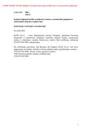
1BOILER INSTALLATION.1.1 INSTALLATIONRECOMMENDATIONS.The Eolo Star <strong>24</strong> 3 boiler has been designed forwall mounted installation or installation insidethe wall using the recessed frame provided; theymust be used to heat environments, to producehot water and similar purposes. In the case ofwall installation the wall surface must be smooth,without any protrusions or recesses enablingaccess to the rear part. They are NOT designedto be installed on plinths or floors (Fig. 1-1).By varying the type of installation the classificationof the boiler also varies, precisely:- Indoor installation:- without the 2 intake caps and with uppercasing. exhaust terminal Ø80 (configurationtype B 22);- without upper casing and with concentricterminals and separators (configuration typeC).- Outdoor installation in partially protectedareas:- without the 2 intake caps and with uppercasing. Exhaust terminal Ø80 (configurationtype C);- the upper casing is recommended but notobligatory with concentric terminals andseparators (this configuration is also type C).- Outdoor installation with recess frame:- using the spacers under the side plugs of thesealed chamber (configuration type C);- leave the plugs of the sealed chambermounted and use the concentric pipes orother types of pipes suitable for the sealedchamber for air intake and fume exhaustion(configuration type C).Only professionally qualified heating/plumbingtechnicians are authorised to install Immergasgas appliances. Installation must be carried outaccording to the standards, current legislationand in compliance with local technical regulationsand the required technical procedures.Installation of the Eolo star <strong>24</strong> 3 E boiler whenpowered by LPG must comply with the rulesregarding gases with a greater density than air(remember, as an example, that it is prohibited toinstall plants powered with the above-mentionedgas in rooms where the floor is at a lower quotathat the average external country one). Beforeinstalling the appliance, ensure that it is deliveredin perfect condition; if in doubt, contact thesupplier immediately. Packing materials (staples,nails, plastic bags, polystyrene foam, etc.) constitutea hazard and must be kept out of the reachof children. If the appliance is installed insideor between cabinets, ensure sufficient space fornormal servicing; therefore it is advisable to leaveclearance of at least 3 cm between the boilercasing and the vertical sides of the cabinet. Leaveadequate space above the boiler for possible waterand fume removal connections.Keep all flammable objects away from the appliance(paper, rags, plastic, polystyrene, etc.).Do not place household appliances underneaththe boiler as they could be damaged if the safetyvalve intervenes (if not conveyed away bya discharge funnel), or if there are leaks fromthe hydraulic connections; on the contrary, themanufacturer cannot be held responsible forany damage caused to the household appliances.In the event of malfunctions, faults or incorrectoperation, turn the appliance off immediately andcontact a qualified technician (e.g. the ImmergasTechnical After-Sales Centre, which has specificallytrained staff and original spare parts) Do notattempt to modify or repair the appliance alone.Failure to comply with the above implies personalresponsibility and invalidates the warranty.• Installation regulations: this boiler can be installedoutdoors in a partially protected area.A partially protected area is one in which theappliance is not exposed to the direct action ofthe weather (rain, snow, hail, etc...). If necessaryit is possible to install the boiler in positionstotally exposed to the direct action of the weatherusing only the cover kit (Optional) Theboiler can be installed inside a wall using theappropriate recessed frame (Optional).Important: Wall mounting of the boiler on thewall or inside the wall must guarantee stableand efficient support for the generator. Therecessed frame kit (Optional) guarantees anadequate support only if installed correctly (inaccordance with the code of practice) followingthe instructions on the instruction leaflet. Therecessed frame for the Eolo Star <strong>24</strong> 3 E boiler isnot a supporting structure and must not replacethe wall removed. It is necessary to position theboiler inside the wall. For safety reasons againstany leaks it is necessary to plaster the boilerhousing in the brick wall.The plugs (standard supply) are to be used only inconjunction with the mounting brackets or fixingtemplate to fix the appliance to the wall; they onlyensure adequate support if inserted correctly(according to technical standards) in walls madeof solid or semi-hollow brick or block. In thecase of walls made from hollow brick or block,partitions with limited static properties, or in anycase walls other than those indicated, a static testmust be carried out to ensure adequate support.N.B.: the hex head screws supplied in the blisterpack are to be used exclusively to fix the relativemounting bracket to the wall.These boilers are used to heat water to belowboiling temperature in atmospheric pressure.They must be attached to a heating system suitablefor their capacity and voltage.YESNO1-1INSTALLATORUSERTECHNICIAN3 - IE
gas supply (methane or LPG) pressure must alsobe checked according to the type used in theboiler, as insufficient levels can reduce generatoroutput and cause malfunctions.Ensure correct gas cock connection. The gassupply pipe must be suitably dimensioned accordingto current regulations in order to guaranteecorrect gas flow to the boiler even in conditionsof maximum generator output and to guaranteeappliance efficiency (technical specifications).The coupling system must conform to standards.Combustible gas quality. The appliance has beendesigned to operate with gas free of impurities;otherwise it is advisable to fit special filters upstreamfrom the appliance to restore the purityof the gas.Storage tanks (in case of supply from LPGdepot).- New LPG storage tanks may contain residualinert gases (nitrogen) that degrade the mixturedelivered to the appliance casing functioninganomalies.- Due to the composition of the LPG mixture,layering of the mixture components may occurduring the period of storage in the tanks. Thiscan cause a variation in the heating power ofthe mixture delivered to the appliance, withsubsequent change in its performance.Hydraulic attachment.Important: In order not to void the warrantybefore making the boiler connections, carefullyclean the heating system on the primary heatexchanger (pipes, radiators, etc.) with specialpickling or de-scaling products to remove anydeposits that could compromise correct boileroperation.In compliance with Standards in force it is mandatoryto treat the water in the heating systemchemically in order to protect the system andappliance from deposits of lime scale.Water connections must be made in a rationalway using the couplings on the boiler template.The boiler safety valves outlet must be connectedto a draining funnel. Otherwise, the manufacturerdeclines any responsibility in case of floodingif the drain valves cut in.Important: to preserve the duration of applianceefficiency features, in the presence of water whosefeatures can lead to the deposit of lime scale,installation of the “polyphosphate dispenser” kitis recommended. On the basis of the Standards inforce, it is mandatory to treat the water with over25 French degrees in the heating circuit and over15 French degrees for DHW using conditioningchemicals for powers < 100 kW or with softenersfor powers > 100 kW.Electrical connection: The “Eolo Star <strong>24</strong> 3 E”boiler has an IPX5D protection rating for theentire appliance. Electrical safety of the unit isreached when it is correctly connected to anefficient earthing system as specified by currentsafety standards.Important: Immergas S.p.A. declines anyresponsibility for damage or physical injurycaused by failure to connect the boiler to anefficient earth system or failure to comply withthe reference standards.Also ensure that the electrical installationcorresponds to maximum absorbed powerspecifications as shown on the boiler data-plate.The boilers are supplied complete with an “X”type power cable without plug. The power supplycable must be connected to a 230V ±10% /50Hz mains supply respecting L-N polarity andearth connection , This network must alsohave a multi-pole circuit breaker with class IIIover-voltage category. When replacing the powersupply cable, contact a qualified technician (e.g.the Immergas After-Sales Technical AssistanceService). The power cable must be laid as shown.In the event of mains fuse replacement on thecontrol board, use a 3.15A quick-blow fuse. Forthe main power supply to the appliance, neveruse adapters, multiple sockets or extension leads.1.6 REMOTE CONTROLS ANDROOM CHRONOTHERMOSTATS(OPTIONAL).La caldaia è predisposta per l’applicazione deicronotermostati ambiente o dei comandi remotiche sono disponibili come kit optional.All Immergas chronothermostats are connectedwith 2 wires only. Carefully read the userand assembly instructions contained in theaccessory kit.• On/Off digital chronothermostat (Fig. 1-5). Thechronothermostat allows:- setarea a două valori de temperatură ambient:set two room temperature values: one for day(comfort temperature) and one for night(lower temperature);- set up to four on/off differential weekly programs;- select the desired function mode from thevarious possible alternatives:• permanent functioning in comfort temp.• permanent functioning in reduced temp.• permanent functioning in adjustable antifreezetemp.The chronothermostat is powered by two 1.5VLR 6 type alkaline batteries;• Digital Remote Control Device with climatechronothermostat function (Fig. 1.6). In additionto the functions described in the previouspoint, the Digital Remote Control panel enablesthe user to control all the important informationregarding operation of the appliance andthe heating system with the opportunity ofeasily intervening on the previously set parameterswithout having to go to the place wherethe appliance is installed. The Digital RemoteControl panel is provided with self-diagnosis todisplay any boiler functioning anomalies. Theclimate chronothermostat incorporated intothe remote panel enables the system deliverytemperature to be adjusted to the actual needsof the room being heated, in order to obtainthe desired room temperature with extremeprecision and therefore with evident saving inrunning costs. The chronothermostat is feddirectly by the boiler by means of the same 2wires used for the transmission of data betweenboiler and chronothermostat.Digital Remote Control or On/Off chronothermostatelectrical connections (Optional). Theoperations described below must be performed afterhaving removed the voltage from the appliance.Any thermostat or On/Off environment chronothermostatmust be connected to clamps 40and 41 eliminating jumper X40 (Fig. 3-2). Makesure that the On/Off thermostat contact is of the“clean” type, i.e. independent of the mains supply;otherwise the electronic adjustment card wouldbe damaged. The Digital Remote Control must beconnected to clamps 40 e 41 eliminating jumperX40 on the P.C.B. (in the boiler), (Fig. 3-2).Important: If the Digital Remote Control is used,arrange two separate lines in compliance withcurrent regulations regarding electrical systems.No boiler pipes must ever be used to earth theelectric system or telephone lines. Ensure eliminationof this risk before making the boilerelectrical connections.INSTALLATORUSERTECHNICIAN1-51-65 - IE
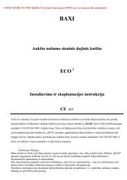
1-91-10USERINSTALLATOR1-121-13VERTICAL TERMINAL KIT FOR DIRECT DRAININGINTAKE COVER KITDiaphragmExtension in meterspipe Ø 60/100 horizontalØ 38 From 0 to 1Diaphragmexhaustintake*Extension in metreshorizontal pipe Ø 80with two bendsTECHNICIANØ 42.5 Exceeding 1- Ø 45 From 0 to 141-11DiaphragmPipe extension in metres Ø60/100 verticalØ 38 From 0 to 3.2Ø 42.5 Exceeding 3.2Ø 42.5 - From 14 to 35Diaphragmexhaustintake*Extension in metresvertical pipe Ø 80without bendsDiaphragm installation. For correct functioningof the boiler it is necessary to install a diaphragmon the outlet of the sealed chamber andbefore the intake and exhaust pipe (Fig. 1-14).The choice of suitable diaphragm takes place onthe basis of the type of pipe and its maximumextension: this calculation can be carried outusing the following tables:N.B.: the diaphragms are supplied together withthe boiler.DiaphragmPipe extension in metres Ø80/125 horizontalØ 38 From 0 to 3.3Ø 42.5 Exceeding 3.3DiaphragmPipe extension in metres Ø80/125 verticalØ 38 From 0 to 8.1Ø 42.5 Exceeding 8.1- Ø 45 From 0 to 18Ø 42.5 - From 14 to 40Diaphragmintake**Extension in metreshorizontal pipe Ø 80 withtwo bendsØ 45 From 0 to 27Diaphragmintake**Extension in metresvertical pipe Ø 80without bendsØ 45 From 0 to 27DIAPHRAGM* These maximum extension values are consideredintake with 1 metre drain pipe.** These maximum extension values are consideredexhaust with 1 metre intake pipe.1-147 - IE
1.10 INDOOR INSTALLATION.• Type C configuration, sealed chamber andforced draught.Horizontal intake - exhaust kit Ø60/100. Kitassembly (Fig. 1-15): install the bend with flange(2) on the central hole of the boiler inserting thegasket (1) and tighten using the screws in the kit.Couple the terminal pipe (3) with the male end(smooth) into the female end of the bend (withlip seals) up to the stop; making sure that the internalwall sealing plate and external wall sealingplate have been fitted, this will ensure sealingand joining of the elements making up the kit.Note: when the boiler is installed in areas wherevery rigid temperatures can be reached, a specialanti-freeze kit is available that can be installed asan alternative to the standard kit.• Coupling extension pipes and concentricelbows Ø 60/100. To snap-fit extensions withother elements of the fume extraction elements,operate as follows Install the concentric pipeor elbow with the male side (smooth) on thefemale section (with lip seal) to the end stopon the previously installed element. This willensure the sealing and joining of the elementscorrectly.The Ø 60/100 horizontal intake/exhaust kit canbe installed with the rear, right side, left side andfront outlet.• Application with rear outlet (Fig. 1-16). The970 mm pipe length enables routing througha maximum thickness of 775 mm. Normallythe terminal must be shortened. Calculatethe distance by adding the following values:Part thickness + internal projection + externalprojection. The minimum indispensableprojection values are given in the figure.• Application with side outlet (Fig. 1-17); Usingthe horizontal intake-exhaust kit, without thespecial extensions, enables routing througha wall thickness of 720 mm with the left sideoutlet and 650 with the right side outlet.• Extensions for horizontal kit. The horizontalintake-exhaust kit Ø 60/100 can be extendedup to a max. horizontal distance of 3,000 mmincluding the terminal with grid and excludingthe concentric bend leaving the boiler. Thisconfiguration corresponds to a resistance factorof 100. In these cases the special extensionsmust be requested.Connection with N°1 extension (Fig. 1-18).Max. distance between vertical boiler axis andexternal wall is 1855mm.Connection with N°2 extensions (Fig. 1-19).Max. distance between vertical boiler axis andexternal wall is 2805mm.Horizontal intake-exhaust kit Ø 80/125 Kitassembly (Fig. 1-20): install the bend with flange(2) onto the central hole of the boiler insertingthe gasket (1) and tighten using the screws in thekit. Fit the male end (smooth) of the adapter (3)up to the stop on the female end of the bend (2)(with lip seal). Fit the Ø 80/125 (4) concentricterminal pipe with the male end (smooth) to thefemale end of the adapter (3) (with lip gasket) upto the stop; making sure that the internal wallsealing plate and external wall sealing plate havebeen fitted, this will ensure sealing and joiningof the elements making up the kit.• Coupling extension pipes and concentricelbows Ø 80/125. To snap-fit extensions withother elements of the fume extraction elements,operate as follows Install the concentric pipeor elbow with the male side (smooth) on thefemale section (with lip seal) to the end stopon the previously installed element. This willensure sealing and joining of the elementscorrectly.Important: if the exhaust terminal and/or extensionconcentric pipe needs shortening, considerthat the internal duct must always protrude by 5mm with respect to the external duct.Normally the Ø 80/125 horizontal intake-exhaustkit is used if particularly long extensions are required;the Ø 80/125 kit can be installed with therear, right side, left side or front outlet.• Extensions for horizontal kit. The Ø 80/125horizontal intake-exhaust kit can be extendedup to a max. horizontal distance of 7,300 mmincluding the terminal with grid and excludingthe concentric bend leaving the boiler and theadapter Ø 60/100 in Ø 80/125 (Fig. 1-21). Thisconfiguration corresponds to a resistance factorof 100. In these cases the special extensionsmust be requested.N.B.: when installing the pipes, a section clampwith pin must be installed every 3 metres.• External grill. N.B.: for safety purposes, do noteven temporarily obstruct the boiler intakeexhaustterminal.INSTALLATORUSERTECHNICIAN12345C12C121-15The kit includes:N°1 - Gasket (1)N°1 - Concentric bend 90° (2)N°1 - Intake-exhaust concentric pipeØ60/100 (3)N°1 - Internal white wall sealing plate (4)N°1 - External grey wall sealing plate (5)C121-16C121-18C121-171-199 - IE
• Coupling of extension pipes and elbows. Toinstall snap-fit extensions with other elementsof the fume extraction elements assembly, proceedas follows: Install the pipe or elbow withthe male side (smooth) on the female section(with lip seal) to the end stop on the previouslyinstalled element. This will ensure sealing andjoining of the elements correctly.• Figure 1-27 shows the configuration withvertical exhaust and horizontal intake.• Installation clearances. Figure 1-26 gives themin. installation space dimensions of the Ø80/80 separator terminal kit in limited conditions.• Extensions for the separator kit Ø 80/80. Themax. vertical straight length (without bends)that can be used for Ø 80 intake and exhaustpipes is 41 metres of which 40 intake and 1exhaust. The total length corresponds to aresistance factor of 100. The total usable lengthobtained by adding the length of the intake andexhaust pipes Ø 80 must not exceed the valuesstated in the following table. If mixed accessoriesor components are used (e.g. changing froma separator Ø 80/80 to a concentric pipe), themaximum extension can be calculated by usinga resistance factor for each component or theequivalent length. The sum of these resistancefactors must not exceed 100.• Temperature loss in fume ducts. To preventproblems of fume condensate in the exhaustpipe Ø 80, due to fume cooling through thewall, the length of the pipe must be limited tojust 5 m. Fig. 1-28). If longer distances mustbe covered, use Ø 80 pipes with insulation (seeinsulated separator kit Ø 80/80 chapter).N.B.: when installing the Ø 80 ducts, a sectionclamp with pin must be installed every 3 metres.* The air intake pipe can be increased to 2.5metres if the exhaust bend is eliminated, 2metres if the air intake bend is eliminated, and4.5 metres eliminating both bends.INSTALLATOR71-251-279S415567A32C528C82The kit includes:N°1 - Exhaust gasket (1)N°1 - Female intake flange (3)N°1 - Flange gasket (2)N°1 - Female exhaust flange (4)N°2 - 90° bend Ø 80 (5)N°1 - Intake terminal Ø 80 (6)N°2 - Internal white wall sealing plates (7)N°1 - External grey wall sealing ring (8)N°1 - Exhaust pipe Ø 80 (9)1-26C42C82USERTECHNICIAN1-28Maximum usable length(including intake terminal with grill and two 90° bends)NON INSULATED PIPEINSULATED PIPEExhaust (m) Intake (m) Exhaust (m) Intake (m)1 36,0* 6 29,5*2 34,5* 7 28,0*3 33,0* 8 26,5*4 32,0* 9 25,5*5 30,5* 10 <strong>24</strong>,0** The air intake pipe can be increased to 2.5 metres if the exhaust bend is11 22,5*eliminated, 2 metres if the air intake bend is eliminated, and 4.5 metreseliminating both bends.12 21,5*Important: the boiler was designed to evacuatecombustion product up to a maximum extensionof 27 linear m to the exhaust, with 1 m plus 90°bend at intake. If installation requires an extensionof the flue fittings up to the exhaust thatexceeds the 12 m recommended, it is necessaryto properly consider the possibility that condensationmay form inside the duct and thereforeImmergas “Serie Blu” insulated flue fittings, orother flue fittings with similar characteristics,should be used.11 - IE
INSTALLATORUSERTECHNICIANInsulated separator kit Ø 80/80. Kit assembly(Fig. 1-29): install flange (4) on the central holeof the boiler, fitting gasket (1) and tighten withthe flat-tipped hex screws included in the kit.Remove the flat flange present in the lateral holewith respect to the central one (according to needs)and replace it with the flange (3), positioningthe gasket (2) already present in the boiler andtighten using the supplied self-threading screws.Insert and slide cap (6) onto bend (5) from themale side (smooth), and join bends (5) with themale side (smooth) in the female side of flange(3). Fit bend (11) with the male side (smooth)into the female side of flange (4). Fit the maleend (smooth) of the intake terminal (7) up to thestop on the female end of the bend (5), makingsure you have already inserted the wall sealingplates (8 and 9) that ensure correct installationbetween pipe and wall, then fix the closing cap(6) on the terminal (7). Join the exhaust pipe (10)with the male side (smooth) in the female sideof the bend (11) to the end stop, ensuring thatthe wall sealing plate (8) is already inserted forcorrect installation between the pipe and flue.• Coupling extension pipes and elbows.To snap-fit extensions with other elements ofthe fume extraction elements, operate as follows:Install the concentric pipe or elbow withthe male side (smooth) on the female section(with lip seal) to the end stop on the previouslyinstalled element. This will ensure sealing andjoining of the elements correctly.• Insulation of separator terminal kit. In case ofproblems of fume condensate in the exhaust pipesor on the outside of intake pipes, Immergassupplies insulated intake and exhaust pipes onrequest. Insulation may be necessary on theexhaust pipe due to excessive temperature lossof fumes during conveyance. Insulation may benecessary on the intake pipe as the air entering(if very cold) may cause the outside of the pipeto fall below the dew point of the environmentalair. The figures (Fig. 1-29 and 1-30) illustratedifferent applications of insulated pipes.Insulated pipes are formed of a Ø 80 internalconcentric pipe and a Ø 125 external pipe withstatic air space. It is not technically possibleto start with both Ø 80 elbows insulated, asclearances will not allow it. However startingwith an insulated elbow is possible by choosingeither the intake or exhaust pipe. When startingwith an insulated intake bend, it must beinserted onto its flange up to the stop on thefume exhaust flange, which will ensure that thetwo intake and exhaust outlets are at the sameheight.• Temperature loss in insulated fume ducting.To prevent problems of fume condensate inthe exhaust pipe Ø 80, due to fume coolingthrough the wall, the length of the pipe mustbe limited to 12 m. The figure (Fig. 1-31) illustratesa typical insulation application in whichthe intake pipe is short and the exhaust pipe isvery long (over 5 m). The entire intake pipe isinsulated to prevent moist air in the place wherethe boiler is installed, in contact with the pipecooled by air entering from the outside. Theentire exhaust pipe, except the elbow leavingthe splitter is insulated to reduce heat loss fromthe pipe, thus preventing the formation of fumecondensate.N.B.: When installing the ducts, a sectionclamp with pin must be installed every 2 metres.• Configuration type B, open chamber andforced draught.When using type B installation configurationindoors, it is compulsory to install the relative uppercover kit along with the fumes discharge kit.The air intake comes directly from the area wherethe boiler is installed and from the flue exhaustin each single flue or directly from outdoors.The boiler in this configuration, following theassembly instructions on pages 8 and 9, is classifiedas type B.With this configuration:- air intake takes place directly from the environmentin which the boiler is installed and onlyfunctions in permanently ventilated rooms;- the flue exhaust must be connected to its ownindividual flue or channelled directly into theexternal atmosphere.- Type B open chamber boilers must not beinstalled in places where commercial, artisanor industrial activities take place, which useproducts that may develop volatile vapoursor substances (e.g. acid vapours, glues, paints,solvents, combustibles, etc.), as well as dusts(e.g. dust deriving from the working of wood,coal fines, cement, etc.), which may be damagingfor the components of the appliance andjeopardise functioning.When using type B installation configurationindoors, it is compulsory to install the relative uppercover kit along with the fumes discharge kit.The technical regulations in force must berespected.810115 6789C82C82S3A421The kit includes:N°1 - Exhaust gasket (1)N°1 - Flange seal (2)N°1 - Female intake flange (3)N°1 - Female exhaust flange (4)N°1 - Bend 90° Ø 80 (5)N°1 - Pipe closure cap (6)N°1 - Intake terminal Ø 80 insulated (7)N°2 - Internal white wall sealing plates (8)N°1 - External grey wall sealing plate (9)N°1 - Discharge pipe Ø 80 insulated (10)N°1 - Concentric bend 90° Ø 80/125 (11)1-291-30C821-3112 - IE
1.11 FUME EXHAUST TO FLUE/CHIMNEY.Flue exhaust does not necessarily have to be connectedto a branched type traditional flue. Flueexhaust can be connected to a special LAS typemultiple flue. Multiple and combined flues mustbe specially designed according to the calculationmethod and requirements of the standards, byprofessionally qualified technical personnel.Chimney or flue sections for connection of theexhaust pipe must comply with requisites oftechnical standards in force.1.12 DUCTING OF EXISTING FLUES.With a specific “ducting system” it is possibleto reuse existing flues, chimneys and technicalopenings to discharge the boiler fumes. Ductingrequires the use of ducts declared to be suitablefor the purpose by the manufacturer. Follow theinstallation and user instructions provided by themanufacturer and the requirements of standards.1.13 FLUES, CHIMNEYS AND CHIMNEYCAPS.The flues, chimneys and chimney caps for theevacuation of combustion products must be incompliance with applicable standards.Positioning the draft terminals. Draft terminalsmust:- be installed on external perimeter walls of thebuilding;- be positioned according to the minimum distancesspecified in current technical standards.Fume exhaust of forced draught appliances inclosed open-top environments. In spaces closedon all sides with open tops (ventilation pits,courtyards etc.), direct fume exhaust is allowedfor natural or forced draught gas appliances witha heating power range from 4 to 35 kW, providedthe conditions as per the current technicalstandards are respected.1.14 SYSTEM FILLING.Once the boiler is connected, proceed withsystem filling via the filling valve (Fig. 2-2).Filling is performed at low speed to ensurerelease of air bubbles in the watervia the boiler and heating system vents.The boiler has a built-in automatic ventingvalve on the circulator. Open the radiatorair vent valves. Close radiator ventvalves only when water escapes from them.Close the filling valve when the boiler manometerindicates approx. 1.2 bar.N.B.: during these operations turn on the circulationpump at intervals, by means of the stand-by/summer winter switch positioned on the controlpanel. Vent the circulation pump by loosening thefront cap and keeping the motor running.Tighten the cap afterwards.1.15 GAS SYSTEM <strong>STAR</strong>T-UP.To start up the system proceed as follows:- open windows and doors;- avoid presence of sparks or naked flames;- bleed all air from pipelines;- check that the internal system is properly sealedaccording to specifications.1.16 BOILER <strong>STAR</strong>T UP (IGNITION).For issue of the Declaration of Conformity providedfor by Italian Law, the following must beperformed for boiler start-up:- check that the internal system is properly sealedaccording to specifications;- ensure that the type of gas used corresponds toboiler settings;- switch the boiler on and ensure correct ignition;- make sure that the gas flow rate and relevantpressure values comply with those given in themanual (parag. 3.17);- ensure that the safety device is engaged in theevent of gas supply failure and check activationtime;- check activation of the main switch locatedupstream from the boiler;- check that the concentric intake-exhaust terminal(if fitted) is not blocked.The boiler must not be started up in the event offailure to comply with any of the above.N.B.: the initial check of the boiler must be performedby a qualified technician. The conventionalwarranty of the boiler comes into effect from thedate of the check itself. The initial check certificateand warranty are issued to the user.1.17 CIRCULATION PUMP.Eolo Star <strong>24</strong> 3 E Range boilers are supplied with abuilt-in circulation pump with 3-position electricspeed control. The boiler does not operate correctlywith the circulation pump on first speed.To ensure optimal boiler operation, in the caseof new systems (single pipe and module) it isrecommended to use the circulation pump atmaximum speed. The circulation pump is alreadyfitted with a capacitor.Pump release. If, after a prolonged period ofinactivity, the circulation pump is blocked,unscrew the front cap and turn the motor shaftusing a screwdriver. Take great care during thisoperation to avoid damage to the motor.By-pass regulation (part. <strong>24</strong> Fig. 1-33). If necessary,the by-pass can be regulated according toplant requirements from a minimum (by-passexcluded) to a maximum (by-pass inserted)represented by the following graphics (Fig. 1-32).Make the regulation using a flat head screwdriver,turn clockwise and insert the by-pass, anticlockwiseit is excluded.INSTALLATORUSERTECHNICIANTotal head available to the plant.Head (kPa)DBCAHead (m H 2O)A = Head available to the systemat maximum speed with bypassexcluded.B = Head available to the systemat maximum speed with bypassinserted.C = Head available to the systemat second speed with by-passexcluded.D = Head available to the systemat second speed with by-passinserted.Flow rate (l/h)1-3213 - IE
INSTALLATORUSERTECHNICIANIgnition of the boiler (Fig. 2-1). Before ignition,make sure the heating system is filled with waterand that the manometer (7) indicates a pressureof 1 ÷ 1.2 bar.- Open the gas cock upstream from the boiler.- Press key (2) and select the summer positionor winter ( ) position of the boiler ( ).When in summer position( ) the domestichot water temperature is regulated by keys (3-4).When in winter position ( ) the system watertemperature is regulated by keys (5-6) whilst theregulation of the domestic hot water temperatureis regulated using keys (3-4), pressing (+) toincrease and (-) to reduce.From this moment the boiler functions automatically.With no demand for heat (heating ordomestic hot water production) the boiler goesto “standby” function, equivalent to the boilerbeing powered without presence of flame. Eachtime the boiler ignites, the relative flame presentsymbol is displayed (15).2.4 FAULT AND ANOMALY SIGNALS.The boiler signals out anomalies by flashing onthe display and relative error codes, listed on thetable, are displayed.codeAnomaly signalled displayed(flashing)Ignition block 01Safety thermostat block (overtemperature),flame control 02anomalyElectro-mechanical contacts 04Delivery probe anomaly 05Domestic hot water probeanomaly06Insufficient system pressure 10Fumes pressure switch failure 11Parasite flame 20Insufficient circulation 27Extruder presence 28Communication loss withCRD31Ignition block. The boiler ignites automaticallywith each demand for room heating or hotwater production. If this does not occur within10 seconds, the boiler goes into ignition block(code 01). To eliminate “ignition block” the Resetbutton (1) must be pressed. On commissioningor after extended inactivity it may be necessaryto eliminate the “ignition block”. If this phenomenonoccurs frequently, contact a qualifiedtechnician for assistance (e.g. Immergas After-Sales Technical Assistance Service).Over temperature thermostat block. Duringnormal functioning, if a fault causes excessiveoverheating internally, the boiler goes into overtemperature block (code 02). After allowing tocool, eliminate the “overtemperature block” bypressing the Reset key (1). If this phenomenonoccurs frequently, contact a qualified technicianfor assistance (e.g. Immergas After-Sales TechnicalAssistance Service).Electro-mechanical contacts This occurs whenthe safety thermostat, the fume pressure switch orthe system pressure switch do not work properly(code 04). Try resetting the boiler. If the anomalycontinues contact a qualified technician forassistance (e.g. Immergas After-Sales TechnicalAssistance Service).Delivery probe anomaly If the board detects ananomaly on the delivery probe (code 05), the boilerwill not start; contact a qualified technician forassistance (e.g. Immergas After-Sales TechnicalAssistance Service).Domestic hot water probe anomaly. If the boarddetects an anomaly on the delivery probe (code06), the boiler will not start; contact a qualifiedtechnician for assistance (e.g. Immergas After-Sales Technical Assistance Service).Insufficient system pressure. Water pressureinside the heating system (code 10), sufficient toguarantee the correct functioning of the boiler,is not detected. Check that the system pressureis between 1÷1.2 bar.Fumes pressure switch failure. This occurs if theintake or exhaust pipes are blocked or in case ofa fan fault (code 11). If normal conditions arerestored the boiler restarts without having to bereset. If this anomaly persists, contact a qualifiedtechnician for assistance (e.g. Immergas After-Sales Technical Assistance Service.)Parasite flame. This occurs in case of a leak onthe detection circuit or anomaly in the flamecontrol unit. (code 20), try to reset the boiler.If the anomaly continues contact a qualifiedtechnician (e.g. Immergas After-Sales TechnicalAssistance Service).Insufficient water circulation. This occurs ifthere is overheating in the boiler due to insufficientwater circulating in the primary circuit(code 27); the causes can be:- low circulation; check that no shut off devicesare closed on the heating circuit and that thesystem is free of air (deaerated);- circulating pump blocked; free the circulatingpump.If this phenomenon occurs frequently, contact aqualified technician for assistance (e.g. ImmergasAfter-Sales Technical Service).Domestic hot water extruder circuit. If duringthe heating phase, a rise in domestic hot watertemperature occurs, an anomaly is signalled (code28) and heating temperature is reduced to limitthe formation of lime scale in the heat exchanger.Check that all domestic hot water system cocksare closed and are not drawing and check alsothat there are no leaks in the system. Once goodconditions are restored in the domestic hot watersystem, the boiler returns to normal functioning.If this anomaly persists, contact a qualified technicianfor assistance (e.g. Immergas After-SalesTechnical Assistance Service).Loss of Digital Remote Control communication.This occurs 1 minute after communicationloss between the boiler and the CRD (code 31).To reset the error code, remove and re-applypower to the boiler. If this phenomenon occursfrequently, contact a qualified technician forassistance (e.g. Immergas After-Sales TechnicalAssistance Service).Boiler shutdown Press key (2 Fig. 2-1) () until the following symbol appears( ).N.B.: in these conditions the boiler is consideredstill powered.Disconnect the external omnipolar boiler switchand close the gas cock upstream of the appliance.Never leave the boiler switched on if left unusedfor prolonged periods.2.5 RESTORE HEATING SYSTEMPRESSURE.Periodically check the system water pressure.The boiler pressure gauge should read a pressurebetween 1 and 1.2 bar.If the pressure is below 1 bar (with the circuit cool)restore normal pressure via the cock located in thelower part of the boiler (Fig. 2-2).N.B.: close the cock after the operation.If pressure values reach around 3 barthe safety valve may be activated.In this case contact a professional technicianfor assistance.In the event of frequent pressure drops, contactqualified staff for assistance to eliminate thepossible system leakage.2.6 DRAINING THE SYSTEM.To drain the boiler, use the special drain cock(Fig. 1-33).Before draining, ensure that the filling cock isclosed.2.7 ANTI-FREEZE PROTECTION.The boiler is supplied with an antifreeze functionas per standard that activates the function of thepump and the burner when the internal systemwater temperature in the boiler falls below 4 °C(protection range to a minimum temperatureof -5°C) and stops when it exceeds 42°C. Theantifreeze function is guaranteed if the boileris fully operative, is not in “block” status and iselectrically powered. To avoid keeping the systemswitched on in case of a prolonged absence, thesystem must be drained completely or antifreezesubstances must be added to the heating systemwater. In both cases the boiler domestic hot watercircuit must be drained. In systems that are drainedfrequently, filling must be carried out withsuitably treated water to eliminate hardness thatcan cause lime-scale.All information relative to the anti-freeze protectionis stated in Par. 1.4. In order to guarantee theintegrity of the appliance and the domestic hotwater heating system in zones where the temperaturefalls below zero, we recommend the heatingsystem is protected using anti-freeze liquid andinstallation of the Immergas Anti-freeze Kit inthe boiler (Par. 1.4). In the case of prolongedinactivity (second case), we also recommend that:- disconnect the electric power supply;- drain completely the boiler domestic hot watercircuit using the exhaust valves provided (Fig.1-33) and the internal domestic hot watersystem.16 - IE
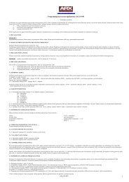
2.8 CASE CLEANING.Use damp cloths and neutral detergent to cleanthe boiler casing. Never use abrasive or powderdetergents.2.9 DECOMISSIONING.In the event of permanent shutdown of the boiler,contact professional staff for the procedures andensure that the electrical, water and gas supplylines are shut off and disconnected.TECHNICIANINSTALLATORUSERBottom view.Key:1 - Filling valve2 - Draining valve2-217 - IE
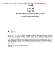
INSTALLATOR3BOILER <strong>STAR</strong>T-UP.(INITIAL CHECK)To commission the boiler:- ensure that the declaration of conformity ofinstallation is supplied with the appliance;- ensure that the type of gas used corresponds toboiler settings;- check connection to a 230V-50Hz powermains, correct L-N polarity and the earthingconnection;- make sure the heating system is filled with waterand that the manometer indicates a pressureof 1÷1.2 bar;- make sure the air valve cap is open and that thesystem is well deaerated;- switch the boiler on and ensure correct ignition;- make sure the gas maximum, medium andminimum flow rate and pressure valuescorrespond to those given in the handbook(Paragraph 3.17);- check activation of the safety device in the eventof no gas, as well as the relative activation time;- check activation of the main switch locatedupstream from the boiler;- check that the intake and/or exhaust terminalsare not blocked;- check activation of the “no air” safety pressureswitch;- ensure activation of all adjustment devices;- seal the gas flow rate regulation devices (ifsettings are modified);- ensure production of domestic hot water;- ensure sealing efficiency of water circuits;- check ventilation and/or aeration of the installationroom where provided.If any checks/inspection relative to safety givenegative results, do not start the system.USER3.1 HYDRAULIC LAYOUT.TECHNICIANKey:1 - Domestic hot water probe2 - Domestic hot water flow switch3 - Gas valve4 - Flow limiter5 - System draining valve6 - Burner7 - Rapid heat exchanger8 - Fan9 - Sealed chamber10 - Fumes pressure switch11 - Fumes hood12 - System expansion vessel13 - Delivery probe14 - Safety thermostat15 - Air vent valve16 - Boiler circulating pump17 - System pressure switch;18 - By-pass19 - 3 bar safety valve20 - System filling valveG - Gas supplyAC - Domestic hot water outletAF - Domestic hot water inletR - System returnM - System delivery3-118 - IE
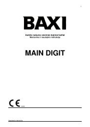
3.2 WIRING DIAGRAM.45675665568 8 101088101011119999INSTALLATORKey:B1 - Delivery probeB2 - Domestic hot water probeDRC - Digital Remote Control (optional)DS1 - DisplayE3 - Ignition and detection electrodesE4 - Safety thermostatF1 - Phase fuseF2 - Neutral fuse32M1 - Boiler circulating pumpM20 - FanS2 - Selector switch functioningS3 - Reset block keysS4 - Domestic hot water flow switchS5 - System pressure switch;S6 - Fumes pressure switchS20 - Room thermostat (optional)S21 - Domestic hot water temperature1increase keyS22 - Domestic hot water temperaturedecrease keyS23 - Heating temperature increase keyS<strong>24</strong> - Heating temperature decrease keyT1 - Switch-on transformerT2 - Boiler board transformerU1 - Rectifier inside the gas valveconnector (Only available onHoneywell gas valves)X40 - Room thermostat jumperY1 - Gas valveY2 - Gas valve modulator1 - User interface2 - N.B.: The user interface is on thewelding side of the boiler board3 - The X6 connector is used forautomatic inspection4 - 230 Vac 50Hz power supply5 - Blue6 - Brown7 - Yellow/Green8 - Black9 - Grey10 - White11 - Red3-2USERTECHNICIANThe boiler is designed for application of a roomthermostat (S20), an On/Off room chronothermostat,a program timer or a Digital RemoteControl (DRC). Connect it to clamps 40 –41eliminating jumper X40.3.3 TROUBLESHOOTING.N.B.: maintenance interventions must be carriedout by a qualified technician (e.g. ImmergasAfter-Sales Technical Assistance Service).- Smell of gas. Caused by leakage from gas circuitpipelines. Check sealing efficiency of gas intakecircuit.- The fan works but ignition discharge does notoccur on the burner ramp. The fan may startbut the safety air pressure switch does notswitch the contact over. Make sure:1) the intake-exhaust duct is not too long (overallowed length).2) the intake-exhaust pipe is not partially blocked(on the exhaust or intake side).3) the diaphragm of the fume exhaust is adequatefor the length of the intake-exhaust duct.4) that the sealed chamber is kept in good conditions.5) the fan power supply voltage is not less than 196V.- Irregular combustion (red or yellow flame).This may be caused by: dirty burner, incorrectcombustion parameters, intake - exhaust terminalnot correctly installed. Clean the abovecomponents and ensure correct installation ofthe terminal.- Frequent activation of the temperature overloadthermostat. This may be caused by lackof water in the boiler, insufficient water circulationin the circuit, a blocked circulator or ananomaly of the boiler adjustment board. Checkon the manometer that the system pressure iswithin established limits. Check that radiatorvalves are not all closed.- Presence of air in the system. Check opening ofthe special air bleeding cap (Fig. 1-33). Makesure the system pressure and expansion vesselpre-charge values are within the set limits; thepre-charge value for the expansion vessel mustbe 1.0 bar, and system pressure between 1 and1.2 bar.- Ignition block paragraph 2.4 and 1.5 (electricconnections).- Low water flow: if, as a result of lime scale (calciumand magnesium), the domestic hot watersystem does not work properly contact a qualifiedtechnician for descaling e.g. ImmergasAfter-Sales Technical Service. Descaling mustbe carried out on the domestic hot water sideof the bithermal heat exchanger in accordancewith good practice. To preserve integrity andefficiency of the heat exchanger, a non corrosivedescaler must be used. Cleaning must becarried out without the use of tools which candamage the heat exchanger.3.4 CONVERTING THE BOILER TOOTHER TYPES OF GAS.If the boiler has to be converted to a different gastype to that specified on the data plate, requestthe relative conversion kit for quick and easyconversion.Boiler conversion must be carried out by aqualified technician (e.g. Immergas After-SalesTechnical Assistance Service).To convert to another type of gas the followingoperations are required:- remove the voltage from the appliance;- replace the main burner injectors, making sureto insert the special seal rings supplied in thekit, between the gas manifold and the injectors.- apply voltage to the appliance;- select, using the boiler key, the gas parametertype (P1) and select (nG) in the case of methanesupply or (LG) in the case of LPG supply;- adjust the boiler nominal heat output;- adjust the boiler nominal heat output in domestichot water phase;- adjust the boiler nominal heat output in heatingphase;- adjust (eventually) the maximum heatingpower;- seal the gas flow rate devices (if adjusted);- after completing conversion, apply the sticker,present in the conversion kit, near the dataplate.Using an indelible marker pen, cancelthe data relative to the old type of gas.These adjustments must be made with referenceto the type of gas used, following that given inthe table (Parag. 3.17).19 - IE
SIT 845 GAS valveVK 4105 M GAS valveINSTALLATORKey:1 - Coil2 - Minimum power adjustment nut3 - Maximum power adjustment nut4 - Gas valve outlet pressure point5 - Gas valve inlet pressure point6 - Protection hood3-3USERTECHNICIAN3.5 CHECKS FOLLOWINGCONVERSION TO ANOTHER TYPEOF GAS.After making sure that conversion was carriedout with a nozzle of suitable diameter for thetype of gas used and the settings are made at thecorrect pressure, check that:- there is no flame in the combustion chamber;- the burner flame is not too high or low and thatit is stable (does not detach from burner);- the pressure testers used for calibration areperfectly closed and there are no leaks fromthe gas circuit.N.B.: all boiler adjustment operations mustbe carried out by a qualified technician (e.g.Immergas After-Sales Technical Assistance).Burner adjustment must be carried out usinga differential “U” or digital type pressure gaugelocated above the sealed chamber (part. 9 Fig.1-33) and the gas valve pressure outlet (part. 4Fig. 3-3), keeping to the pressure value given inthe table (Par. 3.17) according to the type of gasfor which the boiler is prepared.3.6 POSSIBLE ADJUSTMENTS.• Adjustment of boiler nominal thermal heatoutput.- Press the (+) key to adjust the domestic hotwater temperature (3 Fig. 2-1) up to the maximumtemperature function.- Open the domestic hot water cock in order toprevent modulation intervention.- Adjust the boiler nominal power on the brassnut (3 Fig. 3.3), keeping to the maximumpressure values stated in the tables (Par. 3.17)depending on the type of gas.- By turning in a clockwise direction the heatingpotential increases and in an anti-clockwisedirection it decreases.• Adjust the boiler minimum heat input in thedomestic hot water phase (Fig. 3-3).N.B.: only proceed after having calibrated thenominal pressure.To adjust the minimum thermal output in domestichot water phase, turn the nut (2) locatedon the gas valve blocking the brass nut (3);- disconnect the power supply to the modulatingcoil (just disconnect a fasten); By turning thescrew in a clockwise direction, the pressureincreases, in an anti-clockwise direction it decreases.On completion of calibration, re-applythe power supply to the modulating coil. Thepressure, to which the boiler minimum powermust be adjusted, must not be lower than thatstated in the tables (Par. 3.17) depending onthe type of gas.N.B.: to adjust the gas valve, remove the plasticcap (6); after adjusting, refit the cap.• Adjustment of the boiler minimum heat outputin heating phase.N.B.: only proceed after having calibrated theminimum domestic hot water pressure.To adjust the minimum heat output during theheating phase, change parameter (5), increasingthe value the pressure increases, reducing it thepressure drops.- The pressure to which the boiler minimum heatoutput must be adjusted must not be lower thanthat stated in the tables (Parag. 3.17).3.7 PROGRAMMING THE P.C.BThe Eolo Star <strong>24</strong> 3 E boiler is prepared for possibleprogramming of several functioning parameters. Bymodifying these parameters as described below, theboiler can be adapted according to specific needs.To access the programming phase, proceed asfollows:- press keys (1) and (2) at the same time forapproximately 15 seconds;- Using keys (3) and (4), select the parameter tobe changed indicated in the following table:List ofparametersP0P1P2P3P4P5P6P7P8DescriptionSelect solar panelsSelect gas typeselect special gas type G110Activate anti extruder functionActivate domestic hot waterpost circulationMinimum heating powerMaximum heating powerHeating ignition timerHeating ramp timer- adjust the corresponding value consulting thetable using keys (5) and (6);- confirm the set value pressing the reset key(1) for approximately 5 seconds; pressing keys(3) + and (4) - at the same time to adjust thedomestic hot water temperature, the operationis cancelled.N.B.: after a period of time, without touchingany keys, the operation cancels automatically.Select solar panels By selecting this function, theboiler is set to be used with solar panels. Settingparameter P0 at on “solar”, the switching off ofthe burner is connected to the adjustment of thedomestic hot water temperature. In OFF mode,the burner is switched off at maximum value.N.B.: together with a solar valve kit, set theparameter P0 at on “solar” mode (correlated).Select solar panelsRange of values which canbe seton "solar" - oF (Standardsettings)ParameterP0Select gas type The setting of this function is usedto adjust the boiler in order to function with LPGgas or Methane gas.Select gas typeRange of values which canbe setLG (GPL) o nG (Metano)(Standard settings)ParameterP1Town Gas G110 – Industrial gas. The settingof this function is used to adjust the boiler inorder to function with gases from the first family.Town Gas G110 - Industrial gas (first familygas)Range of values which canParameterbe seton - oF (Standard setting)P220 - IE
Anti-Extruder function. This function reducesthe heating temperature to 57°C in the case thatdomestic hot water circulation is detected in theheating mode.Activate anti-extruder functionRange of values which canbe seton (Standard setting) - oFParameterP3Domestic hot water post circulation functionWith the post circulation function active afterdomestic hot water flow, the pump remains onfor 2.5 seconds in winter time and 1.5 secondsin summer time to reduce the formation oflime scale.Activate domestic hot water post circulationRange of values which canParameterbe seton (Settaggio di serie) - oFP4Heating power. The Eolo Star <strong>24</strong> 3 E boiler is fittedwith an electronic modulation which adaptsthe power of the boiler to effective heat requestsof the home. Then the boiler works normally in avariable gas pressure field between the minimumheating power and the maximum heating powerdepending on the system’s heating load.N.B.: The Eolo Star <strong>24</strong> 3 E boiler is produced andcalibrated in the heating phase to the nominalheat output. Approximately 10 minutes are neededto reach the nominal heat output changeableusing parameter (P6).N.B.: the selection of the “Minimum heatingpower” and “Maximum heating power” parameters,in the presence of a heating request, allowsswitch-on of the boiler and power supply of themodulator with current equal to the value of therespective set value.Minimum heating powerRange of values which canbe setfrom 0 % Imax. to 63 % Imax.Maximum heating powerRange of values which canbe setfrom 0 % Imax. to 99 % Imax.(Standard setting)ParameterP5ParameterP6Timer setting. The boiler has an electronictiming device that prevents the burner fromigniting too often in the heating phase. The boileris supplied as per standard with a timer adjustedat 3 minutes.Heating ramp timing. The boiler performs anignition ramp of about 10 minutes to arrive fromminimum power to nominal heating power.Heating ramp timingRange of values which canbe setfrom 1 to 101 = 30 seconds2 = 2 minutes10 = 10 minutes (Standardsetting)ParameterP83.8 AUTOMATIC SLOW IGNITIONFUNCTION WITH TIMED RAMPDELIVERY.In the ignition phase the P.C.B. carries out anincreasing gas delivery ramp (with pressure valuesthat depend on the type of gas selected) withpreset duration. This prevents every calibrationor precision adjustment of the boiler ignitionphase in any conditions of use.3.9 “CHIMNEY SWEEP FUNCTION”.When activated, this function forces the boilerat max. output for 15 minutes.In this state all adjustments are excluded andonly the temperature safety thermostat and thelimit thermostat remain active. To activate thechimney sweep function, press the Reset key forat least 10 seconds with the boiler on stand-by. Itsactivation is indicated by the flashing symbols (8and 11 Fig. 2-1). This function allows the technicianto check the combustion parameters. Afterthe checks, deactivate the function switching theboiler off and then on again.3.10 HEATING TIMER.The Eolo Star <strong>24</strong> 3 E boiler has an electronictiming device that prevents the burner fromigniting too often in the heating phase. The boileris supplied as per standard with a timer adjustedat 3 minutes. To adjust the timer values, followinstructions for parameter settings by selectingparameter (P7) and set it with one of the valuesindicated on the relative table.3.11 PUMP ANTI-BLOCK FUNCTION.In summer function mode ( ) the boiler has afunction that starts the pump at least once every<strong>24</strong> hours for the duration of 30 seconds in orderto reduce the risk of the pump becoming blockeddue to prolonged inactivity.In winter function mode ( ) the boiler has afunction that makes the pump start at least onceevery 3 hours for 30 seconds.3.12 FUNZIONE ANTITRAFILACIRCUITO SANITARIO.This function reduces the heating temperatureto 57°C if the domestic hot water circulation isdetected in the heating mode. The function canbe excluded using parameter (P3).3.14 P.C.B. PERIODICAL SELF-CHECK.During functioning in heating mode or withboiler in standby, the function activates every 18hours after the last boiler check/power supply. Incase of functioning in domestic hot water modethe self-check starts within 10 minutes after theend of the withdrawing in progress, for durationof approx. 10 seconds.N.B.: during self-check, the boiler remains off,including signalling.INSTALLATORUSERTECHNICIANHeating ignitions timerRange of values which canbe setfrom 1 to 101 = 30 seconds2 = 2 minutes3 = 3 minutes (Standardsetting)ParameterP73.13 RADIATORS ANTI-FREEZEFUNCTION.If the system return water is below 4°C, the boilerstarts up until reaching 42°C.21 - IE
INSTALLATORUSERTECHNICIAN3.15 CASING REMOVAL(Fig 3-4).To facilitate boiler maintenance the casing canbe completely removed as follows:- Remove frame (1) grasping the edges and pullingtowards oneself as indicated by the arrow.- Loosen the 2 front screws (2) and the 2 screwfasteners (3) below on the casing (4).- Pull the casing (4) towards yourself and upat the same time to detach it from the upperhooks.3.16 YEARLY APPLIANCE CHECK ANDMAINTENANCE.The following checks and maintenance shouldbe performed at least once a year.- Clean the flue side of the heat exchanger.- Clean the main burner.- Visually check the fume hood for deteriorationor corrosion.- Check correct lighting and operation.- Ensure correct calibration of the burner indomestic water and heating phases.- Check correct operation of control andadjustment devices and in particular:- intervention of main electrical switch positionedoutside of the boiler;- system control thermostat intervention;- domestic hot water control thermostat intervention.- Check that the internal system is properlysealed according to specifications.- Check the intervention of the device against nogas ionization flame control. Intervention timemust be less than 10 seconds.- Visually check for water leaks or oxidationfrom/on connections.- Visually check that the water safety drain valveis not blocked.- Check that, after discharging system pressureand bringing it to zero (read on boiler manometer),the expansion vessel charge is at 1.0 bar.- Check that the system static pressure (withsystem cold and after refilling the system bymeans of the filling valve) is between 1 and 1.2bar.- Check visually that the safety and controldevices have not been tampered with and/orshorted, in particular:- temperature safety thermostat;- water pressure switch;- air pressure switch.- Check the condition and integrity of the electricalsystem and in particular:- electrical power cables must be inside thewhipping;- there must be no traces of blackening orburning.22 - IE
TECHNICIANUSERINSTALLATOR422313-423 - IE
INSTALLATOR3.17 VARIABLE HEAT POWER.N.B.: the pressures indicated in the table representthe difference in existing pressures betweenthe gas valve outlet and the combustion chamber.The adjustments should therefore, be carriedout using a differential manometer (small “U”-shaped column or digital manometer) with theprobes inserted in the pressure test gas valveoutlet and on the sealed chamber positive pressuretest. The power data in the table has beenobtained with intake-exhaust pipe measuring 0.5m in length. Gas flow rates refer to heating powerbelow a temperature of 15°C and at a pressure of1013 mbar. Burner pressure values refer to useof gas at 15°C.METHANE (G20) BUTANE (G30) PROPANE (G31)USERTECHNICIANHEATINGPOWERBURNERGAS FLOWRATEPRESS. BURNERNOZZLESBURNERGAS FLOWRATEPRESS. BURNERNOZZLESBURNERGAS FLOWRATEPRESS. BURNERNOZZLES(kW) (kcal/h) (m 3 /h) (mbar) (mm H 2O) (kg/h) (mbar) (mm H 2O) (kg/h) (mbar) (mm H 2O)23,8 20468 H 2,70 11,40 116,3 2,01 28,20 287,6 1,98 36,30 370,223,0 19780E2,61 10,65 108,6 1,94 26,30 268,2 1,91 33,97 346,4A21,9 18806 T 2,48 9,65 98,4 1,85 23,76 <strong>24</strong>2,3 1,82 30,84 314,521,0 18060 I 2,38 8,92 91,0 1,78 21,93 223,6 1,75 28,58 291,520,0 17200N2,27 8,13 82,9 1,70 19,94 203,3 1,67 26,11 266,2G19,0 16340 2,16 7,39 75,3 1,61 18,07 184,3 1,59 23,77 <strong>24</strong>2,418,0 15480 + 2,06 6,69 68,2 1,53 16,31 166,3 1,51 21,56 219,817,0 14620 1,95 6,02 61,4 1,45 14,65 149,4 1,43 19,46 198,5DOME-16,0 13760 STIC 1,84 5,40 55,1 1,37 13,10 133,6 1,35 17,48 178,315,014,01290012040HOTWATER.1,741,634,8<strong>24</strong>,2749,143,51,301,2211,6510,28118,8104,91,271,2015,6113,85159,2141,213,0 11180 1,52 3,75 38,3 1,14 9,01 91,9 1,12 12,18 1<strong>24</strong>,312,0 10320 1,42 3,27 33,4 1,06 7,83 79,9 1,04 10,62 108,311,5 9847 1,36 3,03 30,9 1,01 7,<strong>24</strong> 73,8 1,00 9,82 100,210,0 86001,19 2,36 <strong>24</strong>,1 0,89 5,62 57,3 0,87 7,62 77,79,0 7740 DOME- 1,07 1,95 19,9 0,80 4,64 47,3 0,78 6,25 63,78,0 6880STICHOT0,95 1,59 16,3 0,71 3,79 38,6 0,70 5,02 51,27,0 6020 WATER. 0,83 1,27 13,0 0,62 3,04 31,0 0,61 3,91 39,96,8 5848 0,81 1,22 12,4 0,60 2,91 29,7 0,59 3,71 37,83.18 COMBUSTION PARAMETERS.G20 G30 G31Gas nozzle diameter mm 1,35 0,79 0,79supply pressure mbar (mm H 2O) 20 (204) 29 (296) 37 (377)Mass flow of fumes at nominal power kg/h 53 53 55Mass flow of fumes at min. power kg/h 52 53 54CO 2at Q. Nom./Min. % 6,95 / 1,95 8,00 / 2,<strong>24</strong> 7,66 / 2,20CO at 0% di O 2at Q. Nom./Min. ppm 79 / 140 95 / 147 63 / 137NO Xat 0% di O 2at Q. Nom./Min. ppm 55 / 34 77 / 30 78 / 30Temperature of fumes at nominal output °C 110 112 109Temperature of fumes at minimum output °C 96 93 95<strong>24</strong> - IE
3.19 TECHNICAL DATA.Nominal heat input kW (kcal/h) 25,5 (21914)DHW minimum heat input kW (kcal/h) 7,6 (6578)CH minimum heat input kW (kcal/h) 12,8 (11045)Nominal heat output (useful) kW (kcal/h) 23,8 (20468)DHW minimum heat output (useful) kW (kcal/h) 6,8 (5848)CH minimum heat output (useful) kW (kcal/h) 11,5 (9847)Efficiency at 100% heat output % 93,4Efficiency at 30% nominal heat output load % 90,2Heat loss at case with burner On/Off % 0,60 / 0,46Heat loss at flue with burner On/Off % 6,00 / 0,03Heating circuit max. working pressure bar 3Heating circuit max. working temperature °C 90Adjustable heating temperature °C 35 - 80Total volume system heating expansion vessel l 4,2Expansion vessel pre-charge bar 1Generator water capacity l 0,7Total head available with 1000 l/h flow rate kPa (m H 2O) 30,4 (3,10)Hot water production useful heat output kW (kcal/h) 23,8 (20468)Domestic hot water adjustable temperature °C 35 - 55Domestic circuit flow limiter at 2 bar l/min 7,1Min. pressure (dynamic) domestic hot water circuit bar 0,3Domestic hot water circuit max. working pressure bar 10Minimum D.H.W. flow rate l/min 1,7Specific flow rate (ΔT 30°C) l/min 10,5Continuous flow rate (ΔT 30°C) l/min 11,1Weight of full boiler kg 29,7Weight of empty boiler kg 29Electric attachment V/Hz 230/50Nominal absorption A 0,67Installed electric power W 135Power absorbed by circulation pump W 85Power absorbed by fan W 34Equipment electrical system protection - IPX5DNO Xclass - 3Weighted NO Xmg/kWh 139Weighted CO mg/kWh 61Type of applianceC12 /C32 / C42 / C52 / C62 /C82 / B22 / B32Category II2H3P / II2H3+INSTALLATORUSERTECHNICIAN- Fume temperature values refer to an air inlettemperature of 15°C.- The data relevant to domestic hot water performancerefer to a dynamic inlet pressure of2 bar and an inlet temperature of 15°C; thevalues are measured directly at the boiler outletconsidering that to obtain the data declaredmixing with cold water is necessary.- The max. sound level emitted during boileroperation is < 55dBA. The sound level value isreferred to semianechoic chamber tests withboiler operating at max. heat output, withextension of fume exhaust system accordingto product standards.25 - IE
This instruction booklet is made of ecological paper.Cod. 1.032131IE rev. 15.036178/000 - 06/2011Immergas S.p.A.42041 Brescello (RE) - ItalyT. +39.0522.689011F. +39.0522.680617immergas.com