
Create successful ePaper yourself
Turn your PDF publications into a flip-book with our unique Google optimized e-Paper software.
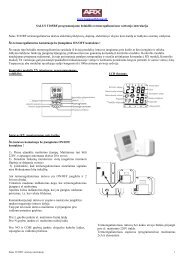
gas supply (methane or LPG) pressure must alsobe checked according to the type used in theboiler, as insufficient levels can reduce generatoroutput and cause malfunctions.Ensure correct gas cock connection. The gassupply pipe must be suitably dimensioned accordingto current regulations in order to guaranteecorrect gas flow to the boiler even in conditionsof maximum generator output and to guaranteeappliance efficiency (technical specifications).The coupling system must conform to standards.Combustible gas quality. The appliance has beendesigned to operate with gas free of impurities;otherwise it is advisable to fit special filters upstreamfrom the appliance to restore the purityof the gas.Storage tanks (in case of supply from LPGdepot).- New LPG storage tanks may contain residualinert gases (nitrogen) that degrade the mixturedelivered to the appliance casing functioninganomalies.- Due to the composition of the LPG mixture,layering of the mixture components may occurduring the period of storage in the tanks. Thiscan cause a variation in the heating power ofthe mixture delivered to the appliance, withsubsequent change in its performance.Hydraulic attachment.Important: In order not to void the warrantybefore making the boiler connections, carefullyclean the heating system on the primary heatexchanger (pipes, radiators, etc.) with specialpickling or de-scaling products to remove anydeposits that could compromise correct boileroperation.In compliance with Standards in force it is mandatoryto treat the water in the heating systemchemically in order to protect the system andappliance from deposits of lime scale.Water connections must be made in a rationalway using the couplings on the boiler template.The boiler safety valves outlet must be connectedto a draining funnel. Otherwise, the manufacturerdeclines any responsibility in case of floodingif the drain valves cut in.Important: to preserve the duration of applianceefficiency features, in the presence of water whosefeatures can lead to the deposit of lime scale,installation of the “polyphosphate dispenser” kitis recommended. On the basis of the Standards inforce, it is mandatory to treat the water with over25 French degrees in the heating circuit and over15 French degrees for DHW using conditioningchemicals for powers < 100 kW or with softenersfor powers > 100 kW.Electrical connection: The “Eolo Star <strong>24</strong> 3 E”boiler has an IPX5D protection rating for theentire appliance. Electrical safety of the unit isreached when it is correctly connected to anefficient earthing system as specified by currentsafety standards.Important: Immergas S.p.A. declines anyresponsibility for damage or physical injurycaused by failure to connect the boiler to anefficient earth system or failure to comply withthe reference standards.Also ensure that the electrical installationcorresponds to maximum absorbed powerspecifications as shown on the boiler data-plate.The boilers are supplied complete with an “X”type power cable without plug. The power supplycable must be connected to a 230V ±10% /50Hz mains supply respecting L-N polarity andearth connection , This network must alsohave a multi-pole circuit breaker with class IIIover-voltage category. When replacing the powersupply cable, contact a qualified technician (e.g.the Immergas After-Sales Technical AssistanceService). The power cable must be laid as shown.In the event of mains fuse replacement on thecontrol board, use a 3.15A quick-blow fuse. Forthe main power supply to the appliance, neveruse adapters, multiple sockets or extension leads.1.6 REMOTE CONTROLS ANDROOM CHRONOTHERMOSTATS(OPTIONAL).La caldaia è predisposta per l’applicazione deicronotermostati ambiente o dei comandi remotiche sono disponibili come kit optional.All Immergas chronothermostats are connectedwith 2 wires only. Carefully read the userand assembly instructions contained in theaccessory kit.• On/Off digital chronothermostat (Fig. 1-5). Thechronothermostat allows:- setarea a două valori de temperatură ambient:set two room temperature values: one for day(comfort temperature) and one for night(lower temperature);- set up to four on/off differential weekly programs;- select the desired function mode from thevarious possible alternatives:• permanent functioning in comfort temp.• permanent functioning in reduced temp.• permanent functioning in adjustable antifreezetemp.The chronothermostat is powered by two 1.5VLR 6 type alkaline batteries;• Digital Remote Control Device with climatechronothermostat function (Fig. 1.6). In additionto the functions described in the previouspoint, the Digital Remote Control panel enablesthe user to control all the important informationregarding operation of the appliance andthe heating system with the opportunity ofeasily intervening on the previously set parameterswithout having to go to the place wherethe appliance is installed. The Digital RemoteControl panel is provided with self-diagnosis todisplay any boiler functioning anomalies. Theclimate chronothermostat incorporated intothe remote panel enables the system deliverytemperature to be adjusted to the actual needsof the room being heated, in order to obtainthe desired room temperature with extremeprecision and therefore with evident saving inrunning costs. The chronothermostat is feddirectly by the boiler by means of the same 2wires used for the transmission of data betweenboiler and chronothermostat.Digital Remote Control or On/Off chronothermostatelectrical connections (Optional). Theoperations described below must be performed afterhaving removed the voltage from the appliance.Any thermostat or On/Off environment chronothermostatmust be connected to clamps 40and 41 eliminating jumper X40 (Fig. 3-2). Makesure that the On/Off thermostat contact is of the“clean” type, i.e. independent of the mains supply;otherwise the electronic adjustment card wouldbe damaged. The Digital Remote Control must beconnected to clamps 40 e 41 eliminating jumperX40 on the P.C.B. (in the boiler), (Fig. 3-2).Important: If the Digital Remote Control is used,arrange two separate lines in compliance withcurrent regulations regarding electrical systems.No boiler pipes must ever be used to earth theelectric system or telephone lines. Ensure eliminationof this risk before making the boilerelectrical connections.INSTALLATORUSERTECHNICIAN1-51-65 - IE