
Create successful ePaper yourself
Turn your PDF publications into a flip-book with our unique Google optimized e-Paper software.
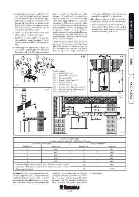
• Coupling of extension pipes and elbows. Toinstall snap-fit extensions with other elementsof the fume extraction elements assembly, proceedas follows: Install the pipe or elbow withthe male side (smooth) on the female section(with lip seal) to the end stop on the previouslyinstalled element. This will ensure sealing andjoining of the elements correctly.• Figure 1-27 shows the configuration withvertical exhaust and horizontal intake.• Installation clearances. Figure 1-26 gives themin. installation space dimensions of the Ø80/80 separator terminal kit in limited conditions.• Extensions for the separator kit Ø 80/80. Themax. vertical straight length (without bends)that can be used for Ø 80 intake and exhaustpipes is 41 metres of which 40 intake and 1exhaust. The total length corresponds to aresistance factor of 100. The total usable lengthobtained by adding the length of the intake andexhaust pipes Ø 80 must not exceed the valuesstated in the following table. If mixed accessoriesor components are used (e.g. changing froma separator Ø 80/80 to a concentric pipe), themaximum extension can be calculated by usinga resistance factor for each component or theequivalent length. The sum of these resistancefactors must not exceed 100.• Temperature loss in fume ducts. To preventproblems of fume condensate in the exhaustpipe Ø 80, due to fume cooling through thewall, the length of the pipe must be limited tojust 5 m. Fig. 1-28). If longer distances mustbe covered, use Ø 80 pipes with insulation (seeinsulated separator kit Ø 80/80 chapter).N.B.: when installing the Ø 80 ducts, a sectionclamp with pin must be installed every 3 metres.* The air intake pipe can be increased to 2.5metres if the exhaust bend is eliminated, 2metres if the air intake bend is eliminated, and4.5 metres eliminating both bends.INSTALLATOR71-251-279S415567A32C528C82The kit includes:N°1 - Exhaust gasket (1)N°1 - Female intake flange (3)N°1 - Flange gasket (2)N°1 - Female exhaust flange (4)N°2 - 90° bend Ø 80 (5)N°1 - Intake terminal Ø 80 (6)N°2 - Internal white wall sealing plates (7)N°1 - External grey wall sealing ring (8)N°1 - Exhaust pipe Ø 80 (9)1-26C42C82USERTECHNICIAN1-28Maximum usable length(including intake terminal with grill and two 90° bends)NON INSULATED PIPEINSULATED PIPEExhaust (m) Intake (m) Exhaust (m) Intake (m)1 36,0* 6 29,5*2 34,5* 7 28,0*3 33,0* 8 26,5*4 32,0* 9 25,5*5 30,5* 10 <strong>24</strong>,0** The air intake pipe can be increased to 2.5 metres if the exhaust bend is11 22,5*eliminated, 2 metres if the air intake bend is eliminated, and 4.5 metreseliminating both bends.12 21,5*Important: the boiler was designed to evacuatecombustion product up to a maximum extensionof 27 linear m to the exhaust, with 1 m plus 90°bend at intake. If installation requires an extensionof the flue fittings up to the exhaust thatexceeds the 12 m recommended, it is necessaryto properly consider the possibility that condensationmay form inside the duct and thereforeImmergas “Serie Blu” insulated flue fittings, orother flue fittings with similar characteristics,should be used.11 - IE