INSTALLATION INSTRUCTIONS Evaporator Coils - Alpine Home Air ...
INSTALLATION INSTRUCTIONS Evaporator Coils - Alpine Home Air ...
INSTALLATION INSTRUCTIONS Evaporator Coils - Alpine Home Air ...
- No tags were found...

Create successful ePaper yourself
Turn your PDF publications into a flip-book with our unique Google optimized e-Paper software.
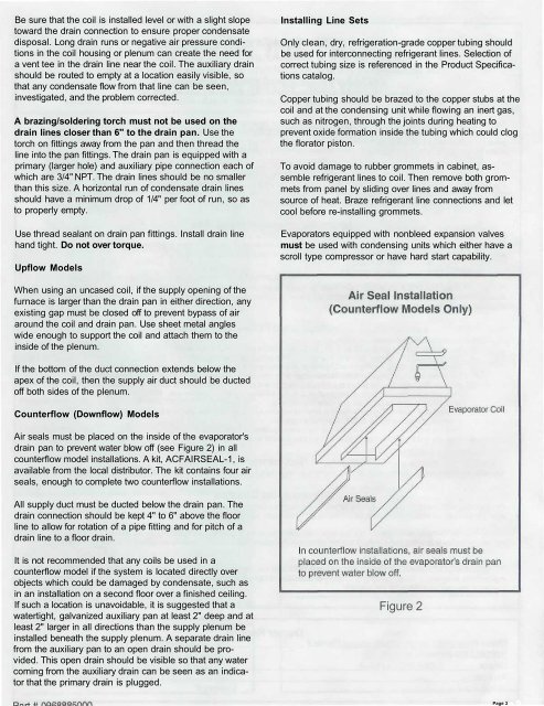
Page 3Be sure that the coil is installed level or with a slight slopetoward the drain connection to ensure proper condensatedisposal. Long drain runs or negative air pressure conditionsin the coil housing or plenum can create the need fora vent tee in the drain line near the coil. The auxiliary drainshould be routed to empty at a location easily visible, sothat any condensate flow from that line can be seen,investigated, and the problem corrected.A brazing/soldering torch must not be used on thedrain lines closer than 6" to the drain pan. Use thetorch on fittings away from the pan and then thread theline into the pan fittings. The drain pan is equipped with aprimary (larger hole) and auxiliary pipe connection each ofwhich are 3/4" NPT. The drain lines should be no smallerthan this size. A horizontal run of condensate drain linesshould have a minimum drop of 1/4" per foot of run, so asto properly empty.Use thread sealant on drain pan fittings. Install drain linehand tight. Do not over torque.Upflow ModelsInstalling Line SetsOnly clean, dry, refrigeration-grade copper tubing shouldbe used for interconnecting refrigerant lines. Selection ofcorrect tubing size is referenced in the Product Specificationscatalog.Copper tubing should be brazed to the copper stubs at thecoil and at the condensing unit while flowing an inert gas,such as nitrogen, through the joints during heating toprevent oxide formation inside the tubing which could clogthe florator piston.To avoid damage to rubber grommets in cabinet, assemblerefrigerant lines to coil. Then remove both grommetsfrom panel by sliding over lines and away fromsource of heat. Braze refrigerant line connections and letcool before re-installing grommets.<strong>Evaporator</strong>s equipped with nonbleed expansion valvesmust be used with condensing units which either have ascroll type compressor or have hard start capability.When using an uncased coil, if the supply opening of thefurnace is larger than the drain pan in either direction, anyexisting gap must be closed off to prevent bypass of airaround the coil and drain pan. Use sheet metal angleswide enough to support the coil and attach them to theinside of the plenum.If the bottom of the duct connection extends below theapex of the coil, then the supply air duct should be ductedoff both sides of the plenum.Counterflow (Downflow) Models<strong>Air</strong> seals must be placed on the inside of the evaporator'sdrain pan to prevent water blow off (see Figure 2) in allcounterflow model installations. A kit, ACFAIRSEAL-1, isavailable from the local distributor. The kit contains four airseals, enough to complete two counterflow installations.All supply duct must be ducted below the drain pan. Thedrain connection should be kept 4" to 6" above the floorline to allow for rotation of a pipe fitting and for pitch of adrain line to a floor drain.It is not recommended that any coils be used in acounterflow model if the system is located directly overobjects which could be damaged by condensate, such asin an installation on a second floor over a finished ceiling.If such a location is unavoidable, it is suggested that awatertight, galvanized auxiliary pan at least 2" deep and atleast 2" larger in all directions than the supply plenum beinstalled beneath the supply plenum. A separate drain linefrom the auxiliary pan to an open drain should be provided.This open drain should be visible so that any watercoming from the auxiliary drain can be seen as an indicatorthat the primary drain is plugged.Figure 2

![Owner's Manual (General) [pdf] - Appliance Factory Parts](https://img.yumpu.com/50830858/1/184x260/owners-manual-general-pdf-appliance-factory-parts.jpg?quality=85)