Create successful ePaper yourself
Turn your PDF publications into a flip-book with our unique Google optimized e-Paper software.
1. GENERAL WARNINGREAD THIS GENERAL WARNING FIRSTIN SUSPENDED SCAFFOLD OPERATIONS, SAFETY IS A MATTER OF LIFE OR DEATHFOR RIGGERS, OPERATORS AND BY-STANDERS.THIS WARNING IS YOUR SHARE OF DUTIES FOR ACHIEVING SAFETY.YOUR DUTY TO UNDERSTAND AND COMPLY1. It is the rigger’s and the operator’s responsibility,and their employer’s responsibility, if they operateunder an employer’s control, to strictly conform tothe following warnings.2. It is imperative for safety and efficiency of the operationsthat this manual be read and fullyunderstood by the rigger and the operator beforerigging or operating the TIRAK ® . ALL instructionscontained herein must be carefully and strictlyfollowed, including applicable S.I.A. guidelines forsafe practice (see pages 38 and 39).3. Should you hand over a TIRAK ® , under whateverconditions, to any party operating out of your control,you must join a clean copy of this manual anddraw other party’s attention that strictly following allthe instructions therein is a matter of life or death.4. Before rigging and operating this TIRAK ® hoist, therigger and the operator must become awareof all the requirements of federal, state, provincialand local safety regulations not only applicable tothe TIRAK ® hoist but also to the entire suspendedscaffold system and any component of it.5. Never use the TIRAK ® hoist for any job other thanlifting personnel on suspended scaffold accordingto the instructions of this manual6. Never load the TIRAK ® hoist above its rated load.YOUR DUTY TO INSPECT AND MAINTAIN7. Keep this manual available at all times for easyreference whenever required. Extra copies are availablefrom the supplier.8. Carefully take notice of all the labels affixed to theTIRAK ® . Never rig or operate the hoist if any label,normally fixed on the hoist is obscured or missing(see page 35 and 36). The supplier will supply extralabels on customer’s request.9. Every time the hoist is to be rigged or used, checkthat the hoist, wire rope and other components ofthe suspended scaffold system are complete and ingood working condition, prior to proceeding.10. A careful and regular inspection of the TIRAK ® hoist,its wire rope and other components of the installationis part of the safety requirements. If you haveany questions, call the supplier.11. After each de-rigging and before re-rigging, theTIRAK ® must be inspected by a competent personfamiliar with the TIRAK ® hoist and professionallytrained for the purpose.YOUR DUTY TO TRAIN AND CONTROL PEOPLE12. An operator must not be assigned to a suspendedjob or to rigging for a suspended job, or to deriggingafter the job, if that person is not:a) mentally and physically fit for the purpose, speciallyat heights,b) competent for the job to be performed,c) familiar with all applicable safety rules and requirements,d) familiar with the scaffold equipment as rigged,e) provisionally trained for working under the aboverequirements.13. Never disassemble the TIRAK ® by yourself or byyour staff. People’s life may be at risk.Except for the operations described in this manual,the maintenance of the TIRAK ® hoists, as well asdisassembly and repair, must be exclusively doneby qualified repairers authorized in writing by thesupplier. TIRAK ® spare parts in accordance with theserial number of each machine must be exclusivelyutilized. No substitutions are allowed.14. Never let the TIRAK ® hoist and other equipment of asuspended scaffold system be managed or operatedby a person other than authorized and assignedto the job. Keep the equipment, either rigged orunrigged, out of reach of unauthorized persons, whileout of operation.4
15. Training operators and riggers includes setting uprescue procedure should a scaffold be brought to astandstill during a job. Such procedure must be setup by a competent person of the user, or of itstechnical consultant, according to the working conditions,prior to putting the equipment into operation.16. Every suspended job must be placed under thecontrol of a person having the required competenceand the authority for checking that all the instructionsprescribed by this manual be regularly andefficiently carried out.YOUR DUTY OF SAFETY BEYOND THE TIRAKAs being only one piece of the scaffold system, theTIRAK ® hoist can contribute to the required safety only,if …:17. … it is fitted on compatible scaffold equipment, includingthe wire rope used in the TIRAK ® hoist.18. … other components meet the requirements of theapplicable safety regulations and are of the properquality, and assembled to form a safe suspendedscaffold system.19. … every upper support of the scaffold is stable,sufficiently strong and properly tied back to the structure,according to the load either static or dynamic.20. … supporting structure and tie-back provide the requestedresistance to every load to be applied, eitherstatic or dynamic, during rigging or operating thescaffold equipment;21. … all the requirements in strength and resistanceare obtained with the necessary safety factor (seeregulations and professional standards);22. … all the calculations, design and subsequent worknecessary to the above requirements have beenmade by a competent person on the basis of propertechnical information regarding the site.YOUR DUTY TO AVOID TAKING CHANCES23. The BLOCSTOP ® BSO or BS/BSO secondary brakelocated at the upper part of the unit is an integralpiece of the TIRAK ® hoist. It is strictly forbidden todetach it from the main body of the hoist for whateverreason. Doing so would be a misuse creatingan extreme hazard and placing operators and bystandersin danger of death resulting from thepossible fall of the suspended equipment: scaffold,workcage, bosun’s chair or any other items or components.24. Once the suspended scaffold, work-cage or bosun’schair has been lifted off its initial support (ground orany other level), it is imperative not to release, remove,alter or obstruct any part of the equipmentunder load.25. NEVER allow any condition which would result in asuspension wire rope becoming SLACK during theoperation, unless …:a) … the suspended scaffold, work-cage or bosun’schair is supported on a safe surface giving a safeaccess to the operator in compliance with safetyregulations, or unless …b) … another suspension wire rope has been safelyrigged to the suspended scaffold, workcage orbosun’s chair.26. Never operate the TIRAK ® hoist and its accessories,especially electric ones, in a potentiallyexplosive atmosphere.27. For any job to be performed on the suspendedequipment, consider and control the specific risksrelated to the nature of the job.28. Should you decide that the TIRAK ® hoist is no longerto be used, take precautions in disposing of it sothat it cannot be used any more.AN ULTIMATE RECOMMENDATIONNever neglect means to improve safety. Due to the risks inherent in the use of suspended scaffold systems, thesupplier strongly recommends that every installation be equipped with secondary wire rope(s) fitted with aseparate fall arrest system. Details about TIRAK ® with BLOCSTOP ® BS/BSO secondary brake on 2 wire ropesystems at pages 21 to 34.This manual is neither a regulations compliance manual nor a general training guide on suspended scaffoldoperations. You must refer to proper instructions delivered by manufacturers of the other pieces of equipmentincluded in your suspended scaffold installation. Whenever calculations and specific rigging and handling areinvolved, the operator should be professionally trained to that end and secure relevant information prior tocommencing such work.5
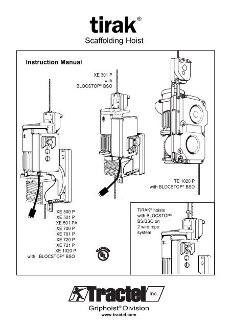
2. DESCRIPTIONFigure 22.1 Motor and Primary BrakeTIRAK ® hoists are driven by a single phase ora three phase motor, totally enclosed fancooled (TEFC) type with an electromagneticbrake. Pneumatic TIRAK ® hoists are availablealso.Dd1d2TE 1020 PwithBLOCSTOP ®BSO2.2 Gear ReducerThe gear reducer consists of a worm geardrive in connection with a spur gear, oil bathlubricated in a sealed aluminum casing.c4CADXE 301 PwithBLOCSTOP ®BSO2.3 Secondary BrakesThe BLOCSTOP ® BSO overspeed locking device(D) – hereafter called BSO secondarybrake – stops the descent immediately incase of accelerating overspeed.The BLOCSTOP ® BS/BSO overspeed andslack wire rope locking device (E) – hereaftercalled BS/BSO secondary brake –additionally provides protection against slackwire rope or primary wire rope failure, whenusing secondary wire ropes.SECONDARY BRAKES MUST ALWAYS BEATTACHED AND USED.BDCBa1c1c3c2Ac42.4 Emergency Descentwithout powerTIRAK ® hoists are equipped with a mechanicalcentrifugal braking system, permitting adescent at moderate speed in case of emergency.No handcranking is needed.2.5 Wire Rope Driving MechanismThe wire rope enters the hoist from the top, isled through by the patented driving system,and exits opposite its entry. As the wire ropeis not stored inside the hoist, its length (i. e.the possible rope travel) is unlimited on principle.The driving system is independent of the loadapplied to the wire rope. The whole mechanismis housed in an aluminum casing.CBc1c3c2Ac4a1XE 501 PXE 501 PAXE 500 PXE 701 PXE 700 PXE 721 PXE 720 PXE 1020 Pwith BLOCSTOP ® BSOTIRAK ® hoistswith BLOCSTOP ®BS/BSO on2 wire ropesystemE2.6 Wire RopeTIRAK ® hoists use a Special TIRAK ® WireRope (see chapter 4). Unless specificly specifiedin writing by the manufacturer, only thisspecial TIRAK ® Wire Rope may be used.NOTE: The manufacturer declines all responsibilityfor machines used witha wire rope other than specified bythem in writing.ABCWire rope driving mechanisma1 Stirrup adapter (X-Series)GearboxMotor with brakec1 Electric control boxc2 Push button controlc3 Electric EMERGENCY STOPc4 Emergency descent brakerelease lever (stored position)DEBLOCSTOP BSOsecondary braked1 Control leverd2 EMERGENCY STOPon the BLOCSTOPBLOCSTOP ® BS/BSOsecondary brake6
EMERGENCYYEMERGENC2.7 Technical DataFigure 3DimensionsXE 301 Pwith BLOCSTOP ® BSOXE 500 PXE 501 PXE 501 PAXE 700 PXE 701 PXE 720 PXE 721 PXE 1020 Pwith BLOCSTOP ® BSOTE 1020 Pwith BLOCSTOP ® BSOaaUPDOWaSTOPUPDOWNbcbcbc<strong>Hoist</strong> Model XE 301 P XE 501 P XE 501 PA XE 500 P XE 701 P XE 700 P XE 721 P XE 720 P XE 1020 P TE 1020 Pwith BLOCSTOP ® model BSO 500 BSO 1020Rated load lbs 700 1,000 1,000 1,000 1,500 1,500 1,500 1,500 2,200 2,000kg 315 450 450 450 680 680 680 680 1,000 900Lifting speed ft/min 33 35 35 35 35 35 35 35 35 35m/min 10 11 11 11 11 11 11 11 11 11Weight (with BSO) lbs 82 123 121 106 123 112 126 115 120 178kg 37 56 55 48 56 51 57 52 54 81Dimensions over alla in. 28.9 31.8 31.8 31.8 31.8 31.8 33.3 33.3 33.3 34.6mm 735 808 808 808 808 808 845 845 845 879b in. 11.2 12.9 12.5 12.1 13.2 12.5 13.2 12.5 12.5 14.8mm 286 328 318 308 336 318 336 318 318 375c in. 12.5 15.8 14.1 14.1 14.9 14.1 14.9 14.1 14.1 14.6mm 314 402 357 357 379 357 379 357 357 371Motor specificationselectrical motor3-phase 220 V/60 cycles kW – – – 1.1 – 1.5 – 1.5 2.4 2.2A – – – 4.5 – 6.1 – 6.1 9.6 9.5single phase:110 (or 220 V)/ 60 cycles kW 0.55 1.1 – – – – – – – –A 10.0 19.0/(8.5) – – – – – – – –220 V/ 60 cycles kW 0.55 – 1.1 – 1.5 – 1.5 – – –A 4.8 – 8.5 – 12.0 – 12.0 – – –wire rope in. 5/16 3/8diameter mm 8.4 9.5wire rope classification/5 x 19, 4 x 26, or 5 x 26, with fiber core, or 6 x 19 (min. 17 wiresconstructionper strand), galvanized or black, lubricated, preformed, IPS or XIPSnominal diameter in./mm 5/16 in. / 8.4 mm 3/8 in. / 9.5 mmmaximum allowed in. 0.319 to 0.331 0.362 to 0.374diameter tolerances mm 8.1 to 8.4 9.2 to 9.5minimum actual lbs 10,000 15,000breaking strength kN 44.5 66.87
3. RIGGING INSTRUCTIONSFig. 4 Relevant Items (principle sketch)3.1 GENERAL3.1.1 ScopeInstructions and advice in this manual exclusively referto the following items (see Fig. 4):– TIRAK scaffold hoistwith BLOCSTOP ® BSO secondary brakeor BS/BSO 1) secondary brake;– Special TIRAK wire rope;– Power supply cord.Fixing thewire rope to thesupport equipmentSpecialTIRAK ® wire ropeTIRAK ® withBLOCSTOP ® BSOsecondary brake1) Instructions and advice for TIRAK ®with BLOCSTOP ® BS/BSOsecondary brakesee seperate instructionson pages 21 to 34.ConnectingTIRAK ® andplatform systemPowersupply cordFig. 5Typical suspended scaffold installationTie-backSupportequipmentLifeline3.1.2 Checks before riggingIt is a qualified person’s responsibility to check the wholeinstallation to meet all safety requirements of:– OSHA regulations and federal, state, provincial orlocal safety regulations,– the proper instructions delivered by the manufacturersof the other pieces of equipment included inyour suspended scaffold installation.Some pieces are:– Support equipment including tie-back;– platform system, work-cage, or bosun’s chair;– safety equipments (personal fall arrest system);– barricade below the drop of the platform/workcage/bosun’schair.SpecialTIRAK ®wire ropeTIRAK ®withBLOCSTOP ®BSOSuspendedplatformsystemPersonalFall ArrestSystemPowersupplycordNOTE: This information is NOT to be considered asa complete checklist for your specific installation.It is only a sample list of some general components,which make part of a typical suspendedscaffold installation (Fig. 5).8Barricade
3.2 Power Supply and <strong>Hoist</strong> Control3.2.1 General(1) Check if voltage indicated on the hoist nameplatecorresponds to the power supply rating.(2) Single phase motors are factory connected foreither 220 VAC or 110 VAC.On dual voltage machines change plug and wiringaccording to drawing inside control box.Three phase machines are factory connected for220 VAC, 3 Ø.(3) It is important to note that SINGLE-PHASE motorsare more sensitive to overloading and voltage dropthan three phase motors.Therefore never exceed maximum rated load, andsee to it that the 110/220 VAC power supply isalways available.In case of difficulties have an electrician or qualifiedperson read voltage at motor terminal during liftingoperation. Especially for high lifting operations, whichrequire long cords, it is essential to use power cordsof sufficient size (see par. 3.2.3) to avoid excessivevoltage drop.(4) WARNING: NEVER OPERATE THE HOISTOR ANY OTHER ELECTRIC EQUIP-MENT IN A POTENTIALLY EXPLOSIVEATMOSPHERE: around distilleries, refineries,chemical plants, ship or silointeriors.Always obtain official approval before commencingoperations at these or similar locations.(2) In some cases, a booster transformer will be neededto compensate for power cord losses or low-sourcevoltage. If a booster transformer is needed, call supplier.(3) CAUTION: DO NOT OPERATE THE MOTORFOR ANY REASONS, IF THE MEAS-URED RUN VOLTAGE IS LESSTHAN THE MOTOR NAMEPLATERATING!(4) Always secure the powercord to the platform with astrain relief fitting andshackle (Fig. 7), so thecord weight will be off theconnector.(5) When finished for the day,make certain the powercord is disconnected at thehoist pigtail as well as atthe main outlet.(6) Be sure to ground all electricequipment. D onot use wire rope as aground!Fig. 6 Strain ReliefFitting3.2.2 Fuses / Circuit breakersIf connected to a circuit protected by a fuse, use Time-Delay-Fuse.Check if specification of fuses, which protect electricalequipment, corresponds to the amperage indicated onthe machine nameplate. The recommended service requirementsper hoist are:3.2.4 <strong>Hoist</strong> ControlControl (Fig. 7) is by– push-buttons, which automatically return intoSTOP-position, when not activated, and an– EMERGENCY STOP button.DO NOT fix push-buttons in run position.Single phase Three phase amps.110 V 220 V 30220 V – 203.2.3 Power Cords and Grounding(1) To prevent voltage drop exceeding the allowable10% we recommend to use at least #10, STO typepower cords, 600 VAC rating.To minimize voltage drop due to power cord lengthon high lifts, select an outlet at the halfway point toreduce the total power cord length on the job.Fig. 7Typical <strong>Hoist</strong> Control9
3.3 <strong>Hoist</strong> Mounting3.3.1 TIRAK ® X-seriesBolt the hoist to platform stirrup usingstirrup adapter, which alsoholds the hoist in its upright position(see Figs. 8 and 10).Figure 8<strong>Hoist</strong> mountingTIRAK ®X-series90°Figure 9<strong>Hoist</strong> mountingTIRAK ®T-series90°Use two 1/2 inch diameter grade 5or better bolts with locking nuts.WARNING:HOIST CONNECTIONBOLTS MUST NOTBEAR ON THREADS.3.3.2 TIRAK ® T-seriesFix the hoist using its anchor pin(see Fig. 9 and 11). Make sure thatthe hoist is held in its upright positionby means of an appropriatesupport. The anchoring device mustattach to the pin between the 2 castears “b” of Fig. 11.StirrupadapterWARNING:THE HOIST MUST BE MOUNTED SUCHTHAT THE WIRE ROPE PERPENDICU-LARLY ENTERS THE HOIST.Figure 11StirrupAnchorpinDimensions of connecting partsTIRAK ® T-series90°(Figs. 8 and 9)Figure 10Dimensions of connecting parts (stirrup adapter)TIRAK ® X-seriesXE 301 PAnchor pin Ø:0.63 in. / 16 mmAnchor hole Ø:0.65 in. / 16.5 mmb baa = 1.1 in. / 28 mmb = 0.55 in. / 14 mma 1 efa 3Ø dbcFigure 12Special rigging arrangementa 2X 500/700/1000seriesefba 1= 4.41 in. / 112 mma 2= 3.94 in. / 100 mma 3= 3.86 in. / 98 mmb = 1.58 in. / 40 mmØ da 3cc = 0.47 in. / 12 mmd = 0.51 in. / 13 mme = 1.36 in. / 32 mmf = 1.02 in. / 26 mmNOTE: Any rigging arrangementotherthan describedin this manual isentirely underthe rigger’s responsibility.For special projects likeshown in this figure contactthe supplier foradditional information.10
4. Wire Rope4.1 Wire rope specificationUse only wire ropes specified by the manufacturer:(1) Classification/Construction:5x19, 4x26, or 5x26, with fiber core, or 6x19,(min. 17 wires/strand), galvanized or black,lubricated, preformed IPS or XIPS.Table 3: Wire Rope Diameter and min. actual Breaking Strengthwire min. actual for TIRAK ® hoistsrope breaking withdiameter 1) strength rated load up to(2) Diameter:NOTE: Correct wire rope diameter is very importantfor the TIRAK ® function! An oversizedwire rope may cause the BSO or BS/BSOsecondary brake to malfunction.NOTE: How to measure wire rope diameter:The correct diameter of the wire rope is thelargest cross-sectional measurement acrossthe strands (and not the valleys).The measurement should be made carefully withcalipers as shown in Fig. 13.5/16 in. 10,000 lbs 1,500 lbs8.4 mm 44.5 kN 680 kg3/8 in. 15,000 lbs 2,200 lbs9.5 mm 66.8 kN 1,000 kg1) Maximum allowed tolerances of NEW wire rope diameter:5/16 in. (8.4 mm) = 0.319 to 0.331 in. (8.1 to 8.4 mm)3/8 in. (9.5 mm) = 0.362 to 0.374 in. (9.2 to 9.5 mm)4.2 Wire rope rigging instructionsWARNING:Be sure to use a wire rope with thediameter marked on the TIRAK ®nameplate.Figure 13 Checking Wire Rope Diameter “d”d(1) RIG FROM TOP.You should have enough wire rope to reach to theground or other safe level with about five feet (1.5 m)extra for ensuring safety.CAUTION:Always unreel and reel the wire rope ina straight line (Fig. 14) to prevent kinks,which make it unusable for the hoist.Figure 14 Wire Rope HandlingIncorrectCORRECT11
4.2 Wire rope rigging instructions(continued)(2) If the wire rope is not equipped with a swaged fittingas shown in Fig. 15, proceed as follows:– Install heavy duty thimble with a minimum of three(3) J-Type (Fist Grip) Clamps (Fig. 16).– Apply first clamp approximately 7" (18 cm) fromthimble. Tighten nuts moderately.– Attach second clamp as close to thimble as possible.Leave nuts loose.– Attach the third clamp half-way between first andsecond clamp, leaving the nuts loose. Take up wirerope slack.– Tighten nuts evenly on all clamps (approx. 30 ft-lbs.torque) as specified by the clamp manufacturer.WARNINGS:a) Retighten after the wire rope isloaded for the first timeb) Inspect fastening periodically.In use, wire ropes will stretch and reduce indiameter.Retighten all “Fist Grip” nuts periodically.(3) Anchor the wire rope end to a rigging device, whichcomplies with all relevant safety requirements.Be sure to use compatible connecting devices, e. g.a 1/2 in. anchor shackle or similar with adequatestrength and safety factor. Secure it.Figure 15Wire Rope Terminationby Swaged FittingHeavy dutythimbleFerrule(Sleeve)Figure 16Wire Rope Terminationby Fist Grip ClampsHeavy duty thimbleFist Grip ClampFigure 17Suspension Distance(4) Insure that the anchor points of the wire rope aredirectly above the position of the hoists (Fig. 17).WARNING:Improper spacing is dangerousand could cause failureof the support system.Same distance XXPlatformSupportsystem<strong>Hoist</strong>(5) Check that wire rope tip is welded round (Fig. 18).IF NOT:a) Prepare ends by brazing or welding – makesure all end wires are captured.b) Grind end to approximately 1/4" diameter.DO NOT grind end flat or to a cone shape.End must be rounded (Fig. 18).c) The last 4 in. (10 cm) of wire rope must bestraight for proper reeving.12Figure 18 Wire Rope Tip4 in. (10 cm) Straightmax.1 1 /2 dia.dia.
YEMERGENC4.3 Wire rope reevingFigure 19Opening of BSO Secondary Brake(1) Open the BSO secondary brake by pushing downthe control lever (d1) until it locks (Fig. 19).(2) Push the rope through the BSO secondary brake at(A) into the hoist rope inlet (B).Push it inside, and press UP-button, until the wirerope reeves itself automatically and exits at (C) onthe other side (Fig. 20).CAUTION:Check that wire rope exit (C) is not blockedin any manner.Never load the wire rope exiting from (C).(d1) Closed(d1) OPENFigure 20Wire Rope Reeving(A)TIRAK ® Entrance wire ropeTIRAK ®X-seriesT-series(A)(A)(B)(B)(B)STOPUPDOWN(C)(C)Exit wire ropeMust not be loaded!(C)(C)(3) After reeving through the hoist, be sure to loop andclamp the free end of the wire rope, to prevent therope from inadvertently unreeving through the hoist.Always tie this loop, using a fist grip clamp, whenthe platform is at ground level or other safe surface(Fig. 21).WARNING:AT EVERY SET-UP OR RERIGGING checkthe wire rope length to ensure that itreaches the ground or other safe levelwith about five feet (1.5 m) extra forsafety.Figure 21 Loop at Free Wire Rope EndBottom free endof wire ropeFistGripClamp13
4.4 De-Rigging(1) Before de-rigging each TIRAK ® hoist must beunloaded by bringing down the platform to a safeand stable support.(2) Remove the loop at the free wire rope end.(3) Press DOWN button to let the wire rope run out.(4) With gloved hands slowly pull the wire rope throughBSO secondary brake.(5) Clean the wire rope, reel it (Fig. 22), and store it in aclean and dry place.Figure 22 Wire Rope Handling5. Operating Instructions5.1 GENERAL(1) BE FAMILIAR with the equipment and its propercare.DO NOT operate hoist, if adjustment or repairs arenecessary, if any warning, operating or capacitylabel normally attached to the hoist is obscured,damaged, or missing. (See labels’ list on page 35).REPORT same promptly to your supervisor andalso notify next operator, when changing shifts.Figure 23BSO Secondary BrakeCheck IEMERGENCYSTOP (d2)(d1) Closed(d1) OPEN(2) WARNING: SAFETY DEMANDSTHAT YOU TEST THE SYSTEMBEFORE GOING ALOFT:14a) CHECK PLATFORM fully rigged and loaded bycycling UP and DOWN several times near groundlevel or safe surface.b) CHECK PRIMARY BRAKE for mechanical function:When stopping the hoist the load must beheld immediately.c) CHECK BSO SECONDARY BRAKE:IIIAt ground level first close the BSO secondarybrake by pushing EMERGENCY STOP button(d2). Then push control lever (d1) in DOWNpositionand make the wire rope form a loopbetween TIRAK ® casing and BSO secondarybrake (Fig. 23). Open BSO secondary brake bypulling down control lever (d1) until it locks in theopen position.With gloved hands sharply pull wire rope in arrowdirection (Fig. 23) – the BSO secondarybrake should close immediately (Fig. 24). ResetBSO secondary brake by pushing down controllever (d1) until it locks in the open position.Lift platform 3 ft. (1 m) above ground or safesurface, and push EMERGENCY STOP button(d2) of the BSO secondary brake (Fig. 24).Lower the platform to check that the BSO secondarybrake holds the load. A loop should formas shown in Fig. 23, which means the BSO secondarybrake is supporting the load.Figure 24BSO Secondary BrakeChecks II + IIIEMERGENCYSTOP (d2)Wire rope loop(d1) CLOSED(d1) Open(d3) WindowRaise platform until the hoist supports the load.Reset (d1) to the open position.III During operation regularly check through the window(d3) that the centrifugal weights are rotating(Fig. 24).WARNING:IF DURING ONE OF THE CHECKSTHE BSO SECONDARY BRAKEMALFUNCTIONS, IT MUST BEREPLACED.
d) Ceck EMERGENCY STOP button and pushbuttoncontrol (Fig. 25)i) Check that the UP and DOWN pushbuttonsreturn to their normal open position when released.They should move freely withoutsticking.ii) Push the red EMERGENCY STOP button. Itshould lock and remain depressed. Now trypushing the UP or DOWN pushbutton – themotor should not turn.Twist the EMERGENCY STOP button in thearrow direction to disengage it – it shouldpop out, and the hoist should now operatenormally.Repeat this check a few times to check functionof pushbuttons and the EMERGENCY STOP.WARNING:If the pushbuttons or EMERGENCYSTOP button do not function properly,remove hoist from service untilrepaired by a qualified person.Fig. 25 Typical <strong>Hoist</strong> Controle) CONTINUOUSLY CHECK rigging, lines, clearances,and all other elements throughout theentire time on the job.5.2 Normal operation(1) For UP and DOWNWARD MOTION of the platformjust press the corresponding button.(2) When operating platform, take care to operate hoistsso that the platform stays level without tilting oneend more than the other.(3) WARNINGSa) DO NOT fix push-buttons in run position.b) DO NOT operate the hoist, if it is functioningimproperly, or damage is noted.c) NEVER pick up a load beyond the ratedcapacity appearing on the hoist.d) STOP OPERATIONS IMMEDIATELY, if atany time, when the hoist operates, the wirerope does not move (i.e. no UP or DOWNtravel).It is likely that damaged wire rope is jammingthe hoist. Continued operation mightcause wire rope failure or damage to thehoist.CONTACT the SUPPLIER!e) IN CASE OF AN INCIDENT involving injury,or property damage, contact the supplierimmediately.DO NOT disturb, alter, or move any equipmentat the scene of the incident.f) OPERATING IN EXPLOSIVE ATMOS-PHERE: Never operate hoist or any otherelectric equipment in a potentially explosiveatmosphere – such as around distilleries,refineries, chemical plants, ship orsilo interiors. Always obtain official approvalbefore commencing operations atthese or similar locations.(4) Special Operating Notes for Welding orArc scarfing– ALWAYS PROTECT your equipment and yourselffrom the danger of arcing.– BE SURE supporting equipment is grounded toprevent arcing across wire rope to the structure.– DO NOT use wire rope as a ground for welding.– DO NOT allow your welding gun to contact wirerope, hoist, or any other metal equipment or structure.– PROTECT work area above and below hoist withinsulation.Split a section of air rubber hose, and wrap aroundwire ropes.– Use an insulated thimble assembly to attach allwire rope(s) to the suspension system.15
5.3 Emergency DescentIn case of emergency you can descend with the platformwithout power proceeding as follows:(1) Take the brake release lever (A) from the carryinghandle, and insert it through the motor fan coverhole into the brake release bow. Lift in arrow direction(Fig. 26). The hoist begins to lower at moderatespeed, which is regulated by a mechanical centrifugalbrake.(2) To STOP just release the lever.(3) After use: restore brake release lever (A) into itsstorage position.CAUTION:DO NOT USE EMERGENCY DESCENTAS REGULAR TECHNIQUE TO LOWER.Figure 26ABrake ReleaseBCIf during emergency descent the BSO secondary brake has been activated, proceed as follows:– Remove rubber cap (B) from motor fan cover,take hand wheel (C) from its support on the TIRAK ®casing, and place it on the motor shaft (Fig. 26).– With the brake opened (see above) turn the handwheel clockwise (T-series) resp. counter-clockwise(X-series) until the hoist supports the load.– Reset BSO secondary brake by pushing controllever (d1) in the OPEN position (Fig. 27).– Restore hand wheel (C) into its storage position,and put back rubber cap (B) on the motor fan cover.– Continue with manual descent.5.4 BSO Secondary Brake Action(1) EMERGENCY STOPPush EMERGENCY STOP button of the BSO Secondarybrake, if – for whatever reason – you wantto absolutely stop downward travel of the platform.(2) To reset BSO secondary brake:Raise the platform until the hoist supports the load.Push the control lever in the OPEN position (d1)(Fig. 27). DO NOT force it open.(3) If the BSO secondary brake has automaticallyclosed:Figure 27BSO Secondary BrakeEMERGENCYSTOP (d2)(d1) Closed(d1) OPENWARNING: STOP DOWNWARD TRAVEL! YOUMAY HAVE RUN OFF THE WIRE ROPECAUSING OVERSPEED. WITH EX-TREME CAUTION TRY TO GO UP.IF YOU CANNOT GO UP, A RESCUE IS RE-QUIRED.When the hoist supports the load, reset the BSOsecondary brake as described above.CAUTION: If the BSO secondary brake repeatedlystops downward travel, contactthe supplier for advice. Check wirerope diameter (see page 11).WARNING:DURING USE OF THE HOIST NEVERDETACH BSO SECONDARY BRAKE!16
6. TROUBLE SHOOTINGWARNINGS!Avoid injuries:1. Checks and repair of the electric equipmentmust only be carried out by QUALIFIED ELEC-TRICIANS!Wiring diagrams are found in the control boxof the motor.2. DO NOT OPEN ANY CONTROL BOX OR PEN-DANT CONTROL WITH POWER SUPPLY TOHOIST!3. Any other repair should only be carried outby the supplier (TRACTEL Group Company)or by a qualified person, and only originalspare parts shall be used.6.1 Wire Rope Drive Mechanism TroublesProblem Cause RemedyWire rope does not movethrough, i. e. no UP norDOWN movement.It is likely that damaged wire ropeis jamming the hoist.WARNING: STOP OPERATIONSIMMEDIATELY!Continued operation might causewire rope failure.Contact the supplier.6.2 Motor TroublesProblem Cause Remedy1. Motor does not runat all.a) Power failure a) Check fuses, power cords, connec-tions,and starting capacitor.b) Incorrect wiring b) Compare wiring with wiring diagram.c) On 3 phase motor: stop by thephase control relayc) Check wiring.2. Motor does not start a) Overload a) Check load and reduce, if necessary.with a load.b) Brake not released b) Check motor with brake released by hand.Check brake according to para. 5.1 (2), page 14.c) Voltage too low c) Check voltage when running the motor.Use power cord(s) with higher cross section.d) Incorrect wiring d) Compare wiring with wiring diagram.3. Motor stallsunder load.Low voltage Check voltage when running the motor.Use power cord(s) with higher cross sections.4. Overheating a) Insufficient cooling a) Clean motor fan cover.when runningwithout load b) Incorrect wiring b) Compare wiring with wiring diagram.c) Voltage too high c) Check voltage and no-load current.d) Short circuit in the coil d) Contact the supplier.5. Overheating a) Overload a) Check load and reduce if necessary.b) High or low voltage b) Check current consumption, and´compare with motorlabel specifications. Check current and voltage.Check power cordsc) Starting capacitor c) Check current at the auxiliary winding in the control box,still activated.when running the motor.Centrifugal switch defect.For centrifugal switch repair contact the supplier.d) Crooked motor shaft. d) Contact the supplier.e) Brake not (correctly) released. e) Check brake according para. 6.3.6. Abnormal motor noise a) Electric parts a) Causes/remedies see above 1. to 5.(noise disappearing immediately, when stopping motor)b) Mechanical parts b) Contact the supplier.(noise continuous until hoist stands still)17
6.3 Primary Brake TroublesProblem Cause RemedyBrake does not open a) Defective supply conductor, a) Have supply conductor, current passage in brake coil,(lack of “click” switch noise, brake coil, rectifier. rectifier checked by an electrician or qualified person.when starting/stopping thehoist) b) Worn brake rotor b) Contact the supplier.6.4 BSO Secondary Brake TroublesProblem Cause Remedy1. <strong>Hoist</strong> goes up BSO secondary brake is closed: WARNING: STOP DOWNWARD TRAVEL!but not down. Primary wire rope has run out Proceed according para. 5.4, (3), page 16.or has failed.2. BSO secondary brake a) Mechanical defect. a) Contact the supplier.automatically closeswithout apparent reason. b) Oversized or damaged wire rope b) Check wire rope and replace, if necessary.If you cannot find a trouble’s cause, contact the supplier.7. INSPECTIONS and MAINTENANCENOTE: A maintenance program should start foreach hoist immediately after it is enteredinto service.Regular inspections should be followed forthe life of the hoist and written inspectionrecords kept as specified.This maintenance program should complywith recommendations in the applicable parts andInstruction Manual, and all pertinant Federal, State,Provincial and Local regulations.7.1 Inspections7.1.1 DAILY INSPECTIONSEACH DAY PRIOR TO USE AND DURING OPERA-TION CHECK:(1) Primary brake function: “click” noise, when starting/stoppingthe hoist.(2) BLOCSTOP BSO secondary brake function.18IAt ground level first close the BSO secondarybrake by pushing EMERGENCY STOP button(d2). Then push Control lever (d1) in DOWNpositionand make the wire rope form a loopbetween TIRAK ® casing and BSO secondarybrake (Fig. 28). Open BSO secondary brake bypulling down control lever (d1) until it locks in theopen position.With gloved hands sharply pull wire rope in arrowdirection (Fig. 28) – the BSO secondarybrake should close immediately (Fig. 29).Reset BSO secondary brake by pushingdown control lever (d1) until it locks in the openposition.Figure 28BSO Secondary BrakeCheck IEMERGENCYSTOP (d2)(d1) Closed(d1) OPENWire rope loop
II Lift platform 3 ft. (1 m) above ground or safesurface, and push EMERGENCY STOP button(d2) of the BSO secondary brake (Fig. 29).Lower the platform to check that the BSO secondarybrake holds the load.Raise platform until the hoist supports the load.Reset (d1) to the open position.III During operation regularly check through the window(d3) that the centrifugal weights are rotating(Fig. 29).(3) Wire rope: free of kinks, cuts, broken wires, birdcages,heat damage, contamination etc.(4) Wire rope corrosion due to acid or caustics. Replacewire rope if exposed to these contaminants.(5) Wire rope lubrication: The wire rope has to beclean and lightly lubricated.(6) RiggingWire rope termination, connection to the suspensionsystem. It must be aligned and secure.(7) Check for parts damage.Figure 29BSO Secondary BrakeCheck II + IIIFigure 30EMERGENCYSTOP (d2)Examples of wire rope damage(d1) CLOSED(d1) Open(d3) WindowBirdcaged wire ropeWARNING: If there is any:STOP working, unless the damagedpart(s) is (are) replaced.(8) Safety harness(es), lifeline(s), fall arrester(s)and lanyard(s) must be used at all times in accordancewith the requirements of OSHA regulationsand state, provincial or local codes.Crushed wire ropeWire ropebent over sharp edgecausing a kink7.1.2 MONTHLY INSPECTIONS(1) All items under daily inspection.(2) Wire Rope InspectionAll wire rope should be inspected once a month, and asigned and dated inspection record maintained.The inspection check list at back of this manual can beused to record these inspections.WIRE ROPE SHOULD BE REPLACED, IF ANY OFTHE FOLLOWING CONDITIONS ARE NOTED:Conditions for replacing wire rope:– Broken wires or strands.– Excessive corrosion.– Heat damage, evident through discolored wires.– Reduction from nominal diameter of more than 5 %.– Kinking, crushing, birdcaging, or any other distortionof the wire rope structure (Fig. 30).NOTE: How to measure wire rope diameter:The correct diameter of the wire rope is thelargest cross-sectional measurement across thestrands (and not the valleys).The measurement should be made carefully withcalipers as shown in Fig. 31.Loop formation on wire ropeFigure 31d“Pig-tail” curl in wire ropeChecking Wire Rope Diameter “d”WARNING: REPLACEMENT WIRE ROPE MUST BESAME SIZE, GRADE, AND CONSTRUC-TION AS THE WIRE ROPE SPECIFIEDBY THE SUPPLIER! (See pages 7, 11)THE SUPPLIER DECLINES ALL RESPONSIBILITYFOR MACHINES USED WITH A WIRE ROPE OTHERTHAN SPECIFIED BY HIM.19
7.1.3 1/2-YEAR INSPECTIONNOTE: The hoist should be examined every 6months by the supplier or a repair shopagreed by him.A signed and dated inspection record shouldbe maintained.If a gearbox oil change is necessary, take one of thebelow specified oils according to the temperature range,the hoist usually will be used in.Quantities required:XE 300 P-Series:XE 500/700/1020 P-Series:TE 1020 P-Series:1.4 litres2.0 litres2.0 litresTemperature 14 to 122 degF -5 to 176 degF -31 to 104 degFrange -10 to +50 °C -15 to +80 °C -35 to +40 °CMineral oils 3) Synthetic oils 3)API Specification SAE85W-140 GL5 1) CLPPG or PGLP ISO VG 460 2) CLPPG or PGLP ISO VG 100Sample oils BP Hypogear EP 90 BP Enersyn SG-XP 460 BP Enersyn SG-XP 100SHELL Spirax HD 90 SHELL Tivela Oil SD 460 SHELL Tivela Oil SD 100TEXACO Multigear EP6 S80 W90 TEXACO Synlube CLP 460 TEXACO Synlube CLP 1001) Standard charge for XE 300/500/700 P and TE 1020 P series (Marking: Socket head cap oil drain screw)2) Standard charge for XE 1020 P (Marking: Yellow hexagon oil drain screw)3) Changing between mineral and synthetic oils requires complete cleaning of the gearbox parts.7.2 Maintenance7.2.1 TIRAK ® <strong>Hoist</strong>(1) Daily check the primary and BSO secondary brake.(2) Daily check for visible part damage.(3) Keep wire ropes clean and lightly lubricated to preventabnormal wear of the wire rope drivingmechanism.Figure 32Wire Rope HandlingCORRECT7.2.2 Wire Ropes(1) Use only wire ropes, which meet the manufacturersspecifications. For details see pages 7 and 11.This will ensure the reliable function of the hoist.(2) To warrant maximum lifetime we recommend:– The wire rope must be unreeled and reeled in astraight line (Fig. 32).– Keep wire ropes clean.– Lubricate wire ropes regularly with a rag soakedwith oil.– Never let the wire ropes rub against sharp edges.– Always see that the wire rope outlet is notobstructed.– Let the free wire rope end untwist to preventwire rope from making loops.– If the wire rope changes direction, it should beguided by sheaves or rollers to avoid damage.7.2.3 BLOCSTOP BSO Secondary BrakeBesides the daily checks, keep all wire ropes cleanand lightly lubricated.Continue with chapters8. NAMEPLATE & LABELSand9. WARRANTY INFORMATION10. ADDITIONAL SOURCES ANDTRAININGon pages 34 to 3620
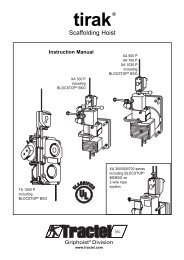
tirak ®<strong>Scaffolding</strong> <strong>Hoist</strong>AdditionalInstruction Manualfor TIRAK ® hoists with2 wire rope systemsXE 501 PXE 501 PAXE 500 PXE 701 PXE 700 PwithBLOCSTOP ®BS/BSOXE 301 PwithBLOCSTOP ®BS/BSONOTE:The following part of this manualonly contains instructions referring tothe 2 wire rope system.For all other instructions refer to pages2 to 20.21
TABLE OF CONTENTSofADDITIONAL INSTRUCTIONSA2. DESCRIPTIONA2.1 Two wire rope System ........................................... 22A2.2 Secondary Brake ................................................... 22A2.3 Wire Ropes ............................................................ 23A2.7 Technical Data ....................................................... 24A3. RIGGING INSTRUCTIONSA3.1 GeneralA3.1.1 Scope ......................................................... 25A3.1.2 Checks before rigging ............................... 25A4. WIRE ROPEA4.2 Wire Rope Rigging Instructions ............................ 26A4.3 Wire Rope Reeving ............................................... 27A4.4 De-rigging ............................................................... 29A5. OPERATING INSTRUCTIONSA5.1 General ................................................................... 29A5.3 Emergency Descent ............................................... 30A5.4 Secondary Brake Action ......................................... 31A6. TROUBLE SHOOTINGA6.4 BS/BSO Secondary Brake ..................................... 32A7. INSPECTIONS and MAINTENANCE ................. 32A7.1 InspectionsA7.1.1 Daily Inspections ........................................ 33A7.2 MaintenanceA7.2.1 TIRAK ® <strong>Hoist</strong> .............................................. 34A7.2.2 Wire Ropes ................................................ 34A7.2.3 BLOCSTOP ® BS/BSO Secondary Brake .. 34INTRODUCTION1. GENERAL WARNING(See pages 3 to 5)A2. DESCRIPTIONA2.1 Two wire rope SystemTIRAK ® hoists (A) with BLOCSTOP ® BS/BSO overspeedand slack wire rope locking device (E) – hereaftercalled BS/BSO secondary brake – are principallyused with two wire ropes (see Fig. 33):– The TIRAK ® hoist goes up and down the primarywire rope (P).– The BS/BSO secondary brake works on both theprimary wire rope (P) and the secondary wirerope (S) as described below.A2.2 Secondary BrakeIn case of accelerating overspeed the BLOCSTOP ® BS/BSO secondary brake stops the descent immediatelyon the primary wire rope (P).In case of slack primary wire rope or primary wire ropefailure BS/BSO secondary brake stops the descent byimmediately locking on the secondary wire rope (S).THE SECONDARY BRAKE MUST ALWAYS BE AT-TACHED AND USED.NOTE: IF for any reason a SECONDARY ROPE ISNOT RIGGED and used, the BS/BSO secondarybrake functions the same as a BSOsecondary brake, and THIS SECTION IS NOLONGER APPLICABLE.22
A2.3 Wire RopesCAUTION:It is mandatory that both the PRIMARYAND THE SECONDARY WIRE ROPEMEET THE MANUFACTURERSSPECIFICATIONS!For details see pages 7 and 11.Unless specificly specified in writing by the manufacturer,only this special TIRAK ® wire rope may be used.NOTE: The manufacturer declines all responsibilityfor machines used with a wire rope otherthan specified by them.Figure 33(P)(E)(S)(e3)(P)(E)(S)(e3)(A)(A)(P)(S)(s1)(P)(s1)(S)XE 301 Pwith BLOCSTOP ® BS/BSOXE 500/700 P serieswith BLOCSTOP ® BS/BSOAEPSTIRAK ® <strong>Hoist</strong>BLOCSTOP ® BS/BSOsecondary brakee1 Control levere2 EMERGENCY STOPon the BLOCSTOPe3 Release lever for slackwire rope locking devicePrimary wire ropeSecondary wire ropes1 Tensioning weight forsecondary wire rope(for more details see Fig. 2, page 6)For detailed info about– Motor and Primary Brake,– Gear Reducer,– Emergency Descent without power,and– Wire Rope Driving Mechanismsee page 6.23
YEMERGENCYEMERGENCA2.7 Technical DataFigure 34DimensionsXE 301 PwithBLOCSTOP ®BS/BSO 500abUPSTOPDOWNcabSTOPUPDOWNcXE 501 PXE 501 PAXE 500 PXE 701 PXE 700 PwithBLOCSTOP ®BS/BSO 500<strong>Hoist</strong> Model XE 301 P XE 501 P XE 501 PA XE 500 P XE 701 P XE 700 PRated load lbs 700 1,000 1,000 1,000 1,500 1,500kg 315 450 450 450 680 680Lifting speed ft/min 33 35 35 35 35 35m/min 10 11 11 11 11 11Weight (with BS/BSO) lbs 88 130 128 112 130 119kg 40 59 58 51 59 54Dimensions over alla in. 30.7 33.5 33.5 33.5 33.5 33.5mm 779 852 858 858 858 852b in. 11.3 12.9 12.5 12.1 12.5 12.5mm 286 328 318 308 318 318c in. 13.8 17.3 15.5 15.5 15.5 15.5mm 351 439 394 394 394 394Motor specificationselectrical motor3-phase 220 V/60 cycles kW – – – 1.1 – 1.5A – – – 4.5 – 6.1single phase:110 or 220 V/ 60 cycles kW 0.55 1.1 – – – –A 10.0/4.8 19.0/8.5 – – – –220 V/ 60 cycles kW – – 1.1 – 1.5 –A – – 8.5 – 12.0 –wire rope in. 5/16diameter mm 8.4wire rope classification/ 5 x 19, 4 x 26, or 5 x 26, with fiber core, or 6 x 19, (min. 17 wiresconstruction per strand),galvanized or black, lubricated, preformed, IPS or XIPSnominal diameter in./mm 5/16 in. / 8.4 mmmaximum allowed in. 0.319 to 0.331diameter tolerances mm 8.1 to 8.4minimum actual lbs 10,000breaking strength kN 44.524
A3. RIGGING INSTRUCTIONSFig. 35 Relevant Items (principle sketch)A3.1 GENERALA3.1.1 ScopeInstructions and advice of this part of the manualexclusively refer to the following items (see Fig. 35):– TIRAK ® scaffold hoistwith BLOCSTOP ® BS/BSO secondary brake;– PRIMARY and SECONDARY special TIRAK ®wire ropes.Fixing thewire rope to thesupport equipmentPRIMARYTIRAK ® wire ropeSECONDARYTIRAK ® wire ropeTIRAK ® withBLOCSTOP ®BS/BSOsecondary brakeTIE-BACKfor secondaryTIRAK ® wire ropeConnectingTIRAK ® andplatform systemTensioning weightfor secondaryTIRAK ® wire ropeA3.1.2 Checks before riggingIt is a qualified person’s responsibility to check the wholeinstallation to meet all safety requirements of:– OSHA regulations and federal, state, provincial orlocal safety regulations,– the proper instructions delivered by the manufacturersof the other pieces of equipment included in yoursuspended scaffold installation.Some pieces are:– Support equipment including tie-backs for both theequipment itself and the secondary wire rope;– platform system, work-cage, or bosun’s chair;– safety equipment;– barricade below the drop of the platform/workcage/bosun’schair.NOTE: This information is NOT to be considered asa complete checklist for your specific installation.It is only a sample list of some generalcomponents, which make part of a typical suspendedscaffold installation with a two wire ropesystem (Fig. 36).Fig. 36Secondary wire ropeTie-backSECONDARYTIRAK ®wire ropeTIRAK ®withBLOCSTOP ®BS/BSOSuspendedplatformsystemTypical suspended scaffold installationwith a two wire rope systemSupport equipmentTie-backPRIMARYTIRAK ®wire ropeSafety equipment,HorizontalLifelineSupportequipmentPowersupplycord3.2 Power Supply and <strong>Hoist</strong> Controland3.3 <strong>Hoist</strong> Mounting(see pages 9 to 10)Tensioning weightfor secondaryTIRAK ® wire ropeBarricade25
A4. Wire Rope4.1 Wire rope specification(see pages 7 and 11)A4.2 Wire rope rigging instructionsCAUTION:Be sure to use wire rope according tospecification (see pages 7, 11), with thediameter (d) (Fig. 37) marked on theTIRAK ® nameplate for both the PRI-MARY and the SECONDARY wirerope.Figure 37 Checking Wire Rope Diameter “d”d(1) RIG FROM TOP.You should have enough wire rope to reach to theground or other safe level with about five feet (1.5 m)extra for ensuring safety.CAUTION:Always unreel and reel the wire rope ina straight line (Fig. 38) to prevent kinks,which make it unusable for the hoist.Figure 38 Wire Rope HandlingCORRECTIncorrect(2) If the wire rope is not equipped with a swaged fittingas shown in Fig. 39, proceed as follows:– Install heavy duty thimble with a minimum of three(3) J-Type (Fist Grip) Clamps (Fig. 40).– Apply first clamp approximately 7" (18 cm) fromthimble. Tighten nuts moderately.– Attach second clamp as close to thimble as possible.Leave nuts loose.– Attach the third clamp half-way between first andsecond clamp, leaving the nuts loose. Take up wirerope slack.– Tighten nuts evenly on all clips (approx. 30 ft-lbs.torque) as specified by the clamp manufacturer.WARNINGS:a) Retighten after the wire rope isloaded for the first timeb) Inspect fastening periodically.In use, wire ropes will stretch and reduce indiameter.Retighten all “Fist Grip” nuts periodically.26Figure 39Wire Rope Terminationby Swaged FittingHeavy dutythimbleFerrule(Sleeve)Figure 40Wire Rope Terminationby Fist Grip ClampsHeavy duty thimbleFist Grip Clamp
YEMERGENC(3) Anchor the wire rope ends (Fig. 41) to a riggingdevice, which complies with all relevant safety requirements.Be sure to use compatible connectingdevices, e. g. a 1/2 in. anchor shackle or similarwith adequate strength and safety factor. Secure it.Distance (a) between the wire ropes:approx 1 1 / 2in. / 40 mm.CAUTION:Secondary wire rope anchoring mustbe connected to a tie back (Fig. 42).(4) Insure that the anchor points of the wire rope aredirectly above the position of the hoists (Fig. 17 onpage 12).Fig. 41 Wire Rope AnchoringaInstallationlevelFig. 42 (principle drawg.)Anchoringdevicemin. 1/2 in.anchorshacklesTie backSecondarywire ropeWARNING:Improper spacing is dangerous andcould cause failure of the supportsystem.(5) Check that wire rope tip is to be welded round(Fig. 18 on page 12).A4.3 Wire rope reevingNOTE: Ensure both wire ropes hang parallelfrom the suspension point.Fig. 44Primary Wire Rope Reeving(Principle drawing valid for all TIRAK ® seires)(e3)(A)Entrancewire rope(P)(e3)(e1)A4.3.1 Primary wire rope (P)(1) Open the BSO secondary brake by pushing downthe control lever (e1) until it locks (Fig. 43).Push and hold release lever (e3) in its vertical position(use brake release lever (c4) to ease theoperation) to ease insertion of primary wire rope.STOPUP(B)Fig. 43 Opening of BS/BSO secondary BrakeDOWN(c4)(e3)(e1) Closed(c4)(e1) OPENCAUTION:Check that wire rope exit (C) is notblocked in any manner.Exit wire ropeMust not be loaded!(C)(2) With gloved hands slide the rope through releaselever hole and push it through the BSO secondarybrake at (A) into the hoist rope inlet (B).Push it inside, and press UP button, until the wirerope reeves itself automatically and exits at (C) onthe other side (Fig. 44).d) Let the primary wire rope run through until it istensioned.Never load the wire rope exiting from (C), byapplying a weight to, or tensioning.27
YEMERGENCA4.3.2 Secondary wire rope (S)(1) BS/BSO secondary brake should be opened by theprimary wire rope under load. Otherwise push andhold release lever (e3) in its vertical position(Fig. 45).Figure 46Secondary Wire Rope ReevingTIRAK ®X-seriesFig. 45 Opening of BS/BSO secondary BrakeSecondarywire rope (S)(c4)(e3)(D)(2) Insert secondary wire rope at (D), on T-series intorope guiding device (E), and push through until it istensioned (Fig. 46).(3) Above ground level fix a tensioning weight (s1) ofapprox. 25 lbs. (10 kgs) to the lower end of thesecondary wire rope (Fig. 46).This weight will help to pull the secondary wire ropethrough the BS/BSO secondary brake and avoidslack wire rope above the hoist, which could bedangerous in the event of fall.(4) Take precautions to make sure tensioning weight(s1) will not damage property or create a hazardby swinging freely.STOPUPDOWNA4.3.3 Primary Wire Rope EndAfter primary wire rope reeving through the hoist,be sure to loop and clamp the free end of the wire ropeto prevent the rope from inadvertently unreeving throughthe hoist.Always tie this loop, using a fist grip clamp, when theplatform is at ground level (Fig. 47).Figure 47Loop at Free Primary Wire Rope EndBottom free end ofprimary wire ropeFistGripClamp(s1)WARNING:AT EVERY SET-UP OR RE-RIGGINGcheck the wire rope length to ensurethat it reaches the ground or othersafe level with about five feet (1.5 m)extra for safety.28
A4.4 De-RiggingA4.4.1 Secondary wire rope(1) Lower the platform until it almost reaches its safeand stable support. Leave the primary wire ropetensioned so that the release lever (e3) of BS/BSOsecondary brake is still upright.(2) Remove the tensioning weight (s1).(3) If release lever (e3) is not held in its open positionby the tensioned primary wire rope, hold it in itsopen position by using brake release lever (c4) accordingto Fig. 45 to ease operation.(4) With gloved hands pull out the secondary wire rope.A4.4.3 Wire Rope StorageClean the wire ropes, reel them (Fig. 48), and storethem in a clean and dry place.Figure 48 Wire Rope HandlingA4.4.2 Primary wire rope(1) Lower the platform to a safe and stable support untileach TIRAK ® hoist is unloaded.(2) Remove the loop at the free wire rope end.(3) Press DOWN button to let the wire rope run out.As soon as the suspension wire rope is not underload, hold release lever (e3) of BS/BSO secondarybrake in its open position by using brake releaselever (c4) according to Fig. 45 to ease operation.(4) With gloved hands slowly pull the primary wire ropethrough BS/BSO secondary brake.A5. Operating InstructionsA5.1 GENERAL(1) BE FAMILIAR with the equipment and its propercare.DO NOT operate hoist, if adjustment or repairs arenecessary, if any warning, operating or capacityinstructions normally attached to the hoist are obscured,damaged, or missing. (See labels’ list onpage 34).REPORT same promptly to your supervisor and alsonotify next operator, when changing shifts.(2) WARNING: SAFETY DEMANDSTHAT YOU TEST OUT THE SYSTEMBEFORE GOING ALOFT:Figure 49BS/BSO Secondary BrakeCheck ISlack primarywire ropee3Secondarywire ropea) CHECK PLATFORM fully rigged and loaded bycycling UP and DOWN several times near groundlevel or safe surface.b) CHECK PRIMARY BRAKE for mechanical function:When stopping the hoist the load must beheld immediately.c) CHECK BS/BSO SECONDARY BRAKE:IAt ground level push DOWN button to getslack primary wire rope – release lever (e3)tilts to the side to close BS/BSO secondarybrake for the secondary wire rope (Fig. 49).With gloved hands try to pull the secondarywire rope upwards: it must be impossible.29
c) CHECK BS/BSO SECONDARY BRAKE:(continued)II At ground level first close the BSO secondarybrake by pushing EMERGENCY STOP button(e2). Then push Control lever in DOWN-positionand make the wire rope form a loopbetween TIRAK ® casing and BSO secondarybrake (Fig. 50). Open BSO secondary brakeby pulling down control lever (e1) until it locksin the open position.Push release lever (e3) in its upright positionand with gloved hands sharply pull primarywire rope in arrow direction (Fig. 50) – theBS/BSO secondary brake should close immediately(Fig. 51).Reset BSO secondary brake by pushingdown control lever (e1) until it locks in theopen position.III Lift platform 3 ft. (1 m) above ground or safesurface, and push EMERGENCY STOP button(e2) of the BS/BSO secondary brake(Fig. 51).Lower the platform to check that the BS/BSOsecondary brake holds the load. A loop shouldform as shown in Fig. 50, which means theBS/BSO is supporting the load.Raise platform until the hoist supports the load.Reset (e1) to the open position.IV During operation regularly check through thewindow (e4) that the centrifugal weights arerotating (Fig. 50).WARNING: IF DURING ONE OF THECHECKS THE BS/BSO SECONDARYBRAKE MALFUNCTIONS, IT MUSTBE REPLACED.Figure 50BS/BSO SecondaryBrakeCheck II(e2) EMERGENCYSTOPFigure 51BS/BSO Secondary BrakeCheck III / IV(e2) EMERGENCYSTOP(e3)(e1) Closed(e1) OPENPrimary wirerope loop(Secondarywire rope)(e1) CLOSED(e1) Open(e4) Windowd) Check EMERGENCY STOP button and pushbuttoncontrol according to page 12.e) CONTINUOUSLY CHECK rigging, lines, clearances,and all other elements throughout theentire time on the job.5.2 Normal operation (see page 15)A5.3 Emergency DescentIn case of emergency you can descend with the platformwithout power proceeding as follows:(1) Take the brake release lever (A) from the carryinghandle, and insert it through the motor fan coverhole into the brake release bow. Lift in arrow direction(Fig. 52). The hoist begins to lower at moderatespeed, which is regulated by a mechanical centrifugalbrake.(2) To STOP just release the lever.(3) After use: restore brake release lever (A) into itsstorage position.30CAUTION:DO NOT USE EMERGENCY DESCENTAS REGLAR TECHNIQUE TO LOWER.Figure 52ABBrake ReleaseC
If during emergency descent the BS/BSO secondarybrake has been activated, it could be because:CASE (A): The BSO overspeed device has lockedon the primary rope.CASE (B): The BS slack wire rope device has lockedon the secondary wire rope.(Platform hits obstruction during descent)To unlock BS/BSO secondary brake proceed as follows:– Remove rubber cap (B) from motor fan cover,take hand wheel (C) from its support on the TIRAK ®casing, and place it on the motor shaft (Fig. 52).– With the brake opened (see above) turn the handwheel clockwise (T-series) resp. counter-clockwise(X-series) until the hoist supports the load.– CASE (A): Reset BSO overspeed device by pushingdown control lever (e1) until it locks in theopen position (Fig. 50).– CASE (B): The BS slack wire rope device is automaticallyopened by the transfer of the load tothe primary wire rope.– Restore hand wheel (C) into its storage position,and put back rubber cap (B) on the motor fancover.– Continue with manual descent.A5.4 BS/BSO Secondary Brake Action(1) EMERGENCY STOPPush EMERGENCY STOP button of the BS/BSOSecondary brake, if – for whatever reason – youwant to absolutely stop downward travel of the platform.(2) To reset BS/BSO secondary brake:Raise the platform until the hoist supports the load.Push the control lever in the OPEN position.DO NOT force it open.(3) If the BS/BSO secondary brake has automaticallyclosed on the primary wire rope, i. e. control lever(e1) has returned to CLOSED position (Fig. 51):GO UP UNTIL THE HOIST SUPPORTS THELOAD – the tensioned primary wire ropeautomatically re-opens the BS/BSO secondarybrake for the secondary wire rope to moveagain freely through the device.CLEAR THE OBSTRUCTION and descend.CAUTION: If the BS/BSO secondary brakerepeatedly stops downward travel, contactthe supplier for advice.CASE (A)WARNING: STOP DOWNWARD TRAVEL!YOU MAY HAVE RUN OFF THE PRI-MARY WIRE ROPE CAUSING OVER-SPEED. WITH EXTREME CAUTIONTRY TO GO UP.IF YOU CANNOT GO UP,A RESCUE IS REQUIRED.When the hoist supports the load,reset the BS/BSO secondary brakeas described above.Figure 53BS/BSOwith SlackPrimaryWire RopeSlack primarywire rope(e3)Secondarywire ropeCASE (B)WARNING:STOP DOWNWARD TRAVEL! THE PRI-MARY WIRE ROPE HAS FAILED.RESCUE IS REQUIRED.(4) If the BS/BSO secondary brake has automaticallyclosed on the secondary wire rope, i. e. releaselever (e3) is tilted because of slack primary wirerope (Fig. 53):WARNING: STOP DOWNWARD TRAVEL!THE PLATFORM HAS HIT AN OB-STRUCTION PREVENTING DOWN-WARD MOVEMENT.WARNING:DURING USE OF THE HOISTNEVER DETACH BS/BSOSECONDARY BRAKE!31
A6. TROUBLE SHOOTINGWARNINGS!Avoid injuries:1. Checks and repair of the electricequipment must only be carriedout by QUALIFIED ELECTRICIANS!Wiring diagrams are shown in the controlbox of the motor.2. DO NOT OPEN ANY CONTROL BOX OR PEN-DANT CONTROL WITH POWER SUPPLY TOHOIST!3. Any other repair should only be carried outby the supplier (TRACTEL Group Company)or by a qualified person, and only originalspare parts shall be used.6.1 Wire Rope Drive Mechanism Troubles6.2 Motor Troubles (see pages 16 to 17)6.3 Primary Brake TroublesA6.4 BS/BSO Secondary Brake TroublesProblem Cause Remedy1. <strong>Hoist</strong> goes up but not down BS/BSO secondary brake is closeda) Primary wire rope has run out a) WARNING: STOP DOWNWARD TRAVEL!or has failed. Proceed according para. A5.4, (3), page 30.b) Platform has hit an obstruction b) WARNING: STOP DOWNWARD TRAVEL!Go up until the hoist supports the load,and clear the obstruction.Details in para A5.4, (4), page 31.2. BS/BSO secondary brake a) Mechanical defect. a) Contact the supplier.automatically closeswithout apparent reason. b) Oversized or damaged wire rope b) Check wire rope and replace, if necessary.If you cannot find a trouble’s cause, contact the supplier.A7. INSPECTIONS and MAINTENANCENOTE: A maintenance program should start foreach hoist immediately after it is entered intoservice.This maintenance program should complywith recommendations in the applicable partsand Instruction Manual, and all pertinant Federal,State, Provincial and Local regulations.Regular inspections should be followed forthe life of the hoist and written inspectionrecords kept as specified.32
A7.1 InspectionsA7.1.1 DAILY INSPECTIONSEACH DAY PRIOR TO USE AND DURING OPERA-TION CHECK:(1) Primary brake function:“click” noise, when starting/stopping the hoist.(2) BLOCSTOP BS/BSO secondary brake function.IAt ground level or on a safe surface push DOWNbutton to get slack in the primary wire rope:release lever (e3) tilts to the side to closeBS/BSO secondary brake on the secondarywire rope (Fig. 54).With gloved hands try to pull the secondary wirerope upwards: it must be impossible.II At ground level first close the BSO secondarybrake by pushing emergency stop button (d2).Then push Control lever in DOWN-position andmake the wire rope form a loop between TIRAK ®casing and BSO secondary brake (Fig. 55). OpenBSO secondary brake by pulling down controllever (d1) until it locks in the open position.Push release lever (e3) in its upright positionand with gloved hands sharply pull wire rope inarrow direction (Fig. 54) – the BS/BSO secondarybrake should close immediately (Fig. 56).Reset BS/BSO secondary brake by pushingdown control lever (e1) until it locks in the openposition.III Lift platform 3 ft. (1 m) above ground or safesurface, and push EMERGENCY STOP button(e2) of the BS/BSO secondary brake (Fig. 56).Lower the platform to check that the BS/BSOsecondary brake holds the load. A loop shouldform as shown in Fig. 55, which means theBS/BSO is supporting the load.Raise platform until the hoist supports the load.Reset (e1) to the open position.IV During operation regularly check through thewindow (e4) that the centrifugal weights arerotating (Fig. 56).(3) Wire rope: free of kinks, cuts, broken wires, birdcages,heat damage, contamination etc.(4) Wire rope corrosion due to acid or caustics. Replacewire rope if exposed to these contaminants.(5) Wire rope lubrication: The wire rope has to beclean and lightly lubricated.(6) RiggingWire rope termination, connection to the suspensionsystem. It must be aligned and secure.(7) Check for parts damage.WARNING: If there is any:STOP working, unless the damagedpart(s) is (are) replaced.Figure 54BS/BSO SecondaryBrakeCheck ISlack primarywire ropeFigure 55BS/BSO SecondaryBrakeCheck II(e3)(e2) EMERGENCYSTOPFigure 56BS/BSO Secondary BrakeCheck III / IV(e2) EMERGENCYSTOPSecondarywire ropePrimarywire rope(e3)(e1) Closed(e1) OPENPrimary wirerope loop(Secondarywire rope)(e1) CLOSED(e1) Open(e4) Window(8) Safety harness(es), lifeline(s), fall arrester(s)and lanyard(s) must be used at all times in accordancewith the requirements of OSHA regulationsand state, provincial or local codes.33
YEMERGENC7.1.2 MONTHLY INSPECTIONS7.1.3 1/2-YEAR INSPECTION (see page 19)A7.2 MaintenanceA7.2.1 TIRAK ® <strong>Hoist</strong>(1) Daily check the primary and BS/BSO secondarybrake.(2) Daily check for visible part damage.(2) Keep wire rope clean and lightly lubricated toprevent abnormal wear of the wire rope drivingmechanism.A7.2.2 Wire Ropes(1) CAUTION:It is mandatory that both the PRI-MARY AND THE SECONDARYWIRE ROPE meet the manufacturersspecifications!For details see pages 7 and 11.This ensures the reliable function of the hoist.(2) To warrant maximum lifetime we recommend:– The wire rope must be unreeled andreeled in a straight line (Fig. 57).Figure 588. NAMEPLATES & LABELS8.1 Nameplates1 TIRAK ® nameplate2 Motor nameplate3 Primary brake nameplate4 BLOCSTOP ® Secondary brake nameplate8.2 Labels4a Advice label (additional secondary brake check)5 Warning label (wire rope jam)6 Advice label (secondary brake operation)7 General Warning & Advice label8 Emergency Descent label9 Wire rope diameter label10 UL classification labelNOTE: If any nameplate or label is missingor obscured, contact the supplier forreplacement nameplates/labels.Nameplates and Labels4aFigure 57Wire Rope HandlingTIRAK ®X-series485109STOP6UPCORRECT123DOWN7– Keep wire ropes clean.– Lubricate wire ropes regularly with a ragsoaked with oil.– Never let the wire ropes rub against sharpedges.– Always see that the wire rope outlet is notobstructed.– Let the free wire rope ends untwist to preventwire rope from making loops.– If the wire rope changes direction it shouldbe guided by sheaves or rollers to avoiddamage.9104571TIRAK ®T-series2386A7.2.3 BLOCSTOP ® BS/BSO Secondary BrakeBesides the daily checks, keep all wire rope cleanand lightly lubricated.34
1®tirak Model XE 501Made in GermanyUS.Patents No. 3,965,767 / 4,193,311 / 4,345,741 / 4,706,940.Other US. Patents pending.Rated load: 1,000 lbs 450 kgsTravel speed: 35 ft/min 11 m/minOperating voltage: Current consumption:110/220 VAC 19.5/9.5 APower-supply cord: #10, Type STO, 600 VAC.Maximum length: 250 ft. at 110 VAC,750 ft. at 220 VAC.Do not let the voltage at motor terminals dropbelow motor nameplate rating under load.Serial No.:Year of manufacture:00000 2001 / AWire rope diameter: 5/16 in. 8.4 mmWire rope classification/construction:5x19, 4x26, or 5x26 with fiber core,or 6x19, (min. 17 wires per strand),galvanized or black, lubricated,preformed, IPS or XIPS.G 441-03/01Supplier’s addressPPrinted in Germany4BLOCSTOP ®secondary brakeModel Serial numberBSORated load Wire rope Ø Year of manuf.kg mmlbs. in.CHECKING1) Before going aloft, daily check as follows:– At ground level push DOWN buttonand allow the wire rope to form abow between TIRAK ® casing andBSO secondary brake.With gloved hands sharply pullwire rope upwards – the BSOsecondary brake should closeimmediately.– Lift platform 3 ft. (1 m) aboveground or safe surface, and pushEMERGENCY STOP button of theBSO secondary brake.Lower the platform to check thatthe BSO secondary brake holdsthe load.Raise platform until the hoistsupports the load. Reset BSOsecondary bake by pushing downcontrol lever until it locks.2) During operation centrifugal weightsmust rotate.Check regularly through the window.WARNING: If during the above checksthe BLOCSTOP malfunctions, replace itand return to the supplier for inspection.Address see TIRAK nameplate.2GREIFZUG GmbH Bergisch GladbachMade in Germany3TypeNr.E-Mot. 60 Hz U minkWcos ϕVASchalt. Schutzart IP 55 F Is.Kl.GREIFZUG GmbH Bergisch GladbachBremstyp4aADDITIONAL CHECKINGAt ground level push DOWN button toget slack primary wire rope – releaselever tilts to the side to close BS/BSOsecondary brake for the secondary wirerope.With gloved hands try to pull the secondarywire rope upwards: it must beimpossible.Leistung W Spulenspannung VMomentNm5If the motor energizes but the wire ropedoes not move through the hoist:STOP THE HOIST IMMEDIATELY!Damaged wire rope may be jammed inside the hoist.Any attempt to move the hoist up or down could causea dangerous situation and result in bodily injury.6NOTICE:This hoist is equipped with a controlleddescent device that will automaticallyengage in case of primary brake failure.Descent can be stopped with manualoperation of the secondary brake.35
7WARNING:Only authorized,properly trained, andphysically fit personnel shalloperate this hoist in strict accordancewith the instructions onthe hoist and applicable codes!Copy of instructions must be keptwith the hoist.OperatingWARNING:Immediately STOP RUNNINGTHE HOIST, if wire rope doesnot move through.EMERGENCY DESCENT:Take brake release lever out ofTIRAK ® handle, and insert inmotor cover hole. Push leverupwards.To STOP release lever.CAUTION: The TIRAK ®can only be used in conjunctionwith the BLOCSTOP OVER-SPEED device, which is anintegral part of the equipment.Use of this equipment is unsafeand unlawful without proper fallprotection equipment used in accordancewith OSHA requirements.SET-UP INSTRUCTIONS: Anchorthe hoist, and connect toelectric supply. Red button mustbe out to start the motor.Start motor, and introduce wirerope, until it reeves itself automatically.Ensure free rope exit.Use only specified wire ropein good condition with short taperedend! Daily check for brokenwires and kinks.For spare parts or in case of inquiryplease mentionMachine Type and Serial No.!G442-03/01Printed in Germany8 Notablaß9 Wire rope Wire ropeBremslüfterhebelim HandgriffØØEmergency DescentBrake release leverin TIRAK handleDescente d’urgenceManette de commande du frein5/16”On TIRAK ® 3/8”On TIRAK ®G 207-09/94 dans la poignée de portageXE 300 P-series,XE 500/700 P-seriesXE 720/721 PXE 1020 PTE 1020 P10AS TO LOAD CAPACITY(ELECTRICAL FIRE AND SHOCK HAZARDS)*ONLY.* Applies to electric winches. G 212-10/0136
9. WARRANTY INFORMATION(1) TRACTEL INC. warrants its equipment to befree from defects in material and workmanshipunder normal use and service.(2) Our obligation under this warranty is limited torepairing or replacing, at our option, any part ofthe unit, which proves examination to our satisfactionto be defective in material orworkmanship, if the item in question is returnedthrough a TRACTEL INC. distributor, transportationprepaid, within one (1) year from theequipment is sold to the original purchaser 1) .Return shipment must be prepaid.(3) Any parts proved to be defective upon our inspectionwill be repaired or replaced at no costfor the parts themselves.(4) The obligation under this warranty does notinclude labor or travelling costs, or consequentialdamages of any kind.(5) Any defect in this equipment must immediatelybe brought to attention of the distributor fromwhom the unit was purchased. The distributorwill make arrangements with the factory for repairsor replacement of parts within the terms ofthis warranty.(6) TRACTEL INC.’s obligation is limited to replacingparts and does not include replacing thecomplete unit. This warranty is void on any unitthat has been modified or tampered with, repairedby persons other than a factoryrepresentative or an authorized TRACTEL INC.distributor, repaired with other than TRACTELINC. standard parts, or damaged by reasons ofaccident, alteration, misuse, or abuse.(7) This warranty is in lieu of all other warranties,expressed or implied. We do not authorize anyperson or representative to make other guaranteeor to assume for us any liability in connectionwith the sale of our appliances other than thosecontained herein. Any agreement outside of orcontradictory to the foregoing shall be void andof no effect.1) “Original purchaser” definition:for rental machines: Dealer,for resale machines: First user.10. ADDITIONAL SOURCES AND TRAININGThe Scaffold Industry Association Inc.offers a certificated training course for suspended scaffold users.Information may be obtained fromScaffold Industry Association Inc.20335 Ventura Blvd. Suite 310Woodlands Hills, California 91364Telephone: (818) 610-03 20Fax: (818) 610-03 23www.scaffold.orge-mail: sia@scaffold.org37
GIVE TO SCAFFOLD ERECTOR & USER OR POST ON JOBCODE OF SAFE PRACTICES FORSUSPENDED POWERED SCAFFOLDSIt shall be the responsibility of all employers and users to read and comply with the following common senseguidelines, which are designed to promote safety in the erection and use of suspended powered scaffolds.These guidelines do not purport to be all-inclusive nor to supplant or replace other additional safety and precautionarymeasures to cover usual or unusual conditions.If these guidelines conflict in any way with any state, local or federal statute or governmental regulation,said statute or regulation shall supersede these guidelines. It is the responsibility of each user tocomply with these guidelines.I. GENERAL GUIDELINESA. POST THESE SAFETY GUIDELINES in a conspicuousplace and be sure that all persons who erect, use, locate,or dismantle suspended scaffold systems are fully awareof them.B. FOLLOW ALL EQUIPMENT MANUFACTURERS’RECOMMENDATIONS as well as all state, local andfederal codes, ordinances and regulations relating tosuspended powered scaffolding.C. SURVEY THE JOBSITE.A survey shall be made of the jobsite for hazards such asexposed electrical wires, obstructions that could overloador tip the suspended powered scaffold when it is raised orlowered, unguarded roof edges or openings, inadequateor missing tiebacks.Those conditions should be corrected before installing orusing suspended powered scaffold systems.D. INSPECT ALL EQUIPMENT BEFORE EACH USE.Never use any equipment that is damaged or defectivein any way. Tag damaged or defective equipment andremove it from the jobsite.E. ERECT AND DISMANTLE SUSPENDED POWEREDSCAFFOLD EQUIPMENT in accordance with design and/or manufacturer’s recommendations.F. DO NOT ERECT, DISMANTLE, OR ALTER SUSPENDEDPOWERED SCAFFOLD SYSTEMS unless under the supervisionof a competent person.G. DO NOT ABUSE OR MISUSE SUSPENDED POWEREDSCAFFOLD EQUIPMENT.Never overload platforms or hoists.H. ERECTED SUSPENDED POWERED SCAFFOLDSSHOULD BE CONTINUOUSLY INSPECTED by the userto ensure that they are maintained in a safe condition.Report any unsafe condition to your supervisor.I. NEVER TAKE CHANCES! IF IN DOUBT REGARDINGTHE SAFETY OR USE OF SUSPENDED SCAFFOLDS,CONSULT YOUR SCAFFOLD SUPPLIER.J. NEVER USE SUSPENDED SCAFFOLDS EQUIPMENTFOR PURPOSES OR IN WAYS FOR WHICH IT WASNOT INTENDED.K. CARE SHOULD BE TAKEN WHEN OPERATING ANDSTORING EQUIPMENT DURING WINDY CONDITIONS.L. SUSPENDED POWERED SCAFFOLD SYSTEMS shouldbe installed and used in accordance with the manufacturer’srecommended procedures.Do not alter components in the field.M. SUSPENDED POWERED PLATFORMS MUST NEVERBE OPERATED NEAR LIVE POWER LINES, unlessproper precautions are taken.Consult the power service company for advice.N. ALWAYS ATTACH FALL ARREST EQUIPMENT whenworking on suspended powered scaffolds.O. DO NOT WORK ON OR INSTALL SUSPENDEDPOWERED SCAFFOLDS if your physical condition issuch that you feel dizzy, or unsteady in any way.P. DO NOT WORK ON SUSPENDED POWERED SCAF-FOLDS when under influence of alcohol or illegal drugs.II. GUIDELINES FOR ERECTION AND USE OF SUS-PENDED SCAFFOLD SYSTEMS.A. RIGGING:1. WEAR FALL PREVENTION EQUIPMENT when riggingon exposed roofs or floors.2. ROOF HOOKS, PARAPET CLAMPS, OUTRIGGERBEAMS, OR OTHER SUPPORTING DEVICES must becapable of supporting the hoist machine rated load with afactor of safety of 4.3. VERIFY THAT THE BUILDING OR STRUCTURE WILLSUPPORT the suspended loads with a factor of safetyof 4.4. ALL OVERHEAD RIGGING must be secured from movementin any direction.5. COUNTERWEIGHTS USED WITH OUTRIGGER BEAMSmust be of a non-flowable material and must be securedto the beam to prevent accidental displacement.6. OUTRIGGER BEAMS THAT DO NOT USE COUNTER-WEIGHTS must be installed and secured on the roofstructure with devices specifically designed for that purpose.Direct connections shall be evaluated by a competentperson.7. TIE BACK ALL TRANSPORTABLE RIGGING DEVICES.Tiebacks shall be equivalent in strength to suspensionropes.8. INSTALL TIEBACKS AT RIGHT ANGLES TO THE FACEOF THE BUILDING and secure, without slack, to a structurallysound portion of the structure, capable of supportingthe hoisting machine rated load with a safetyfactor of 4.IN THE EVENT TIEBACKS CANNOT BE INSTALLEDAT RIGHT ANGLES, two tiebacks at opposing anglesmust be used to prevent movement.9. RIG AND USE HOISTING MACHINES DIRECTLYUNDER THEIR SUSPENSION POINTS.38
B. WIRE ROPE AND HARDWARE:1. USE ONLY WIRE ROPE AND ATTACHMENTS asspecified by the hoisting machine manufacturer.2. ASSURE THAT WIRE ROPE IS LONG ENOUGH toreach to the lowest possible landing.3. CLEAN AND LUBRICATE WIRE ROPE in accordancewith the wire rope manufacturer’s instructions.4. HANDLE WIRE ROPE WITH CARE.5. COIL AND UNCOIL WIRE ROPE in accordance with thewire rope manufacturer’s instructions in order to avoidkinks or damage.6. TIGHTEN WIRE ROPE CLAMPS in accordance with theclamp manufacturer’s instructions.7. DO NOT USE WIRE ROPE THAT IS KINKED, BIRD-CAGED, CORRODED, UNDERSIZED, OR DAMAGED INANY WAY. Do not expose wire rope fire, undue heat,corrosive atmospheres, electricity, chemicals, or damageby tool handling.8. USE THIMBLES AND SHACKLES AT ALL WIREROPE SUSPENSION TERMINATIONS.9. USE J-TYPE CLAMPS OR SWEDGE FITTINGS.Do not use U-bolts.Retighten J-Clamps under load and retighten daily.10. WIRE ROPES USED WITH TRACTION HOISTS MUSTHAVE PREPARED ENDS. Follow manufacturer’srecommendations.C. POWER SUPPLY:1. GROUND ALL ELECTRICAL POWER SOURCESAND POWER CORD CONNECTIONS and protect themwith circuit breakers.2. USE POWER CORDS OF THE PROPER WIRE SIZETHAT ARE LONG ENOUGH for the job.3. POWER CORD CONNECTIONS MUST BE RESTRAINEDto prevent their separation.4. USE STRAIN RELIEF DEVICES TO ATTACH POWERCORDS TO THE SUSPENDED SCAFFOLD to preventthem from falling.5. PROTECT POWER CORDS AT SHARP EDGES.6. USE GFI WITH POWER TOOLS.D. FALL ARREST EQUIPMENT:1. EACH PERSON ON A SUSPENDED POWEREDSCAFFOLD must be attached to a separate fall arrestsystem unless the installation was specifically designednot to require one.2. EACH LIFELINE MUST BE FASTENED to a separateanchorage capable of holding a minimum of 5000 pounds.3. DO NOT WRAP LIFELINES AROUND STRUCTURALMEMBERS unless lifelines are protected and a suitableanchorage connection is used.4. PROTECT LIFELINES AT SHARP CORNERS to preventchafing.5. RIG FALL ARREST SYSTEMS to prevent free fall inexcess of six feet.6. SUSPEND LIFELINES FREELY without contact withstructural members or building facade.7. USE LIFELINES OF SIZE AND CONSTRUCTION thatare compatible with the rope grab used.8. ASSURE A PROPERLY ATTACHED ROPE GRAB ISINSTALLED ON EACH LIFELINE. Install in accordancewith the manufacturer’s recommendations.9. KEEP FALL ARREST DEVICE POSITIONED ABOVEYOUR HEAD LEVEL.10. USE ONLY FULL BODY HARNESSES of the proper sizeand that are tightly fastened.11. ASSURE FULL BODY HARNESS HAS LANYARDattachment with D-ring at the center of your back.12. CONSULT FALL PROTECTION SUPPLIER FORINSPECTION PROCEDURE. INSPECT FALL PROTEC-TION ANCHORAGE EQUIPMENT BEFORE EACH USE.13. WHEN A SECONDARY WIRE ROPE SYSTEM IS USED,a horizontal lifeline secured to two or more structuralmembers of the scaffold may be used in lieu of verticallifelines.E. DURING USE:1. USE ALL EQUIPMENT AND ALL DEVICES in accordancewith the manufacturer’s instructions.2. DO NOT OVERLOAD, MODIFY, OR SUBSTlTUTEEQUIPMENT.3. BEFORE COMMENCING WORK OPERATIONS preloadwire rope and equipment with the maximum working load,then retighten wire rope rigging clamps and check riggingto manufacturer’s recommendations.4. INSPECT ALL RIGGING EQUIPMENT AND SUSPEND-ED POWERED SCAFFOLDS SYSTEMS DAILY.5. INSPECT WIRE ROPE DURING EACH ASCENT ORDESCENT FOR DAMAGE.6. USE CARE TO PREVENT DAMAGE TO EQUIPMENTby corrosive or other damaging substances.7. CLEAN AND SERVICE EQUIPMENT REGULARLY.8. ALWAYS MAINTAIN AT LEAST FOUR (4) WRAPS OFWIRE ROPE ON DRUM TYPE HOISTS.9. DO NOT JOIN PLATFORMS unless the installationwas designed for that purpose.10. ONLY MOVE SUSPENDED SCAFFOLDS HORIZONTAL-LY WHEN NOT OCCUPIED.11. WHEN RIGGING FOR ANOTHER DROP assuresufficient wire rope is available before moving the suspendedscaffold system horizontally.12. WHEN WELDING FROM SUSPENDED POWERED SCAF-FOLDS:a. Assure platform is grounded to structure.b. Insulate wire rope above and below the platform.c. Insulate wire rope at suspension point and assure wirerope does not contact structure along its entire length.d. Prevent the bitter end from touching the ground.These safety guidelines set forth some common sense procedures for safely erecting, dismantling and using suspendedpowered scaffolding equipment. However, equipment and scaffolding systems differ, and accordingly, reference must alwaysbe made to the instructions and procedures of the supplier and/or manufacturer of the equipment.Since field conditions vary, and are beyond the control of the <strong>Scaffolding</strong>, Shoring and Forming Institute and Scaffold IndustryAssociation, safe and proper use of scaffolding is the sole responsibility of the user.Scaffold Industry Association Inc. & <strong>Scaffolding</strong>, Shoring and Forming Institute Inc., February 199839
More informationabout access equipment…DELTA ® outriggerModular platformsBeam clampsTIRAK ®air hoistsWorkcagesElectrical Accessories:– Power cords– Power yokes– Booster transformer– Insulated thimbles:TIRAK ®XE 2000 PInsulationbushingWire ropesin any length4,400 lbs.ratedcapacityBosun’s chairFALLSTOP ®Personalfall arrestsystemsGRIPHOIST ® manual hoistsSCAFOR ® manual hoist… on request!G 430.1-10/01 Printed in Germany © TRACTEL Inc. 2001Inc.Inc.40Griphoist ® Division110 Shawmut Road, P.O. Box 188CANTON, MA. 02021Tel.: (781) 401-3288Fax: (781) 828-3642e-mail: griphoist@worldnet.att.netGriphoist ® Division315 Cloverleaf Dr., Unit EBALDWIN PARK, CA. 91706Tel.: (626) 937-6727Fax: (626) 937-6730


