Finite Element Modeling with ANSYS - ETH
Finite Element Modeling with ANSYS - ETH
Finite Element Modeling with ANSYS - ETH
- No tags were found...

You also want an ePaper? Increase the reach of your titles
YUMPU automatically turns print PDFs into web optimized ePapers that Google loves.
<strong>Finite</strong> <strong>Element</strong> <strong>Modeling</strong> <strong>with</strong> <strong>ANSYS</strong>StrukturlaborSpring Semester 2010Tommaso DelperoGrégoire LepoittevinAlberto Sanchezwww.structures.ethz.chCENTRE OF STRUCTURE TECHNOLOGIESFull Name01.03.2011, page 1
Contents• What is the <strong>Finite</strong> <strong>Element</strong> Method?• <strong>Modeling</strong> <strong>with</strong> <strong>ANSYS</strong>- <strong>Element</strong> type- Modelling of composite materials- Boundary conditions and load introduction- Analysiswww.structures.ethz.chCENTRE OF STRUCTURE TECHNOLOGIESFull Name01.03.2011, page 2
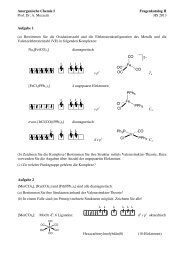
What is the <strong>Finite</strong> <strong>Element</strong> Method?• For many engineering problems analytical solutions are not suitable because of thecomplexity of the material properties, the boundary conditions and the structureitself.• The basis of the finite element method is the representation of a body or a structureby an assemblage of subdivisions called finite elements.• The <strong>Finite</strong> <strong>Element</strong> Method translates partial differential equation problems into aset of linear algebraic equations.Stiffness matrixK qFNodal vector forceNodal displacement vectorReference: Introduction to the finite element method, C. S. Desai and J. F. Abel, Van Nostrand ReinholdCompany, New York, 1972.www.structures.ethz.chCENTRE OF STRUCTURE TECHNOLOGIESFull Name01.03.2011, page 3
Contents• What is the <strong>Finite</strong> <strong>Element</strong> Method?• <strong>Modeling</strong> <strong>with</strong> <strong>ANSYS</strong>• <strong>Element</strong> type• Modelling of composite materials• Boundary conditions and load introductionwww.structures.ethz.chCENTRE OF STRUCTURE TECHNOLOGIESFull Name01.03.2011, page 4
<strong>Modeling</strong> <strong>with</strong> <strong>ANSYS</strong>• The modeling procedure is the following:GEOMETRYELEMENT TYPEShell or solid?MATERIAL PROPERTIESIsotropic or anisotropic material?MESH DEFINITIONIncluding the load introductionBOUNDARY CONDITIONSANALYSISStatic – Buckling analysisPOST PROCESSINGwww.structures.ethz.chCENTRE OF STRUCTURE TECHNOLOGIESFull Name01.03.2011, page 5
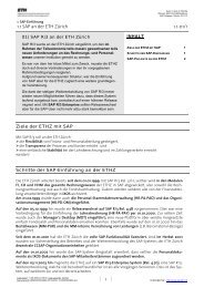
<strong>Modeling</strong> <strong>with</strong> <strong>ANSYS</strong> – Geometry and <strong>Element</strong> type• The geometry and the element type have to be considered together.• Shell element are typically used for structure where the thickness is negligiblecompared to its length and width• Nevertheless, a plate modeled <strong>with</strong> solid element would provide similar results. Thedisadvantage lies in the computation time.• Ansys provides a large choices of elements.Shell181 Shell281 Solid186www.structures.ethz.chCENTRE OF STRUCTURE TECHNOLOGIESFull Name01.03.2011, page 6
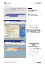
<strong>Modeling</strong> <strong>with</strong> <strong>ANSYS</strong> – Geometry and <strong>Element</strong> type• The Ansys command to define the element type is:• The geometry is defined <strong>with</strong> key points that are connect together to obtain either anarea or a volume.4:(0,0.5,0)1:(0,0,0)3:(1,0.5,0)2:(1,0,0)www.structures.ethz.chCENTRE OF STRUCTURE TECHNOLOGIESFull Name01.03.2011, page 7
<strong>Modeling</strong> <strong>with</strong> <strong>ANSYS</strong> – Material properties• Isotropic material like aluminum• Fiber reinforced material1. Determination of the engineering constants (Using C.A.P.)2. Implementation in Ansyswww.structures.ethz.chCENTRE OF STRUCTURE TECHNOLOGIESFull Name01.03.2011, page 8
<strong>Modeling</strong> <strong>with</strong> <strong>ANSYS</strong> – Mesh definition• Before meshing, it is necessary1. To select the geometry to mesh2. To give a material type3. To give an element type4. To select the mesh typeFree or mapped meshing5. To define the mesh refinementwww.structures.ethz.chCENTRE OF STRUCTURE TECHNOLOGIESFull Name01.03.2011, page 9
<strong>Modeling</strong> <strong>with</strong> <strong>ANSYS</strong> – Boundary Conditions (1)• Displacements constraintsnsel,s,loc,x,50-1,50+1nsel,r,loc,y,-1,1cm,support1,nodensel,s,loc,x,550-1,550+1nsel,r,loc,y,-1,1cm,support2,nodecmsel,s,support1,nodecmsel,a,support2,nodeD,all, , , , , ,uy, , , , ,Select „support“ nodesand create componentsSelect components andfix vertical displacementcmsel,s,support1,nodensel,r,loc,z,-1,1D,all, , , , , ,ux,uy,uz, , ,cmsel,s,support1,nodensel,r,loc,z,b-1,b+1D,all, , , , , ,ux,uy, , ,Select other nodes andfix displacements to geta staticallydeterminate structurewww.structures.ethz.chCENTRE OF STRUCTURE TECHNOLOGIESFull Name01.03.2011, page 10
<strong>Modeling</strong> <strong>with</strong> <strong>ANSYS</strong> – Boundary Conditions (2)• Loads introduction:The load is introduced into the structure by a “rigid” cylinder, that contributes todistribute the stresses. How can we model this effect?Simple line load<strong>Modeling</strong> the cylinderand the contactwww.structures.ethz.chCENTRE OF STRUCTURE TECHNOLOGIESFull Name3/1/2011, page 11
<strong>Modeling</strong> <strong>with</strong> <strong>ANSYS</strong> – Boundary Conditions (3)Simple line load<strong>Modeling</strong> the cylinder and the contactnsel,s,loc,x,l/2-1,l/2+1nsel,r,loc,y,h-1,h+1cm,mid,nodecp,next,all,mid*get,nodes_num,node,0,countF,all,Fy,-10000/nodes_numSelect nodes and createcomponent „mid“Create rigid element betweenthe nodes (Couple DOF)Apply a force on each node! Target element type: rigid cylinderET,11,Targe170! Contact element type: deformable elementsET,12,Conta174! Setting contact optionsKEYOPT,12,4,2KEYOPT,12,5,1KEYOPT,12,9,1KEYOPT,12,10,2KEYOPT,12,11,1KEYOPT,12,12,0KEYOPT,12,2,0KEYOPT,11,1,0KEYOPT,11,2,1KEYOPT,11,3,0KEYOPT,11,5,0! Real Constantradius = 15R,20,radius,radius,1.0,0.1,0, !Real ConstantsReal,20RMORE,,,1.0E20,0.0,1.0,RMORE,0.0,0,1.0,,1.0,0.5RMORE,0,1.0,1.0,0.0,,1.0! Contact material, friction coefficientMP,MU,13,0.01Mat,13! Mesh deformable contact elementsasel,s,area,,4nslalsel,s,line,,3,7,4nsll,ansel,r,loc,x,l/2-15,l/2+15Real,20Type,12Esurf! Create rigid target elementN,100000,l/2,h+radius+.1,-b/2N,100001,l/2,h+radius+.1,1.5*bN,100002,l/2,h+radius+.1,b/2Real,20Type,11TSHAP,CYLIE,100000,100001TSHAP,PILOE,100002! Reverse normal vectorESEL,S,TYPE,,12ESEL,R,REAL,,20ESURF,,REVERSE!Loadsnsel,s,node,,100002f,all,fy,-10000www.structures.ethz.chCENTRE OF STRUCTURE TECHNOLOGIESFull Name01.03.2011, page 12
<strong>Modeling</strong> <strong>with</strong> <strong>ANSYS</strong> – Boundary Conditions (3)Simple line load<strong>Modeling</strong> the cylinder and the contactCPU Time8.3 sCPU Time45.4 s„Rigid element“ Displ-1.01 mm„Cylinder“ Displ-1.07 mmMax Von Mises stress150.1 MPaMax Von Mises stress141.3 MPawww.structures.ethz.chCENTRE OF STRUCTURE TECHNOLOGIESFull Name01.03.2011, page 13
<strong>Modeling</strong> <strong>with</strong> <strong>ANSYS</strong> – Analysis• Static Analysis • Buckling analysiswww.structures.ethz.chCENTRE OF STRUCTURE TECHNOLOGIESFull Name01.03.2011, page 14
Thank you foryour attention.www.structures.ethz.chCENTRE OF STRUCTURE TECHNOLOGIESFull Name01.03.2011, page 15