Ref. 1043/231 â 1043/232 Mod. 1043 - DOMUSWIRE
Ref. 1043/231 â 1043/232 Mod. 1043 - DOMUSWIRE
Ref. 1043/231 â 1043/232 Mod. 1043 - DOMUSWIRE
- No tags were found...

You also want an ePaper? Increase the reach of your titles
YUMPU automatically turns print PDFs into web optimized ePapers that Google loves.
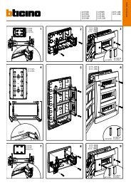
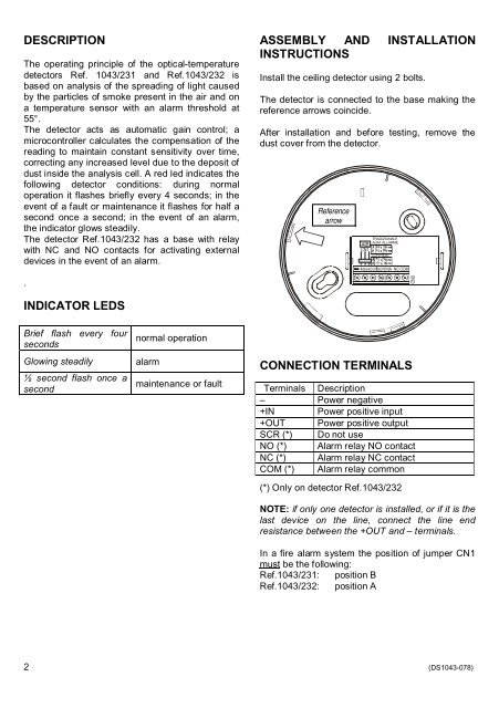
DESCRIPTIONThe operating principle of the optical-temperaturedetectors <strong>Ref</strong>. <strong>1043</strong>/<strong>231</strong> and <strong>Ref</strong>.<strong>1043</strong>/<strong>232</strong> isbased on analysis of the spreading of light causedby the particles of smoke present in the air and ona temperature sensor with an alarm threshold at55°.The detector acts as automatic gain control; amicrocontroller calculates the compensation of thereading to maintain constant sensitivity over time,correcting any increased level due to the deposit ofdust inside the analysis cell. A red led indicates thefollowing detector conditions: during normaloperation it flashes briefly every 4 seconds; in theevent of a fault or maintenance it flashes for half asecond once a second; in the event of an alarm,the indicator glows steadily.The detector <strong>Ref</strong>.<strong>1043</strong>/<strong>232</strong> has a base with relaywith NC and NO contacts for activating externaldevices in the event of an alarm..ASSEMBLY AND INSTALLATIONINSTRUCTIONSInstall the ceiling detector using 2 bolts.The detector is connected to the base making thereference arrows coincide.After installation and before testing, remove thedust cover from the detector.<strong>Ref</strong>erencearrowTRADIZIONALEALIM. ALLARMEABCN1CON RELEINOUTSCRNA NC COMCN2INDICATOR LEDSBrief flash every foursecondsGlowing steadily½ second flash once asecondnormal operationalarmmaintenance or faultCONNECTION TERMINALSTerminals Description– Power negative+IN Power positive input+OUT Power positive outputSCR (*) Do not useNO (*) Alarm relay NO contactNC (*) Alarm relay NC contactCOM (*) Alarm relay common(*) Only on detector <strong>Ref</strong>.<strong>1043</strong>/<strong>232</strong>NOTE: if only one detector is installed, or if it is thelast device on the line, connect the line endresistance between the +OUT and terminals.In a fire alarm system the position of jumper CN1must be the following:<strong>Ref</strong>.<strong>1043</strong>/<strong>231</strong>: position B<strong>Ref</strong>.<strong>1043</strong>/<strong>232</strong>: position A2 (DS<strong>1043</strong>-078)