Pre- Insulated Diamond Grip (PIDG*) Terminals ... - Soemtron.org
Pre- Insulated Diamond Grip (PIDG*) Terminals ... - Soemtron.org
Pre- Insulated Diamond Grip (PIDG*) Terminals ... - Soemtron.org
- No tags were found...

Create successful ePaper yourself
Turn your PDF publications into a flip-book with our unique Google optimized e-Paper software.
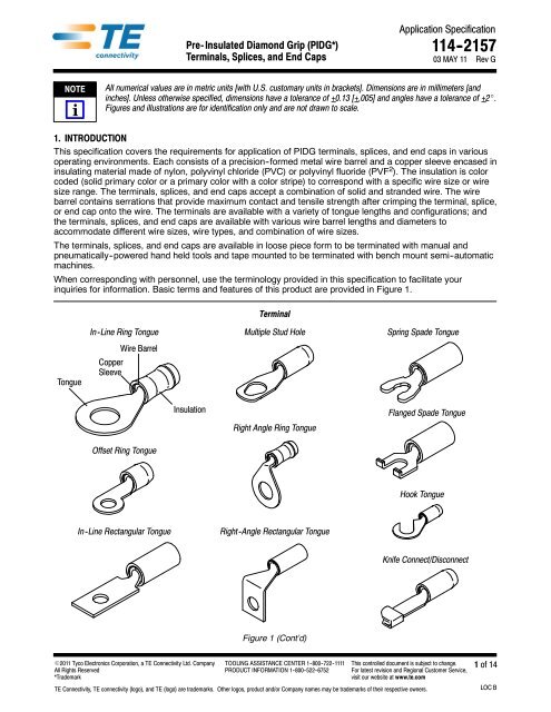
Application Specification<strong>Pre</strong>- <strong>Insulated</strong> <strong>Diamond</strong> <strong>Grip</strong> (<strong>PIDG*</strong>) 114 -2157<strong>Terminals</strong>, Splices, and End Caps 03 MAY 11 Rev GNOTEiAll numerical values are in metric units [with U.S. customary units in brackets]. Dimensions are in millimeters [andinches]. Unless otherwise specified, dimensions have a tolerance of +0.13 [+.005] and angles have a tolerance of +2_.Figures and illustrations are for identification only and are not drawn to scale.1. INTRODUCTIONThis specification covers the requirements for application of PIDG terminals, splices, and end caps in variousoperating environments. Each consists of a precision--formed metal wire barrel and a copper sleeve encased ininsulating material made of nylon, polyvinyl chloride (PVC) or polyvinyl fluoride (PVF 2 ). The insulation is colorcoded (solid primary color or a primary color with a color stripe) to correspond with a specific wire size or wiresize range. The terminals, splices, and end caps accept a combination of solid and stranded wire. The wirebarrel contains serrations that provide maximum contact and tensile strength after crimping the terminal, splice,or end cap onto the wire. The terminals are available with a variety of tongue lengths and configurations; andthe terminals, splices, and end caps are available with various wire barrel lengths and diameters toaccommodate different wire sizes, wire types, and combination of wire sizes.The terminals, splices, and end caps are available in loose piece form to be terminated with manual andpneumatically--powered hand held tools and tape mounted to be terminated with bench mount semi--automaticmachines.When corresponding with personnel, use the terminology provided in this specification to facilitate yourinquiries for information. Basic terms and features of this product are provided in Figure 1.TerminalTongueIn -Line Ring TongueCopperSleeveWire BarrelMultiple Stud HoleSpring Spade TongueInsulationRight Angle Ring TongueFlanged Spade TongueOffset Ring TongueHook TongueIn -Line Rectangular TongueRight -Angle Rectangular TongueKnife Connect/DisconnectFigure 1 (Cont’d)E2011 Tyco Electronics Corporation, a TE Connectivity Ltd. CompanyAll Rights Reserved*TrademarkTOOLING ASSISTANCE CENTER 1 -800 -722 -1111PRODUCT INFORMATION 1 -800 -522 -6752This controlled document is subject to change.For latest revision and Regional Customer Service,visit our website at www.te.comTE Connectivity, TE connectivity (logo), and TE (logo) are trademarks. Other logos, product and/or Company names may be trademarks of their respective owners.1 of 14LOC B
114- 2157Opaque InsulationButt SpliceTransparent Insulation WindowWire BarrelEnd CapWindowCopperSleeveInsulationFigure 1 (End)2. REFERENCE MATERIAL2.1. Revision SummaryRevisions to this application specification include:S Changed company logo2.2. Customer AssistanceReference Product Base Part Number 51864 and Product Code 3022 are representative of PIDG terminals,splices, and end caps. Use of these numbers will identify the product line and expedite your inquiries through aservice network established to help you obtain product and tooling information. Such information can beobtained through a local Representative or, after purchase, by calling PRODUCT INFORMATION at thenumber at the bottom of page 1.2.3. DrawingsCustomer Drawings for product part numbers are available from the service network. If there is a conflictbetween the information contained in the Customer Drawings and this specification or with any other technicaldocumentation supplied, call PRODUCT INFORMATION at the number at the bottom of page 1.2.4. SpecificationsProduct Specification 108--11023 provides test and performance results for insulated terminals and splices forClass 1 E Nuclear applications.2.5. Instructional MaterialInstruction Sheets (408--series) provide product assembly instructions or tooling setup and operationprocedures and Customer Manuals (409--series) provide machine setup and operation procedures. Documentsavailable which pertain to this product are:408--1261 Hand Crimping Tools 59239--4 and 59287--2408--1559 Hand Crimping Tools 46121, 47386, and 47387408--1610 “T”--Head Crimping Tools 59250 and 59275408--1632 Terminal and Splice Crimping Dies 69344, 47806--2, 47807--1, 47808--5, and 47808--6408--2095 Hand Crimping Tool 69710--1408--2423 Crimping Die Assemblies for Tape--Mounted PIDG <strong>Terminals</strong> and Splices408--2498 Crimping Head Cross Reference for Pneumatic Tools408--2822 Crimping Die Assemblies 59826--1, 59827--1, and 59828--1408--2823 TETRA--CRIMP* Hand Crimping Tool 59824--1408--3295 <strong>Pre</strong>paring (Reel--Wrap) Reel of Contacts for Applicator Tooling408--4099 Pneumatic TETRA--CRIMP Adapter 679305--1408--4105 Straight Action Crimper 217200--[ ]408--7424 Checking Terminal Crimp Height or Gaging Die Closure408--8044 Miniature Quick--Change Applicator for Tape--Mounted Closed Barrel <strong>Terminals</strong>408--8053 Miniature Quick--Change Applicators2 of 14Rev G
114- 2157408--8082 Miniature Quick--Change Applicators (Side--Feed Type) with Air Feed408--9252 PRO--CRIMPER* III Hand Crimping Tool 58433--3408--9586 Pneumatic Crimping Heads 314269--1, 314270--3, and 314537--1408--9640 Crimp Quality Monitor Applicators for Side--Feed and End--Feed Applications408--9816 Handling of Reeled Products409--1993 AMP--TAPETRONIC* Machine 69875409--5842 AMP--O--LECTRIC* Model “G” Terminating Machine 354500--1409--5862 626 Pneumatic Tooling Assemblies 189721--[ ]409--5878 AMPOMATOR* CLS IV+ Lead--Making Machines 356500--[ ]2.6. Standards and PublicationsMilitary specifications provide industry test and performance requirements. Documents available which pertainto this product are:MIL--T 7928/1, “Terminal, Lug and Splices, Conductor, Crimp Style, Copper Terminal, Lug, Crimp Style,Copper, <strong>Insulated</strong>, Ring Tongue, for Thin Wall Wire, Type II, Class I for 105_C Total ConductorTemperature”MIL--T 7928/4, “<strong>Terminals</strong>, Lug and Splices, Conductor, Crimp Style, Copper Terminal, Lug, <strong>Insulated</strong>, RingTongue, Bell--Mounted Type II, Class I for 150_C Total Conductor Temperature”MIL--T 7928/5, “<strong>Terminals</strong>, Lug and Splices, Conductor, Crimp Style”MIL--T 7928/6, “<strong>Terminals</strong>, Lug and Splices, Conductor, Crimp Style, Splice, Electric, (Permanent, Type II,Class 1) for 150_C Total Conductor Temperature”MS 17182, “Terminal, Lug, Crimp Style, Copper, <strong>Insulated</strong> (Servo Components), Type II, Class I for 125_CTotal Conductor Temperature”MS 25036, “Terminal, Lug, Crimp Style, Copper, <strong>Insulated</strong>, Ring Tongue, Bell Mouthed, Type II, Class 1 for105_C Total Conductor Temperature”MS 25274, “Cap, Electrical (Wire End, Crimp Style, Type II, Class 1) for 105_C Total ConductorTemperature”3. REQUIREMENTS3.1. LimitationThese terminals and end caps are suitable for 300 volts maximum, and the splices are suitable for 600 voltsmaximum.The terminals, splices, and end caps having the following insulation can withstand the following temperaturerange:nylon --40 to 105_C [--40 to 221_F]PVC --10 to 90_C [14 to 194_F]PVF 2 --65 to 150_C [--149 to 302_F]3.2. StorageA. Ultraviolet LightProlonged exposure to ultraviolet light may deteriorate the chemical composition used in the insulation.B. Reel StorageTape--mounted reeled product should be stored horizontally to prevent sagging and possible stretching ordistortion of the plastic tape which could adversely affect feeding of the product through the tooling.C. Shelf LifeThe product should remain in the shipping containers until ready for use to prevent inadvertent damage.The product should be used on a first in, first out basis to avoid storage contamination that could adverselyaffect signal transmissions.Rev G 3 of 14
D. Chemical Exposure114- 2157Do not store product near chemicals listed below. They could cause stress corrosion cracking of product.Alkalies Ammonia Citrates Phosphates Citrates Sulfur CompoundsAmines Carbonates Nitrites Sulfur Nitrites Tartrates3.3. Wire Selection and <strong>Pre</strong>paration<strong>Terminals</strong> and splices accept solid and/or stranded wire sizes 26 through 10 AWG and end caps accept solidand/or stranded wire sizes 22 through 10 AWG. The wire size used must be within the range stamped on theunderside of the terminal tongue or on the center of the splice or end cap. Generally, the strip length of the wireshould be equal to the wire barrel length plus 0.76 [.030]. Specific strip lengths are given in Figure 2.Note: Not to ScaleStrip Length(See Table)InsulationConductor(Stranded Shown)WIRETERMINAL, SPLICE,WIRE STRIP LENGTHSIZE (AWG) DIAMETER RANGEOR END CAPINSULATION COLOR TERMINAL SPLICE END CAP26 0.66 -1.40 [.026 -.055] Yellow/Black 6.35 -7.14 [.250 -.281] — —26 -24 MultipleH Yellow 5.16 -5.94 [.203 -.234] 4.37 -5.16 [.172 -.203] —26 -22 MultipleH Yellow 3.96 -4.78 [.156 -.188] 4.37 -5.16 [.172 -.203] —244.78 -5.56 [.188 -.219] — —0.79 -1.40 [.031 -.055] Yellow/Blue[24[6.35 -7.14 [.188 -.281] — —White24 -20 MultipleHNatural/White4.78 -5.56 56 [.188 -.219] 5.5656 -6.35 [.219 -.250] —22 0.97 -2.79 [.038 -.110] Red/Green 6.35 -7.13 [.250 -.281] — —22 -16 MultipleHRed7.95 -8.74 [.313 -.344]5.16 -5.94 [.203 -.234] 6.35 -7.13 [.250 -.281]Natural/Red—20 1.17 -2.79 [.046 -.110] Red/Red 6.35 -7.13 [.250 -.281] — —18 1.42 -2.79 [.056 -.110] Red/White 6.35 -7.13 [.250 -.281] — —16 1.60 -3.30 [.063 -.130] Blue/Blue 6.35 -7.13 [.250 -.281] — —16 -14 MultipleHNatural/Blue—5.16 -5.94 [.203 -.234] 6.35 -7.13 [.250 -.281]Blue7.95 -8.74 [.313 -.344]D16 -14D MultipleH Yellow/Black 7.93 -8.71 [.312 -.343] — —14 1.98 -3.30 [.078 -.130] Blue/Green 6.35 -7.13 [.250 -.281] — —12 -10 MultipleHNatural/Yellow—7.93 -8.71 [.312 -.343] 8.71 -9.53 [.343 -.375]Yellow8.74 -9.53 [.344 -.375]12 2.41 -5.08 [.095 -.200] Yellow/Yellow 9.53 -10.31 [.375 -.406] — —10 3.02 -5.08 [.119 -.200] Yellow/Brown 9.53 -10.31 [.375 -.406] — —H Contact PRODUCT INFORMATION at the number on page 1 for acceptable insulation diameter ranges[ Large sleeve terminal designed for Class I E Nuclear applicationsD For use with heavy -duty terminals having an insulation thickness of 1.02 -1.27 [.040 -.050]Figure 24 of 14Rev G
114- 2157NOTEThe wire conductor(s) must not be nicked, scraped, or cut during the stripping operation.i3.4. Wire PlacementThe stripped wire must be inserted into the wire barrel until the wire insulation is against the wire barrel but notinside it. The wire insulation must be inside the metal sleeve. A gap between the wire insulation and wire barrelis allowed, but not to exceed the dimension given in Figure 3.Transparent Insulation Window Butt Splice ShownSpliceInsulation1.59 [.062]Maximum GapWire BarrelWire Insulation May Butt Against,But Not Enter, Wire BarrelMetal SleeveFigure 3Wire Insulation Must BeInside Metal Sleeve3.5. Crimp RequirementsA. Crimp HeightThe spring--back of the terminal, splice, or end cap insulation prevents an accurate direct measurement ofcrimp height. However, crimping a slug of solder (60% tin and 40% lead) with a diameter slightly largerthan the conductor outside diameter can verify proper termination. The crimp height of the resulting solderslug can be checked with a standard micrometer or comparator. The measurement must be made overthe most compressed area of the solder slug. See Figure 4.NOTEiSome tooling with multiple crimping chambers form an embossed dot code in the terminal, splice, or end capinsulation that indicates which crimping chamber was used. This dot code can be used as a visual inspection to ensurethat the correct wire size and crimping chamber were used.NOTEiThe resilience of the splice insulation prevents accurate direct measurement of crimp height. Crimp height can beobtained by measuring a crimped solder slug (60% tin and 40% lead) with a diameter comparable to the wire size.The slug must be measured over the most compressed area of the slug with a standard micrometer or crimp heightcomparator (refer to 408 -7424 for specific instructions). The solder slug diameter and crimp height must be within thedimensions provided in Figure 4.B. Wire Barrel Crimp Profile and LocationThe wire barrel crimp produced by the tooling (dies, heads, hand tools, pneumatic tools, or machines)must be either a confined crescent crimp which appears as a depressed oval shape or a flat rectangularcrimp over the center of the wire barrel. The crimp must be evenly formed. Refer to Figures 4, 5, and 11.Crescent crimp tooling produces the crescent crimp, and TETRA--CRIMP tooling produces the flatrectangular crimp. For a tooling--to--crimp profile cross--reference, refer to Figure 10.C. Dot CodeThe dot code on the insulation must be well formed and correspond with the wire size or color codemarking on the crimping chamber of the tooling used. See Figures 4 and 5.D. BellmouthsThere shall be no rear bellmouth. The front bellmouth shall be evident on the top and bottom of the wirebarrel as shown in Figure 5. Also see Figure 11.Rev G 5 of 14
114- 2157Crimp Inspection Using Micrometer or ComparatorMicrometer orComparatorWire Barrel Crimp Profile and LocationDot Code(1 Dot Shown) Crimp Evenly Formed OverCenter of Wire BarrelCenter of MostCompressed Area (Referto Table for Crimp Height)Flat RectangularCrimp FCrescent Crimp(Depressed Oval Shape) CSolder SlugDot Code(1 Dot Shown)C Produced by Crescent Crimp ToolingF Produced by TETRA -CRIMP ToolingSOLDER SLUGWIRE SIZETERMINAL, SPLICE,CRIMP HEIGHT(AWG)OR END CAPDOT CODEINSULATION COLORDIAMETER CRESCENT CRIMPFLAT RECTANGULAR(Depressed Oval Shape) CRIMP26 Yellow/Black26 -24 Yellow26 -22 Yellow1Dot 3.18 [.125] 1.60 -1.75 [.063 -.069] —24 Yellow/Blue24 -20WhiteNatural/White2Dots 3.18 [.125] 2.2626 -2.41 [.089 -.095] —22 Red/Green 1Dot22 -16RedNatural/Red1Dot 3.18 [.125] 2.77 -2.92 [.109 -.115] 1.98 -2.18 [.078 -.086]20 Red/Red 1Dot18 Red/White 1Dot16 Blue/Blue 2Dots3.18 [.125] 3.02 -3.18 [.119 -.125] 2.34 -2.54 [.092 -.100]Blue16 -14Natural/Blue2Dots4.76 [.187] 3.02 -3.18 [.119 -.125] 2.34 -2.54 [.092 -.100]14 Blue/Green 2Dots16 -14D Yellow/Black 1Dot12 Yellow/Yellow 1Dot12 -10Yellow6.35 [.250] 4.29 -4.45 [.169 -.175] 3.25 -3.45 [.128 -.136]1DotNatural/Yellow10 Yellow/Brown 1DotD For use with heavy duty terminals having an insulation thickness range of 1.02--1.27 [.040--.050].Figure 46 of 14Rev G
114- 2157Note: Terminal Shown — Same Applies to Splice and End CapDot Code (1 Dot Shown) is Well Formed and CorrespondsWith Crimping Chamber of Tooling UsedOverstress Marks NotApparent on InsulationWire Insulation Inside MetalSleeve But Not Inside Wire BarrelNo Rear BellmouthWire Conductor(s) Visible Within ThisArea (Except Splice and End Cap,See Detail A and Detail B)Front Bellmouth Evident(Top and Bottom of Wire Barrel)Detail A — SpliceNoFlashinThisAreaWire Flush to End of Wire Barrel orBottomed on Stop Inside Center of SpliceWire Size MarkingMatches Wire SizeDetail B — End CapWire Bottomedin End CapCutaway Showfor ClarityFigure 5E. FlashThere shall be no flash or extruded insulation material visible in the most compressed area of the wirecrimp. See Figure 5.F. Terminal, Splice, or End Cap InsulationThe insulation of the terminal, splice, or end cap must not be cut or show uneven stress marks orhighlighted marks on the insulation. See Figure 5.G. Wire Location1. <strong>Terminals</strong> shall have the wire ends flush or extended slightly beyond the end of the wire barrel asshown in Figure 5.2. Splices shall have the end of the wire located against the wire stop inside the center of the splice.3. End caps shall have the end of the wire bottomed in the end cap.H. Insulation Crimp CheckThe insulation crimp must capture the wire insulation. The wire insulation must not be crimped inside thewire barrel of the terminal, splice, or end cap. The wire insulation must be inside the metal sleeve toprovide strain relief for the wire. See Figure 5.The hold of the insulation crimp can be tested by using the bend test which, if successful, indicates thatthe hold is not too loose. The bend test must be performed as follows:1. Using an unstripped wire, make a test crimp.2. Hold the terminal, splice, or end cap in one hand. Use the side of one finger on the other hand atapproximately 76 [3] to push the wire up 90_ and down 180_, one time each. Refer to Figure 6.If the wire insulation comes out during the bend test, the insulation crimp is not tight enough, and thetooling must be adjusted to produce a tighter insulation crimp. Figure 8, Detail A shows a crimp that is tooloose, providing little or no support for the wire.Rev G 7 of 14
114- 2157If the crimp passes the bend test, the insulation crimp must be tested by pulling the wire from the terminal,splice, or end cap. If the wire insulation is only slightly deformed, the crimp is correct. Figure 8, Detail Bshows a desired crimp, providing adequate support without damage to either the insulation or the wireconductor(s). If there is visible damage, such as tearing or piercing of the insulation, the crimp is too tight,and the tooling must be adjusted to produce a looser insulation crimp. Figure 8, Detail C shows a crimpthat is too tight, damaging the insulation and possibly breaking wire conductor(s) or reducing circular milarea (CMA) by wire extrusion.Note: Not to ScaleBend Test(Test Crimp Using Unstripped Wire)Hold Here901st Push1802nd Push76.2 [3] (Approx)3.6. Tensile StrengthFigure 6Crimped terminals, splices, or end caps should hold the wire conductor(s) firmly and have a pull--test tensilevalue meeting that specified in the table in Figure 7.NOTEiAdjust tensile testing machine for head travel of 25.4 [1.0] per minute. Directly and gradually apply force for 1 minute.WIRE SIZETENSILE FORCE (Pull Test) Newtons [lb-force](AWG) COMMERCIAL REQUIREMENTS MILITARY REQUIREMENTS26 13.4 [3] 31.1 [7]24 22.3 [5] 44.5 [10]22 35.6 [8] 66.7 [15]20 57.9 [13] 84.5 [19]18 89.0 [20] 169.0 [38]16 133.5 [30] 222.5 [50]14 222.5 [50] 311.5 [70]12 311.5 [70] 489.3 [110]10 356.0 [80] 667.2 [150]Figure 78 of 14Rev G
114- 2157Cross-Section of Insulation Crimp at Wire End of Terminal, Splice, or End Cap(Illustrations Represent Uppermost Wire Insulation Range of Terminal, Splice, or End Cap(Thinner Wire Insulation May Appear Slightly Different, But Will Perform the Same, Refer to Figure 2)Detail A — Too Loose Detail B — Correct Detail C — Too TightWireInsulationTerminal, Splice, orEnd Cap InsulationMetalSleeve3.7. Bend AllowanceFigure 8Upward and downward bend of the terminated terminal, splice, or end cap must be within the toleranceprovided in Figure 9.TerminalCenter of Crimp11Datum Line11SpliceCenter of Splice1111Datum Line11End CapCenter of Crimp1111Datum Line113.8. RepairFigure 9Damaged or defective terminal, splice, or end cap must not be used. If damage is evident, the terminal, splice,or end cap should be cut from the wire and replaced with a new one. Crimped terminals, splices, or end capsMUST NOT be re--terminated or re--used by removing the wire.Rev G 9 of 14
4. QUALIFICATIONS114- 2157Most, but not all, PIDG terminals, splices, and end caps are Listed by Underwriters Laboratories Inc. (UL) inFile E13288 and Certified by CSA International in File LR7189.NOTEiTo determine whether a terminal, splice, or end cap (identified by part number) meets the requirements of an agency,contact PRODUCT INFORMATION at the number at the bottom of page 1.5. TOOLINGHand tools for manual application of loose piece terminals, splices, or end caps, and automatic andsemi--automatic machines for power assisted application of tape--mounted terminals, splices, or end caps areavailable to cover the full wire size range. Tooling part numbers and instructional material packaged with thetooling are shown in Figure 10.NOTEiSelection of tooling will depend on the terminal, splice, or end cap requirements such as quantity of terminations,operator training and skill, and the available support equipment (electrical, pneumatic, etc.) in the work area. Modifieddesigns and additional tooling concepts may be available to meet other production requirements. For additionalinformation, contact one of the service groups at the bottom of page 1.5.1. Hand ToolsHand tools consisting of a handle assembly with integral fixed jaws or dies and hand tools that accept variousdie assemblies are available for loose piece terminals, splices, or end caps. Both types feature a ratchet toensure full crimping pressure is applied to the terminal, splice, or end cap.5.2. Die AssembliesDie assemblies are precision tools that form the wire barrel of the terminal, splice, or end cap onto theconductor(s) of the wire and form the optimum crimp height. The die assemblies consist of stationary andmovable dies that are designed for a specific wire size and terminal, splice, or end cap.A. Loose Piece Terminal, Splice, or End CapThese die assemblies can be used in either manual or power assist tools.B. Tape- Mounted Terminal, Splice, or End CapThese die assemblies are designed for use in applicators installed in power units.5.3. ApplicatorsApplicators are used in power units for large production applications. They feature an automatic feedmechanism, adjustable crimp height pads, and precision crimping dies. They have been designed to simplifytooling changes and avoid unnecessary duplication of power units.5.4. 626 Pneumatic Tooling SystemThis pneumatically operated tooling system will crimp the full wire size range of the terminal, splice, or end cap.The system is a pneumatic power unit available with a logic control for foot pedal operation or without footpedal for hand operation. It is designed to accept various types of crimping heads, including those that willaccept die assemblies for loose piece terminals, splices, or end caps.5.5. Power UnitsPower units provide the force needed to operate the applicator.A. Bench- MountedAMP--O--LECTRIC Model “G” terminating machine and AMP--TAPETRONIC machine are designed toaccept hand--fed pre--stripped wires.B. Floor StandingThe AMPOMATOR CLS IV+ lead--making machine can be set up to automatically cut the wire to lengthand terminate it at a high rate of speed.10 of 14Rev G
114- 2157Loose Piece Terminal, Splice, or EndCapHand Tools and Die Assemblies(Refer to Table for Part Numbers)Double Action Hand Tools(DAHT) (408 -1559)“T” -Head Hand Tools(T -HD HT) (408 -1610)TETRA -CRIMP HandCrimping Tool (408 -2823)PRO -CRIMPER III HandCrimping Tool (408 -9252)Heavy Head Hand Tools(HHHT) (408 -1261)Hand Crimping Tool 69710 -1(Accepts All Die AssembliesListed in Table) (408 -2095)Terminal and SpliceDie Assemblies(408 -1632)626 Pneumatic Tooling System626 Pneumatic ToolingAssemblies 189721 -[ ](409 -5862)Tool Holder Assembly189928 -1 (Straight Action)Tool Holder Assembly189767 -[ ] (Large)Tool Holder Assembly189766 -[ ] (Small)Straight Action Crimper217200 -[ ] (Accepts AllDie Assemblies Listed inTable) (408 -4105)Pneumatic Crimping Heads(Refer to Table)(408 -9586)TETRA -CRIMP PneumaticAdapter (Refer to Table)(408 -4099)WIRE SIZE(AWG) DAHT C T-HD HTHAND TOOLCTETRA -CRIMPHand Tool FPRO -CRIMPERHand Tool F HHHT C CrimpingHead CPNEUMATIC TOOLINGTETRA -CRIMPAdapter FDIEASSEMBLYV C26 -22 46121 59275 — — — 314537 -1 — 0-69344 -022 -18 — 59250 — — — — — —22 -16 47386 59250 59824 -1 58433 -3 — 314270 -3 — 47806 -2H16 -14H 47387 59250 59824 -1 58433 -3 — 314269 -1 — 47807 -116 -14Dand 12 -10— — 59824 -1 58433 -359239 -4 or59287 -2Z— 679305 -1D47808 -6 or47808 -5ZH For use with terminals having an insulation thickness range of 0.51--0.84 [.020--.033].D For use with heavy duty terminals having an insulation thickness of 1.02--1.27 [.040 --.050].ZFor use with wire having a maximum insulation diameter of 7.62 [.300].C Produces Crescent CrimpF Produces Flat Rectangular CrimpV For use with Tool 69710--1 or Crimper 217200--[ ]Figure 10 (Cont’d)Rev G 11 of 14
114- 2157Die Assemblies and ApplicatorsTape-Mounted Terminal, Splice, or End CapPower UnitsDie Assemblies 69872, 69873, 69874,69877, and 69897 (408 -2423)Die Assemblies 59826 -1, 59827 -1,and 59828 -1 (408 -2822)AMP -TAPETRONIC Machine69875(409 -1993)AMP -O -LECTRIC Model “G”Terminating Machine 354500 -1(409 -5842)Miniature Quick -Change Applicator567200 -3 (408 -8082)Miniature Quick -Change Applicator687658 -1 (408 -8044 )AMPOMATOR CLS IV+Lead -Making Machine 356500 -[ ](409 -5878)WIRE SIZE(AWG)DIE ASSEMBLY26 -22 69877 C22 -16 69872 C or 59826 -1 FAMP-TAPETRONICMachineAPPLICATORAMP-O -LECTRIC Model “G”Terminating MachineAMPOMATOR CLS IV+Lead -Making MachineH16 -14H 69873 C or 59827 -1F Included with Machine 567200 -3 687658 -116 -14D and 12 -1069874Z C or59828 -1Z F or 69897 CH For use with terminals having an insulation thickness range of 0.51 -0.84 [.020 -.033].D For use with heavy duty terminals having an insulation thickness of 1.02 -1.27 [.040 -.050].ZFor use with wire having a maximum insulation diameter of 7.62 [.300].C Produces Crescent CrimpF Produces Flat Rectangular CrimpFigure10(End)12 of 14Rev G
6. VISUAL AID114- 2157Figure 11 shows a typical application of PIDG terminals, splices, and end caps. This illustration should be usedby production personnel to ensure a correctly applied terminal, splice, or end cap. Applications which DO NOTappear correct should be inspected using the information in the preceding pages of this specification and in theinstructional material shipped with the product or tooling.FRONT BELLMOUTHMUST BE EVIDENTCRIMP MUST BE EVENLYFORMED ACROSS CENTEROF WIRE BARRELINSULATION OF TERMINAL, SPLICE, OR END CAPMUST BE FORMED OVER WIRE INSULATIONIF APPLICABLE, DOT CODE MUST BEWELL FORMED AND CORRESPONDWITH WIRE SIZE MARKING ON TOOLINGWIRE MUST BE VISIBLEAT END OF WIRE BARRELEND OF TERMINAL, SPLICE, OREND CAP MUST NOTBE BENT OR DEFORMEDEACH WIRE MUST BE FLUSHTO END OF WIRE BARRELOR BOTTOMED ON STOPTERMINAL, SPLICE, OR END CAPMUST BE STRAIGHT AND NOTTWISTED ALONG AXISINSULATION OF TERMINAL, SPLICE, OREND CAP MUST NOT BE CUT OR TORNINSULATION OF TERMINAL, SPLICE, OR END CAPMUST BE EVENLY FORMED WITHOUTOVERSTRESS MARKSWIRE INSULATION MUST BE INSIDEMETAL SLEEVE OF TERMINAL,SPLICE, OR END CAPWIRE MUST BE BOTTOMEDIN END CAPFIGURE 11.VISUAL AID (CONT’D)Rev G 13 of 14
114- 2157PROPER CRIMPSMALL AMOUNT OF SPACECRIMP CENTERED ON WIRE BARRELBETWEEN WIRE CONDUCTOR(S)AND WIRE BARREL Detail A Detail B (Insulation and Metal Sleeve Removed)FRONT BELLMOUTH ONTOP OF INSULATIONFRONT BELLMOUTHON TOP AND BOTTOMOF WIRE BARRELIMPROPER CRIMPCRIMP TOO FAR FRONT ON WIRE BARRELNO SPACEBETWEEN WIRE CONDUCTOR(S)AND WIRE BARRELDetail A Detail B (Insulation and Metal Sleeve Removed)NO BELLMOUTH ONTOP OF INSULATIONNO BELLMOUTH ONTOP OF WIRE BARRELTOO MUCH SPACECRIMP TOO FAR BACK ON WIRE BARRELBETWEEN WIRE CONDUCTOR(S)AND WIRE BARRELDetail A Detail B (Insulation and Metal Sleeve Removed)FRONT BELLMOUTH ONTOP OF INSULATIONTOO LARGENO BELLMOUTH ONBOTTOM OF WIRE BARRELFIGURE 11.VISUAL AID (END)14 of 14Rev G