ООООООООООООООООООООО ... - Soemtron.org
ООООООООООООООООООООО ... - Soemtron.org
ООООООООООООООООООООО ... - Soemtron.org
- No tags were found...

You also want an ePaper? Increase the reach of your titles
YUMPU automatically turns print PDFs into web optimized ePapers that Google loves.
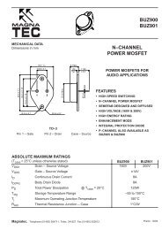
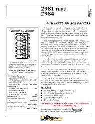
V DD500 pFPEI D0.01 µFCERAMICPULSEGENERATORCARRY INRUP/DOWNCLOCKP1P2P3P4Q1Q2Q3Q4CARRYOUTC LC LC LC LC LCLOCK20 ns 20 ns50%90%VARIABLEWIDTH10%V DDV SSFigure 1. Power Dissipation Test Circuit and WaveformV DDPROGRAMMABLEPULSEGENERATORPEP1P2P3P4Q1CARRY INR Q2UP/DOWNCLOCK Q3Q4CARRYOUTV SSC LC LC LC LC LCARRY IN ORUP/DOWNCLOCKPRESET ENABLEQ1 OR CARRY OUTRESETt su50%50%t rem20 nsw(H)OUT ONLYt TLH90%90%10% 10%t PHLt THL t PLHt PLHt1fclV DDV SSV DDV SSV DDV SSV OHV OLV DDV SSFigure 2. Switching Time Test Circuit and WaveformsMC14510B354MOTOROLA CMOS LOGIC DATA
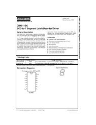
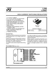
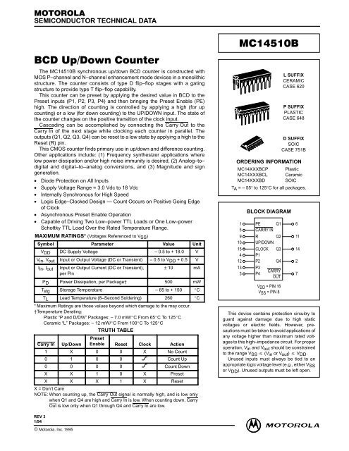
PIN DESCRIPTIONSINPUTSP1, P2, P3, P4, Preset Inputs (Pins 4, 12, 13, 3) — Dataon these inputs is loaded into the counter when PE is takenhigh.Carry In, (Pin 5) — Active–low input used when cascadingstages. Usually connected to Carry Out of the previousstage. While high, clock is inhibited.Clock, (Pin 15) — BCD data is incremented or decremented,depending on the direction of count, on the positivetransition of this signal.OUTPUTSQ1, Q2, Q3, Q4, BCD outputs (Pins 6, 11, 14, 2) — BCDdata is present on these outputs with Q1 corresponding tothe least significant bit.Carry Out, (Pin 7) — Used when cascading stages, thispin is usually connected to Carry In of the next stage. Thissynchronous output is active low and may also be used toindicate terminal count.CONTROLSPE, Preset Enable (Pin 1) — Asynchronously loads dataon the Preset Inputs. This pin is active high and will inhibit theclock when high.R, Reset, (Pin 9) — Asynchronously resets the Q outputsto a low state. This pin is active high and will inhibit the clockwhen high.Up/Down, (Pin 10) — Controls the direction of count: highfor up count, low for down count.SUPPLY PINSVSS, Negative Supply Voltage, (Pin 8) — This pin isusually connected to ground.VDD, Positive Supply Voltage, (Pin 16) — This pin is connectedto a positive supply voltage ranging from 3.0 Vdc to18.0 Vdc.PRESETENABLE0 = COUNT1 = PRESET1 = UP0 = DOWNQ1 Q2 Q3 Q4 Q5 Q6 Q7 Q8Q1 Q2 Q3 Q4 Q1 Q2 Q3 Q4PEPEC inCLOCKU/DL.S.D.MC14510BC outC inCLOCKRRP1 P2 P3 P4 P1 P2 P3 P4U/DM.S.D.MC14510BC outTERMINALCOUNTINDICATORP1 P2 P3 P4 P5 P6 P7 P8CLOCK+ V DDRESETOPEN = COUNT+ V DDTHUMBWHEEL SWITCHES(OPEN FOR “0”)+ V DDRESISTORS = 10 kΩNote: The Least Significant Digit (L.S.D.) counts from a preset value once Preset Enable (PE) goes low. The Most SignificantDigit (M.S.D.) does not change while Cin is high. When the count of the L.S.D. reaches 0 (count down mode) or reaches 9(count up mode), Cout goes low for one complete clock cycle, thus allowing the next counter to decrement/increment onecount. The L.S.D. now counts through another cycle (10 clock pulses) and the above cycle is repeated.Figure 3. Presettable Cascaded 8–Bit Up/Down CounterMC14510B356MOTOROLA CMOS LOGIC DATA
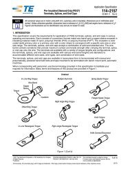
TIMING DIAGRAM FOR THE PRESETTABLECASCADED 8–BIT UP/DOWN COUNTERCLOCKUP/DOWNCARRY IN(MSD)PEP8P7P6P5P4P3P2P1CARRY OUT(MSD)Q8Q7Q6Q5Q4Q3Q2Q1CARRY OUT(LSD)RESETCOUNT MSDCOUNT LSD6 6 6 7 7 7 7 7 7 7 6 6 6 6 9 9 9 9 9 0 0 0 0 0 0 0 07 8 9 0 1 2 3 2 1 0 9 8 7 6 6 6 7 8 9 0 1 2 1 0 1 0 0PRESET ENABLEPRESETDOWNRESETENABLECOUNTUP COUNT DOWN COUNT UP COUNT UP COUNTMOTOROLA CMOS LOGIC DATAMC14510B357
OUTLINE DIMENSIONSL SUFFIXCERAMIC DIP PACKAGECASE 620–10ISSUE V–T–SEATINGPLANEF–A–16 91 8EGD 16 PL0.25 (0.010) M TN–B–ASCKLMJ 16 PL0.25 (0.010) M TBSNOTES:1. DIMENSIONING AND TOLERANCING PERANSI Y14.5M, 1982.2. CONTROLLING DIMENSION: INCH.3. DIMENSION L TO CENTER OF LEAD WHENFORMED PARALLEL.4. DIMENSION F MAY NARROW TO 0.76 (0.030)WHERE THE LEAD ENTERS THE CERAMICBODY.INCHES MILLIMETERSDIM MIN MAX MIN MAXA 0.750 0.785 19.05 19.93B 0.240 0.295 6.10 7.49C ––– 0.200 ––– 5.08D 0.015 0.020 0.39 0.50E 0.050 BSC 1.27 BSCF 0.055 0.065 1.40 1.65G 0.100 BSC 2.54 BSCH 0.008 0.015 0.21 0.38K 0.125 0.170 3.18 4.31L 0.300 BSC 7.62 BSCM 0 15 0 15N 0.020 0.040 0.51 1.01P SUFFIXPLASTIC DIP PACKAGECASE 648–08ISSUE R16H–A–1 8GF9D 16 PLBSCK0.25 (0.010) M TSEATING–T– PLANEAMJLMNOTES:1. DIMENSIONING AND TOLERANCING PER ANSIY14.5M, 1982.2. CONTROLLING DIMENSION: INCH.3. DIMENSION L TO CENTER OF LEADS WHENFORMED PARALLEL.4. DIMENSION B DOES NOT INCLUDE MOLD FLASH.5. ROUNDED CORNERS OPTIONAL.INCHES MILLIMETERSDIM MIN MAX MIN MAXA 0.740 0.770 18.80 19.55B 0.250 0.270 6.35 6.85C 0.145 0.175 3.69 4.44D 0.015 0.021 0.39 0.53F 0.040 0.70 1.02 1.77G 0.100 BSC 2.54 BSCH 0.050 BSC 1.27 BSCJ 0.008 0.015 0.21 0.38K 0.110 0.130 2.80 3.30L 0.295 0.305 7.50 7.74M 0 10 0 10S 0.020 0.040 0.51 1.01MOTOROLA CMOS LOGIC DATAMC14510B359
OUTLINE DIMENSIONSD SUFFIXPLASTIC SOIC PACKAGECASE 751B–05ISSUE J–T–SEATINGPLANE16 91 8G–A–D 16 PLK–B–P 8 PL0.25 (0.010) M B SC0.25 (0.010) M T B S A SMR X 45JFNOTES:1. DIMENSIONING AND TOLERANCING PER ANSIY14.5M, 1982.2. CONTROLLING DIMENSION: MILLIMETER.3. DIMENSIONS A AND B DO NOT INCLUDEMOLD PROTRUSION.4. MAXIMUM MOLD PROTRUSION 0.15 (0.006)PER SIDE.5. DIMENSION D DOES NOT INCLUDE DAMBARPROTRUSION. ALLOWABLE DAMBARPROTRUSION SHALL BE 0.127 (0.005) TOTALIN EXCESS OF THE D DIMENSION ATMAXIMUM MATERIAL CONDITION.MILLIMETERS INCHESDIM MIN MAX MIN MAXA 9.80 10.00 0.386 0.393B 3.80 4.00 0.150 0.157C 1.35 1.75 0.054 0.068D 0.35 0.49 0.014 0.019F 0.40 1.25 0.016 0.049G 1.27 BSC 0.050 BSCJ 0.19 0.25 0.008 0.009K 0.10 0.25 0.004 0.009M 0 7 0 7P 5.80 6.20 0.229 0.244R 0.25 0.50 0.010 0.019Motorola reserves the right to make changes without further notice to any products herein. Motorola makes no warranty, representation or guarantee regardingthe suitability of its products for any particular purpose, nor does Motorola assume any liability arising out of the application or use of any product or circuit,and specifically disclaims any and all liability, including without limitation consequential or incidental damages. “Typical” parameters which may be providedin Motorola data sheets and/or specifications can and do vary in different applications and actual performance may vary over time. All operating parameters,including “Typicals” must be validated for each customer application by customer’s technical experts. Motorola does not convey any license under its patentrights nor the rights of others. Motorola products are not designed, intended, or authorized for use as components in systems intended for surgical implantinto the body, or other applications intended to support or sustain life, or for any other application in which the failure of the Motorola product could create asituation where personal injury or death may occur. Should Buyer purchase or use Motorola products for any such unintended or unauthorized application,Buyer shall indemnify and hold Motorola and its officers, employees, subsidiaries, affiliates, and distributors harmless against all claims, costs, damages, andexpenses, and reasonable attorney fees arising out of, directly or indirectly, any claim of personal injury or death associated with such unintended orunauthorized use, even if such claim alleges that Motorola was negligent regarding the design or manufacture of the part. Motorola and are registeredtrademarks of Motorola, Inc. Motorola, Inc. is an Equal Opportunity/Affirmative Action Employer.How to reach us:USA/EUROPE/Locations Not Listed: Motorola Literature Distribution;JAPAN: Nippon Motorola Ltd.; Tatsumi–SPD–JLDC, 6F Seibu–Butsuryu–Center,P.O. Box 20912; Phoenix, Arizona 85036. 1–800–441–2447 or 602–303–5454 3–14–2 Tatsumi Koto–Ku, Tokyo 135, Japan. 03–81–3521–8315MFAX: RMFAX0@email.sps.mot.com – TOUCHTONE 602–244–6609ASIA/PACIFIC: Motorola Semiconductors H.K. Ltd.; 8B Tai Ping Industrial Park,INTERNET: http://Design–NET.com 51 Ting Kok Road, Tai Po, N.T., Hong Kong. 852–26629298MC14510B360◊MOTOROLA CMOS LOGIC MC14510B/D DATA