Surface Water Interaction Modelling Using Visual MODFLOW and GIS
Surface Water Interaction Modelling Using Visual MODFLOW and GIS
Surface Water Interaction Modelling Using Visual MODFLOW and GIS
- No tags were found...

You also want an ePaper? Increase the reach of your titles
YUMPU automatically turns print PDFs into web optimized ePapers that Google loves.
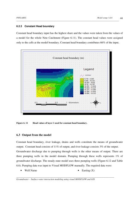
PHYLARESModel setup / ch.6__________________________________________________________________________________________446.2.3 Constant Head boundaryConstant head boundary input has the highest share <strong>and</strong> the values were taken from the values ofa model for the whole Nete Catchment (Figure 6.11). The constant head values were assignedonly to the cells at the model boundary. Constant head boundary contributes 66% of the input.Constant head boundary (m)Figure 6. 11Head values of layer 1 used for constant head boundary.6.3 Output from the modelConstant head boundary, river leakage, drains <strong>and</strong> wells constitute the means of groundwateroutput. Constant head consists of 11% of output, <strong>and</strong> river leakage consists 3% of the output.Groundwater discharge due to pumping through wells is the other means of output. There arethree pumping wells in the model domain. Pumping through these wells represents 1% ofgroundwater discharge. The steady-state model uses three pumping wells (Figure 6.12 <strong>and</strong> Table6.6). Pumping data was input to <strong>Visual</strong> <strong>MODFLOW</strong> manually. The required data were:• Well Name• Easting (X)______________________________________________________________________________________Groundwater – <strong>Surface</strong> water interaction modeling using visual <strong>MODFLOW</strong> <strong>and</strong> <strong>GIS</strong>