Surface Water Interaction Modelling Using Visual MODFLOW and GIS
Surface Water Interaction Modelling Using Visual MODFLOW and GIS
Surface Water Interaction Modelling Using Visual MODFLOW and GIS
- No tags were found...

You also want an ePaper? Increase the reach of your titles
YUMPU automatically turns print PDFs into web optimized ePapers that Google loves.
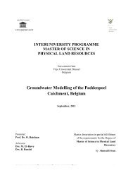
PHYLARESModel calibration / ch.7__________________________________________________________________________________________497.2 Calibrated Aquifer Parameters7.2.1 Hydraulic conductivityCalibrated hydraulic conductivities are shown in Table 7.2. The optimum hydraulic conductivityvalues for the various hydrogeologic units were taken from the literature (Solomon, T, 2006) <strong>and</strong>are indicated in Table --. Layer 1 was calibrated at a horizontal Hydraulic conductivity value of15 m/d <strong>and</strong> vertical hydraulic conductivity of 1.5 m/d. Layer 2 was calibrated at 6 <strong>and</strong> 0.6 m/d asthe vertical <strong>and</strong> horizontal hydraulic conductivities respectively. Layer 3 was calibrated at 5 m/d<strong>and</strong> 0.5 m/d for the horizontal <strong>and</strong> vertical hydraulic conductivities respectively. The initialvalues for the calibration of hydraulic properties were taken from past literature of Solomon T,2007.Table 7. 2Calibrated Hydraulic conductivity values for the three layersItem Layer 1 Layer 2 Layer 3Horizontal Hydraulic conductivity15 6 5(m/d)Vertical Hydraulic conductivity(m/d)1.5 0.6 0.57.2.2 <strong>Water</strong> levelsModel water levels <strong>and</strong> measured water levels are compared. Each red dot in Figure 7.2 plots anobservation well’s simulated water level with field-measured water level. A perfect match wouldplot along the blue line. The RMSE as seen is 0.094 meters.______________________________________________________________________________________Groundwater – <strong>Surface</strong> water interaction modeling using visual <strong>MODFLOW</strong> <strong>and</strong> <strong>GIS</strong>