Operating Instructions - MEI's On-line Technical Support
Operating Instructions - MEI's On-line Technical Support
Operating Instructions - MEI's On-line Technical Support

You also want an ePaper? Increase the reach of your titles
YUMPU automatically turns print PDFs into web optimized ePapers that Google loves.
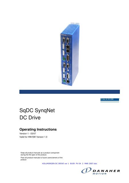
SqDC SynqNet<br />
DC Drive<br />
<strong>Operating</strong> <strong>Instructions</strong><br />
Version 1 - 03/07<br />
Valid for HW/SW Version 1.0<br />
Keep all product manuals as a product component<br />
during the life span of the product.<br />
Pass all product manuals to future users/owners of the<br />
product<br />
KOLLMORGEN DC DRIVE ver 1 B109 PV 04 2 MAR 2007.doc
KOLLMORGEN Version 1 -11/07 Revision History<br />
Revision History<br />
Rev Date Valid For Description<br />
1.0 OCT 2006 HW/SW Versions 1.0 New Quick start Guide<br />
1.1 FEB 2007 same Quick Start Guide rewritten<br />
Important Notice<br />
Copyright© Kollmorgen Servotronix Ltd 2007<br />
Kollmorgen Servotronix Ltd holds the copyright to this manual. All rights are reserved<br />
and no part of this publication may be reproduced or transmitted in any form or by any means<br />
without prior written consent from Kollmorgen Servotronix Ltd.<br />
Disclaimer<br />
The information in this manual was accurate and reliable at the time of its release. However,<br />
Kollmorgen Servotronix Ltd. reserves the right to change the specifications of the product<br />
described in this manual without notice at any time.<br />
This document contains proprietary and confidential information of Kollmorgen Servotronix<br />
Ltd. The contents of the document may not be disclosed to third parties, translated, copied or<br />
duplicated in any form, in whole or in part, without the express written permission of<br />
Kollmorgen Servotronix Ltd.<br />
Registered Trademarks<br />
All other proprietary names mentioned in this manual are the trademarks of their respective<br />
owners.<br />
Print Version 004<br />
March 2007<br />
SqDC SynqNet DC Drive i
KOLLMORGEN Version 1 -11/07 Important Safety Information<br />
How to Contact Us<br />
Danaher Motion is committed to quality customer service. Our goal is to provide<br />
the customer with information and resources as soon as they are needed. In<br />
order to serve in the most effective way, contact your local sales representative<br />
for order status and delivery information, product information and literature,<br />
and application and field technical assistance. If you are unaware of who your<br />
local sales representative is, please contact us at:<br />
Email: sep@danahermotion.com and specify SynqNet <strong>Support</strong> in the subject<br />
<strong>line</strong>.<br />
Important Safety Information<br />
The information found in this section is designed for your safety and the<br />
prevention of needless repairs to the machine.<br />
Operational Warnings and Cautions<br />
DANGER<br />
Danger means that the situation described will cause death or injury to<br />
you or someone else if the safety information is not obeyed.<br />
NOTE<br />
Please take note of the fact that…...<br />
CAUTION<br />
Caution means that the situation described could cause damage to the<br />
equipment or the program.<br />
WARNING<br />
Warning means that the situation described can cause damage to either<br />
the equipment or the program and we recommend that only an<br />
experienced operator should perform these adjustments.<br />
SqDC SynqNet DC Drive ii
KOLLMORGEN Version 1 -11/07 Contents<br />
Contents<br />
REVISION HISTORY ..................................................................................................I<br />
IMPORTANT NOTICE .................................................................................................I<br />
HOW TO CONTACT US ............................................................................................ II<br />
IMPORTANT SAFETY INFORMATION ............................................................................ II<br />
Operational Warnings and Cautions.................................................................. ii<br />
1 INTRODUCTION ...............................................................................................................1<br />
1.1 ABOUT THIS GUIDE.........................................................................................1<br />
1.1.1 Downloading Manuals from our Website ............................................... 1<br />
2 PRE-INSTALLATION REQUIREMENTS .........................................................................3<br />
2.1 LAB ELECTRICAL REQUIREMENTS .....................................................................3<br />
2.2 REQUIRED CABLES ........................................................................................3<br />
2.3 MOTION CONTROL CARD (DMPC) ....................................................................4<br />
2.3.1 What is SynqNet.................................................................................. 4<br />
2.3.2 Acquiring the Latest SynqNet Software Version ..................................... 4<br />
2.3.3 PC Requirements ................................................................................ 4<br />
3 INSTALLING THE HARDWARE ......................................................................................5<br />
3.1 UNPACKING INSTRUCTIONS..............................................................................5<br />
3.2 GENERAL .....................................................................................................6<br />
3.2.1 Safety ................................................................................................. 6<br />
3.2.2 Grounding ........................................................................................... 6<br />
3.3 CONNECTING THE DRIVE CABLES......................................................................7<br />
4 INSTALLING THE DMPC CONTROLLER CARD............................................................8<br />
4.1 INSTALLING THE DMPC CONTROLLER CARD.......................................................8<br />
4.2 INSTALLING THE DMPC DRIVERS......................................................................8<br />
4.3 INSTALLING THE MOTION CONSOLE PROGRAM...................................................12<br />
5 USING THE MOTION CONSOLE...................................................................................13<br />
5.1 LOADING THE MOTION CONSOLE.....................................................................13<br />
5.2 CONFIGURING THE MOTOR PARAMETERS..........................................................17<br />
5.2.1 Uploading the Motor Parameters (get command) ................................. 17<br />
5.2.2 Editing the Motor Configuration File .................................................... 18<br />
5.2.3 Downloading the Motor Parameters (Set command) ............................ 19<br />
5.3 CONFIGURING THE MOTION CONTROL CONSOLE ................................................19<br />
5.3.1 Mapping the Axes .............................................................................. 20<br />
5.3.2 Setting the Filter Parameters (PID Coefficients) ................................... 20<br />
5.3.3 Setting the Motor Configuration Parameters ........................................ 21<br />
5.3.4 Clearing the Errors............................................................................. 23<br />
5.3.5 Setting the Axes Motion Parameters ................................................... 23<br />
5.3.6 Set Amp Enable ................................................................................ 24<br />
5.3.7 Start and Stop the Motors................................................................... 25<br />
SqDC SynqNet DC Drive iii
KOLLMORGEN Version 1 -11/07 Contents<br />
6 ERROR MESSAGES ......................................................................................................26<br />
6.1 USING THE SQDRIVEMSG UTILITY....................................................................26<br />
6.1.1 Example............................................................................................ 27<br />
6.1.2 Error Messages ................................................................................. 27<br />
APPENDIX A HARDWARE SPECIFICATIONS....................................................................................28<br />
A.1 MECHANICAL ..............................................................................................28<br />
A.1.1 Physical Characteristics ..................................................................... 28<br />
A.1.2 Front Panel ....................................................................................... 28<br />
A.1.3 Weight .............................................................................................. 28<br />
A.2 ELECTRICAL SPECIFICATIONS.........................................................................29<br />
A.3 ENVIRONMENTAL SPECIFICATIONS...................................................................30<br />
APPENDIX B CONFIGURATION FILE PARAMETERS .......................................................................31<br />
B.1 PEAK CURRENT LEVEL .................................................................................31<br />
B.2 HEAT-SINK TEMPERATURE.............................................................................32<br />
B.3 BUS VOLTAGE.............................................................................................32<br />
APPENDIX C ENCODERS ....................................................................................................................33<br />
C.1 INCREMENTAL ENCODERS .............................................................................33<br />
C.1.1 Single Ended ABI Encoders ............................................................... 33<br />
C.1.2 Differential ABI Encoders ................................................................... 34<br />
C.2 ABSOLUTE ENCODERS..................................................................................34<br />
APPENDIX D CONNECTOR PIN-OUTS ...............................................................................................35<br />
D.1 LOGIC POWER.............................................................................................35<br />
D.2 BUS POWER ...............................................................................................35<br />
D.3 MOTOR CONNECTOR ....................................................................................36<br />
D.4 ENCODER CONNECTOR .................................................................................36<br />
SqDC SynqNet DC Drive iv
KOLLMORGEN Version 1 -11/07 Introduction<br />
1.1 About this Guide<br />
Chapter 1<br />
1 INTRODUCTION<br />
This guide is written for integration engineers that want to create a working<br />
environment on the test bench. Installation and step by step setup instructions<br />
are included.<br />
A more detailed description of the system is provided in the SqDC <strong>Technical</strong><br />
Manual which is included together with our applications notes, in Acrobat-<br />
Reader format on the accompanying CD-ROM in multiple languages. You can<br />
print out this documentation on any standard commercial printer. You can also<br />
purchase a printed copy of the documentation from us at the following E-mail<br />
address sep@danahermotion.com and specify SynqNet <strong>Support</strong> in the subject<br />
<strong>line</strong>.<br />
It is strongly recommended that only suitable personnel install and setup the<br />
system.<br />
1. The guide is divided into the following sections<br />
2. Unpacking the Drive<br />
3. Drive Hardware Setup<br />
4. SynqNet Installation<br />
5. Configuring the SynqNet Motion Console<br />
6. Configuring the Drive Parameters<br />
7. <strong>Operating</strong> the Drive<br />
1.1.1 Downloading Manuals from our Website<br />
You can use the link www.DanaherMotion.com to download our product<br />
manuals from the DanaherMotion website.<br />
SqDC SynqNet DC Drive 1
KOLLMORGEN Version 1 -11/07 Installing Hardware<br />
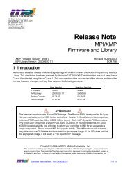
1.1.2 Product Identification<br />
Check the product labeling on the packaging and the product and confirm that<br />
you have received the correct product, SqDC4. This can be confirmed from the<br />
product label which should conform to that illustrated below<br />
SqDC SynqNet DC Drive 2
KOLLMORGEN Version 1 -11/07 Pre-Installation Requirements<br />
Chapter 2<br />
2 PRE-INSTALLATION REQUIREMENTS<br />
This section describes all the equipment required to test drive the stepper drive.<br />
2.1 Lab Electrical Requirements<br />
The following equipment must be readily available in order to install and setup<br />
the SqDC SynqNet DC Drive and the SynqNet PC controller.<br />
Table 1: Electrical Requirements<br />
Requirement Description<br />
Bus Power Supply<br />
Power Supply Type Unregulated or Regulated<br />
Output Voltage 12 to 42 Volts<br />
Output Current 1.5 to 10 Amps<br />
Current Limit Adjustable<br />
Logic Power Supply<br />
Power Supply Type Regulated<br />
Output Voltage 24V +-10%<br />
Output Current 1A<br />
DC Motors???<br />
The output current depends on motor selection, load<br />
and power supply voltage.<br />
DC Motor Type Permanent Magnet Brushed DC (PMDC)<br />
Voltage 0 - 42 Vdc<br />
Current 3A rms (MAX), 4.5A peak (MAX)<br />
2.2 Required Cables<br />
See Appendix D Connector Pin-Outs on page 35 for the information required to<br />
build the cables<br />
SqDC SynqNet DC Drive 3
KOLLMORGEN Version 1 -11/07 Pre-Installation Requirements<br />
2.3 Motion Control Card<br />
You need to acquire a SynqNet PC controller card from Danaher Motion<br />
Performance Controls (DMPC) as the motion control of the motor is performed<br />
by this card.<br />
2.3.1 What is SynqNet<br />
SynqNet is a high-performance; synchronous network technology specifically<br />
designed for multi-axis motion control applications. It is the only system that<br />
dramatically reduces system wiring while simultaneously provides higher<br />
performance than conventional analog control systems.<br />
2.3.2 Acquiring the Latest SynqNet Software Version<br />
You must download the latest version of the SynqNet MPI software for your<br />
card from the DMPC support site. Use the Download tab on the website.<br />
When downloading the software you are prompted to get a password to unzip<br />
the downloaded file.<br />
NOTE<br />
The MPI-setup version must be 03.04.00 or later.<br />
For further details please visit to the Danaher Motion Performance Controls<br />
Website: http://www.motioneng.com/<br />
2.3.3 PC Requirements<br />
Any PC running:<br />
� Microsoft Windows 2000 or better<br />
� Acrobat reader version 5 or better<br />
� Internet browser (IE recommended)<br />
SqDC SynqNet DC Drive 4
KOLLMORGEN Version 1 -11/07 Installing the Hardware<br />
This section includes the:<br />
� Unpacking the hardware<br />
Chapter 3<br />
3 INSTALLING THE HARDWARE<br />
� General information on installing the SynqNet system<br />
� IMPORTANT safety information<br />
� Grounding information<br />
� Connecting the drive cables<br />
3.1 Unpacking <strong>Instructions</strong><br />
Upon receipt of the equipment, inspect the components to ensure that no<br />
damage has occurred during shipment. If damage has occurred, notify the<br />
carrier immediately. Check all shipping material for connector kits,<br />
documentation, diskettes, CD-ROM, or other small pieces of equipment before<br />
disposing of the packing material.<br />
IMPORTANT INFORMATION<br />
Do not dispose of shipping materials until the packing list has been<br />
thoroughly checked and all items accounted for.<br />
When removing all packing material and equipment from the shipping<br />
container be aware that some of the shipped items may be small enough<br />
to be accidentally discarded.<br />
ESD WARNING<br />
Electronic components in this equipment are design-hardened to reduce<br />
sensitivity to ESD (Electro Static Discharge) however, proper procedures<br />
should be taken when handling the equipment to avoid any damage.<br />
SqDC SynqNet DC Drive 5
KOLLMORGEN Version 1 -11/07 Installing the Hardware<br />
3.2 General<br />
3.2.1 Safety<br />
These installation steps are designed to lead you through the proper installation<br />
and setup of the SynqNet system. They were developed with the assumption<br />
that you have a fundamental understanding of basic electronics, computers,<br />
mechanics, and proper safety practices. However, you do not have to be an<br />
expert in motion control to install and operate the drive system. It is<br />
recommended that you read the entire manual completely before attempting<br />
installation or operating the equipment.<br />
DANGER<br />
High voltages could be present as well as dangerous and hazardous<br />
conditions.<br />
3.2.2 Grounding<br />
Be certain to follow all national and local codes during installation.<br />
System grounding is essential for proper performance of the drive system. A<br />
ground bus bar may be used as a single point ground for the system. Safety<br />
grounding should be provided to all pieces of the system from a star point. In<br />
addition to the safety grounding, a high frequency ground must be provided<br />
that connects the back panel to the enclosure and, ultimately, to earth ground.<br />
The objective is to provide an extremely low impedance path between the<br />
filters, drives, power supplies, and earth ground.<br />
This high frequency ground is accomplished with the use of a flat braid or<br />
copper bus bar. It is important not to rely on a standard wire for the high<br />
frequency ground. In general, a wire has an inductance of 8nH-per-inch,<br />
regardless of diameter. At higher frequencies because the voltage runs on the<br />
surface of the conductor, this unwanted inductance between grounds equates to<br />
limited filter performance.<br />
NOTE<br />
When connecting high frequency grounds, use the shortest braided ribbon<br />
or braided cable as possible.<br />
SqDC SynqNet DC Drive 6
KOLLMORGEN Version 1 -11/07 Installing the Hardware<br />
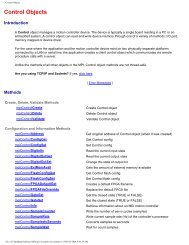
3.3 Connecting the Drive Cables<br />
1. Before connecting the cables ensure that the power source is powered OFF.<br />
2. Use Figure 1 and the two tables below to connect the cables.<br />
3. When all the power cables are connected, turn on the power source.<br />
4. Connect the communications cable.<br />
Table 2: Cable Connection Chart<br />
Figure 1: Front Cable Connection Panel<br />
STEP Connect Cable To Description<br />
1 24V Logic Power P7 12 to 42 Volts at 12 Amps.<br />
2 Encoder C1 to C4 Motor encoders 0 to 3.<br />
3 DC Bus (Input) P3 and P6 DC power for driving the motors (12 to 42 Volts and<br />
12 Amps).<br />
4 Motor Power<br />
Pin 2 Phase A +<br />
Pin 3 Phase A-<br />
P1, P2, P4<br />
and P5<br />
Maximum Output Rating is 50V at 5 Amps.<br />
5 Communication IN C7 Connect one end of the SynqNet communications<br />
cable to the IN connector. The other end connects<br />
to the Motion Control card when it is installed to the<br />
PC.<br />
Table 3: Connector Grouped by Axis<br />
Plug Group Axis 0 Axis 1 Axis 2 Axis 3<br />
Encoder Encoder 0 (C1) Encoder 1 (C2) Encoder 2 (C3) Encoder 3 (C3)<br />
Output Power M0 (P1) M1 (P2) M2 (P4) M3 (P5)<br />
Input Bus B0 (P3) B1 (P6)<br />
SqDC SynqNet DC Drive 7
KOLLMORGEN Version 1 -11/07 Installing MEI Controller Card<br />
Chapter 4<br />
4 INSTALLING THE DMPC CONTROLLER CARD<br />
This section installs the:<br />
� DMPC Controller card<br />
� The DMPC Drivers<br />
� SynqNet communication cable that is connected to the drive<br />
4.1 Installing the DMPC Controller Card<br />
1. Install the SynqNet motion controller card using the instructions you<br />
received from the manufacturer.<br />
2. Connect the communication cable that has one side connected to the motor<br />
drive to the OUT connector on the newly installed SynqNet card.<br />
4.2 Installing the DMPC Drivers<br />
1. Power ON the PC.<br />
The system has found the newly installed motion controller card.<br />
SqDC SynqNet DC Drive 8
KOLLMORGEN Version 1 -11/07 Installing MEI Controller Card<br />
2. Click the button to continue.<br />
3. Click the button.<br />
4. Select the Specify a location checkbox.<br />
SqDC SynqNet DC Drive 9
KOLLMORGEN Version 1 -11/07 Installing MEI Controller Card<br />
5. Click the button.<br />
If you are running Windows NT open the folder as shown above.<br />
6. Either double-click the MEIXMP.INF file, or select it and click the<br />
button.<br />
SqDC SynqNet DC Drive 10
KOLLMORGEN Version 1 -11/07 Installing MEI Controller Card<br />
7. Click the button.<br />
8. Click the button.<br />
9. Click the button.<br />
SqDC SynqNet DC Drive 11
KOLLMORGEN Version 1 -11/07 Installing MEI Controller Card<br />
4.3 Installing the Motion Console Program<br />
1. Install the file 03.04.XX_WinNTSetup.exe (or later version) on your PC.<br />
If you did not receive this file either download it from our website<br />
http://support.motioneng.com/.<br />
To open the program you are required to get a password from<br />
support@motioneng.com. Installing this file places the Motion Console<br />
icon on the desktop.<br />
2. From the desktop, click the icon.<br />
3. Click the button.<br />
The necessary firmware version is displayed on the top of the window (625).<br />
4. Select the XMPxxx.bin file.<br />
Downloads the binary image to the SqNode.<br />
5. Click the button.<br />
SqDC SynqNet DC Drive 12
KOLLMORGEN Version 1 -11/07 Using the Motion Console<br />
Chapter 5<br />
5 USING THE MOTION CONSOLE<br />
This section describes in a step-by-step format how to:<br />
� Use the Motion Console to synchronize the SynqNet to the drive<br />
� Configuring the motor parameters using a text editor<br />
� Configuring the motion control console<br />
5.1 Loading the Motion Console<br />
� To load the motion console application:<br />
1. If the Motion Console is not open, then from the desktop, click the<br />
icon.<br />
2. Click the toolbar button.<br />
3. From the Object Pool pane, select the controller to add to the Object List.<br />
SqDC SynqNet DC Drive 13
KOLLMORGEN Version 1 -11/07 Using the Motion Console<br />
4. Click the button.<br />
5. Click the button.<br />
6. Click the button to synchronize the controller and drive.<br />
If the FPGA Runtime has not been previously installed the following message<br />
is displayed.<br />
SqDC SynqNet DC Drive 14
KOLLMORGEN Version 1 -11/07 Using the Motion Console<br />
7. Click the button.<br />
You are asked to select the COFE003D_0400.sff file.<br />
8. Click the button to select the file.<br />
9. Select the COFE003D_0400.sff file.<br />
The COFE003D_0400.sff file is now ready to be downloaded.<br />
SqDC SynqNet DC Drive 15
KOLLMORGEN Version 1 -11/07 Using the Motion Console<br />
10. Click the button<br />
The download progress is shown above.<br />
11. Click the button and click the Info tab.<br />
The Motion Console opens after synchronizing the controller and drive.<br />
Communication is established between the controller and the drive. The<br />
SynqNet controller is synchronized with the drive and the Yellow LEDs<br />
change from blinking to solid ON.<br />
SqDC SynqNet DC Drive 16
KOLLMORGEN Version 1 -11/07 Using the Motion Console<br />
5.2 Configuring the Motor Parameters<br />
NOTE<br />
The motor parameters can only be uploaded once the SynqNet controller is<br />
synchronized with the drive. See previous section.<br />
This section explains how to upload the motor configuration parameters from<br />
the motor drive controller using a Dos –get command to the PC and saved in<br />
the Config.dc file. <strong>On</strong>ce on the PC we can configure the parameters to suit the<br />
specific motors you want to connect to the drive controller. When the file is<br />
configured it is downloaded back onto the drive controller using a –set<br />
command.<br />
5.2.1 Uploading the Motor Parameters (get command)<br />
� To upload the motor parameters from the drive unit:<br />
1. At the command prompt, enter the following command:<br />
sqDriveconfig –get config.dc –map kollmorgen sqDC.dm<br />
This command fetches the parameters from the motor drive.<br />
2. Press the ENTER key.<br />
3. Enter Y and press the ENTER key, to the message,<br />
Do you want to overwrite the existing file (y/n)?<br />
The motor parameters for the four axes (0, 1, 2 and 3) are uploaded to<br />
the PC.<br />
SqDC SynqNet DC Drive 17
KOLLMORGEN Version 1 -11/07 Using the Motion Console<br />
4. Open the Config.ds file in any text editor.<br />
Located at: C:\MEI\XMP\BIN\WINNT.<br />
The motor parameters are shown in the example above.<br />
5.2.2 Editing the Motor Configuration File<br />
The motor parameters must now be changed to suit the specific motors that are<br />
to be connected to the drive controller. The parameters are:<br />
� Peak Current Limit Fault Level<br />
� Drive Temperature not implemented in this version (Read <strong>On</strong>ly)<br />
� Drive Bus Voltage displayed in Volts (Read <strong>On</strong>ly)<br />
5.2.2.1 Setting the Peak Current Level<br />
� To set the peak current level:<br />
Change the parameter SQSTEPParamCURRENT_LEVEL to 50 Amps.<br />
# sqNode[0] drive[0] "Kollmorgen SqDC4" "1"<br />
SQSTEPParamCURRENT_LEVEL 50.000000<br />
SQSTEPParamDRIVE_TEMP 35<br />
SQSTEPParamBUS_VOLTAGE 36.000000<br />
� Use the formula below to change the peak current level on all 4 axes.<br />
Where X: is a value between 0 and 100 and Dlpeak=4.5<br />
SqDC SynqNet DC Drive 18
KOLLMORGEN Version 1 -11/07 Using the Motion Console<br />
5.2.3 Downloading the Motor Parameters (Set command)<br />
� To download the motor parameters to the drive unit:<br />
1. At the command prompt, enter the following command:<br />
sqDriveconfig –set config.dc –map kollmorgen sqDC.dm<br />
This command downloads the parameters to the motor drive.<br />
2. Press the ENTER key.<br />
3. Enter Y and press the ENTER key, to the message,<br />
Do you want to overwrite the existing file (y/n)?<br />
The motor parameters for the four axes (0, 1, 2 and 3) are downloaded to<br />
the motor drive.<br />
5.3 Configuring the Motion Control Console<br />
This section describes how to:<br />
� Map the axes<br />
� Setting the motor configuration parameters<br />
� Clearing the errors<br />
� Setting the axes motion parameters<br />
You must perform the configuration in the sequence listed below.<br />
If the Motion Console is not installed go first to sections 4.3 Installing the<br />
Motion Console Program on page 12 and if it is installed and not loaded, go to<br />
section 5.1 Loading the Motion Console on page 13.<br />
SqDC SynqNet DC Drive 19
KOLLMORGEN Version 1 -11/07 Using the Motion Console<br />
5.3.1 Mapping the Axes<br />
1. From the toolbar, click the button.<br />
2. Add the selected controller to the Object List.<br />
3. Click the button.<br />
4. Click the Config tab if it is not selected.<br />
5. Click Axis Map to select the complete row.<br />
This selects the complete row.<br />
6. Hold down the Shift key and click the left-hand button.<br />
7. Click to configure the sub-object list to default mapping.<br />
5.3.2 Setting the Filter Parameters (PID Coefficients)<br />
1. From the toolbar, click the button.<br />
In this example the controller is already added.<br />
SqDC SynqNet DC Drive 20
KOLLMORGEN Version 1 -11/07 Using the Motion Console<br />
2. From the Object Pool select the controller to add to the Object List.<br />
3. Click the button.<br />
4. Click the button and click the Coeffs tab.<br />
5. For all four axes, enter the value of 100 for the Kp and Ki filters.<br />
5.3.3 Setting the Motor Configuration Parameters<br />
This section is used to set the motor parameters.<br />
1. From the toolbar, click the button.<br />
In this example the controller is already added.<br />
2. From the Object Pool select the controller to add to the Object List.<br />
SqDC SynqNet DC Drive 21
KOLLMORGEN Version 1 -11/07 Using the Motion Console<br />
3. Click the button.<br />
4. Click the button.<br />
5. Set the Type to Servo for all four axes.<br />
6. If you are using single ended encoders disable Primary Feedback Fault.<br />
If not skip this step.<br />
a. Clear the Primary Feedback Fault checkbox under Fault Config.<br />
b. Ensure that the Fault Config value is now 0X00000006.<br />
If not change it manually.<br />
7. If you are using differential encoders ensure that the Fault Config value is<br />
0X00000016.<br />
SqDC SynqNet DC Drive 22
KOLLMORGEN Version 1 -11/07 Using the Motion Console<br />
8. Click the Events tab.<br />
9. Except for Amp Fault Action set the other fault actions to None.<br />
10. Set the Encoder Fault action to:<br />
For Encoder Type Enter the Value<br />
Single Ended None<br />
Differential E-Stop/Abort<br />
5.3.4 Clearing the Errors<br />
1. From the toolbar, click the button.<br />
2. Click the Action tab.<br />
3. Click the green Clear Fault button for each of the motors.<br />
The red LEDs on the drive turn OFF.<br />
5.3.5 Setting the Axes Motion Parameters<br />
This section controls the motion of the motor.<br />
SqDC SynqNet DC Drive 23
KOLLMORGEN Version 1 -11/07 Using the Motion Console<br />
1. From the toolbar, click the button.<br />
2. Add the selected controller to the Object List.<br />
3. Click the button.<br />
4. Set the motion following parameters on each axis:<br />
a. Position 1 and Position 2<br />
b. Velocity<br />
c. Acceleration<br />
d. Deceleration<br />
NOTE<br />
5.3.6 Set Amp Enable<br />
All the other values are optional and can be set as required.<br />
1. From the toolbar, click the button.<br />
2. Select the Amp Enabled checkbox (Enabled) for each motor.<br />
SqDC SynqNet DC Drive 24
KOLLMORGEN Version 1 -11/07 Using the Motion Console<br />
5.3.7 Start and Stop the Motors<br />
1. From the toolbar, click the button.<br />
2. Click the Actions tab.<br />
3. Click Zero Position for all axes.<br />
4. Click Clear Fault for all axes.<br />
5. Select the Repeat Mode checkboxes (Enabled) for each motor.<br />
6. Click to move the motor to position 1.<br />
7. Click to move the motor to the furthest position.<br />
8. Click to move the motor to position 2.<br />
NOTE<br />
Click the Abort button to force an error and then clear it by<br />
clicking the Clear Fault button.<br />
SqDC SynqNet DC Drive 25
KOLLMORGEN Version 1 -11/07 Error Messages<br />
Chapter 6<br />
6 ERROR MESSAGES<br />
The sqDriveMsg Utility displays all the faults and warnings present on the<br />
specified drive.<br />
6.1 Using the sqDriveMsg Utility<br />
� Use Table 4 below as a guide to find the required faults and warnings.<br />
Table 4 sqDriveMsg Utility Arguments<br />
Argument Description<br />
-? Help<br />
-control # Controller number (default=0).<br />
-server # Name or IP address of the host running server.exe.<br />
-port # TCP/IP port on the host computer (default=3300).<br />
-trace # Bit mask to specify trace information outputs.<br />
-node # Node address of the SynqNet network (default=0).<br />
-drive # Index of the drive relative to the node (default=0).<br />
-motor # The MPI motor object mapped to the drive (default=0).<br />
NOTE<br />
You can use either –node and –drive, or just –motor to specify the desired<br />
drive interface.<br />
SqDC SynqNet DC Drive 26
KOLLMORGEN Version 1 -11/07 Error Messages<br />
6.1.1 Example<br />
6.1.2 Error Messages<br />
Table 5 sqDriveMsg Utility Drive Faults for DC Motors<br />
Drive Fault Description sqDC<br />
Bits<br />
Over Current Global drive fault will effect both axes. 0<br />
Bus Over Voltage Global drive fault will effect both axes. 1<br />
Over Temparature Global drive fault will effect both axes. 2<br />
Bus Under Voltage Global drive fault will effect both axes. 3<br />
Table 6 sqDriveMsg Utility Axes Faults for DC Motors<br />
Axes Fault Description sqDC<br />
Bits<br />
Axis_0_Current Limit Axis 0 Current Limit Fault 5<br />
Axis_1_Current Limit Axis 1 Current Limit Fault 7<br />
SqDC SynqNet DC Drive 27
KOLLMORGEN Version 1 -11/07 Hardware Specifications<br />
Appendix A HARDWARE SPECIFICATIONS<br />
A.1 Mechanical<br />
The SqDC SynqNet DC Drive provides a 4 axis small motor servo drive with a<br />
compact footprint. The figure below illustrates the system dimensions and the<br />
connector interfaces, which are all situated on the front of the unit. The unit can<br />
be positioned vertically or horizontally with mounting holes provided on the Lbracket<br />
for installing on any surface.<br />
A.1.1 Physical Characteristics<br />
Depth<br />
120 mm<br />
A.1.2 Front Panel<br />
A.1.3 Weight<br />
Figure 2: Physical Dimensions<br />
Figure 3: SqDC4 Front Panel Silk<br />
Total weight without cables is 1.1 Kilograms.<br />
SqDC SynqNet DC Drive 28
KOLLMORGEN Version 1 -11/07 Configuration File Parameters<br />
A.2 Electrical Specifications<br />
Table 7: Electrical Specifications<br />
Specifications Test Condition MIN TYP MAX Unit<br />
Bus voltage 12 - 42 V<br />
Logic Voltage 18 24 28 V<br />
Phase output<br />
Current<br />
Phase Output<br />
Current<br />
Logic<br />
Quiescent<br />
Current<br />
Active Power<br />
Dissipation<br />
Encoder<br />
Voltage Supply<br />
Encoder<br />
Current Supply<br />
GPIO Input<br />
Voltage<br />
GPIO Output<br />
Current<br />
GPIO Output<br />
Vce<br />
RMS<br />
Peak<br />
I/O Floating<br />
I out(per axis)=3Arms<br />
0.4 3 Arms<br />
0.57 4.5 Apeak<br />
250 mA<br />
12 W<br />
4.5 5 5.5 V<br />
100 250 mA<br />
2 30 V<br />
0 15 60 mA<br />
High Speed I/O RS-422/485 Standard 1MB/s 10MB/s<br />
40 V<br />
SqDC SynqNet DC Drive 29
KOLLMORGEN Version 1 -11/07 Configuration File Parameters<br />
A.3 Environmental Specifications<br />
Table 8: Environmental Specifications<br />
Specifications Description<br />
Ambient Temperature 0 to +50 Degrees C<br />
Storage Temperature -20 to 70 Degrees C<br />
Maximum L-Bracket<br />
Temperature<br />
Current per axis without<br />
additional heat-sinking<br />
70 Degree C<br />
~1.5 Arms<br />
Ambient Humidity 10% to 90%, non condensing<br />
Atmosphere Without corrosive gasses or dust<br />
Altitude De-rated 5% per 1000ft (300m) above 3300ft<br />
(1000m)<br />
Vibration 0.5 G<br />
DANGER<br />
Additional cooling may be required to limit the plate temperature to 70°C<br />
when operating the unit at higher currents across multiple axes.<br />
IMPORTANT NOTE<br />
This does not limit the peak transient current limit of 5A per axis only the<br />
continuous rated value.<br />
SqDC SynqNet DC Drive 30
KOLLMORGEN Version 1 -11/07 Configuration File Parameters<br />
Chapter 7<br />
Appendix B CONFIGURATION FILE PARAMETERS<br />
The motor parameters must now be changed to suit the specific motors that are<br />
to be connected to the drive controller. The parameters are:<br />
� Peak Current Level<br />
� Drive Temperature (Read <strong>On</strong>ly)<br />
� Drive Bus Voltage displayed in Volts (Read <strong>On</strong>ly)<br />
# sqNode[0] drive[0] "Kollmorgen SqDC4" "1"<br />
SQSTEPParamCURRENT_LEVEL 0.000000<br />
SQSTEPParamDRIVE_TEMP 36<br />
SQSTEPParamBUS_VOLTAGE 37.500000<br />
# sqNode[0] drive[1] "Kollmorgen SqDC4" "1"<br />
SQSTEPParamCURRENT_LEVEL 0.000000<br />
SQSTEPParamDRIVE_TEMP 36<br />
SQSTEPParamBUS_VOLTAGE 37.500000<br />
# sqNode[0] drive[2] "Kollmorgen SqDC4" "1"<br />
SQSTEPParamCURRENT_LEVEL 0.000000<br />
SQSTEPParamDRIVE_TEMP 36<br />
SQSTEPParamBUS_VOLTAGE 37.000000<br />
# sqNode[0] drive[3] "Kollmorgen SqDC4" "1"<br />
SQSTEPParamCURRENT_LEVEL 0.000000<br />
SQSTEPParamDRIVE_TEMP 36<br />
SQSTEPParamBUS_VOLTAGE 37.000000<br />
B.1 Peak Current Level<br />
Amplitude of the sine wave produced as a percentage of the drive peak rated<br />
current which is 4.5 Amps.<br />
Where X: is a value between 0 and 100 and Dlpeak=4.5<br />
SqDC SynqNet DC Drive 31
KOLLMORGEN Version 1 -11/07 Configuration File Parameters<br />
B.2 Heat-sink Temperature<br />
This parameter is READ-ONLY and provides the temperature of the heatsink in<br />
degrees Celsius.<br />
� Valid operating range from 10-80°C (50-176°F)<br />
� Accuracy of reading ±3%<br />
NOTE<br />
The over-temperature fault is set at 70°C (158°F).<br />
B.3 Bus Voltage<br />
This parameter is READ-ONLY and provides the voltage of the DC bus in volts.<br />
� Valid measuring range from 0-96 Volts<br />
� Accuracy of reading ±1%<br />
NOTE<br />
The over-voltage fault is set at 48 Volts (DC).<br />
SqDC SynqNet DC Drive 32
KOLLMORGEN Version 1 -11/07 Encoders<br />
Appendix C ENCODERS<br />
Two encoder options are available for use with the SqDC:<br />
� Incremental (ABI) Encoder<br />
� Absolute SSI based Encoder<br />
C.1 Incremental Encoders<br />
The SynqNet system can accommodate incremental encoders with and without<br />
the the Index pulse use for absolute position definition. They can be supplied in<br />
either single ended or differential wiring configuration. Single ended wiring is<br />
generally cheaper than the differential output types but is more susceptible to<br />
electrical noise and provides no wire break indication.<br />
C.1.1 Single Ended ABI Encoders<br />
Single ended encoders have only one wire per output. They could have four or<br />
five wires. Two supply power and then there is A, B and I (index).<br />
Advantages<br />
� Simple to build and inexpensive<br />
Disadvantages<br />
� No <strong>line</strong> break fault detection<br />
� Susceptible to noise<br />
� Does not keep position information after power off<br />
DB-9 Wiring Diagram<br />
SqDC SynqNet DC Drive 33
KOLLMORGEN Version 1 -11/07 Connector Pin-Outs<br />
C.1.2 Differential ABI Encoders<br />
Advantages<br />
� More noise immunity<br />
� Provides wire break indication<br />
Disadvantages<br />
� Does not keep position after loss of power<br />
DB-9 Wiring Diagram<br />
C.2 Absolute Encoders<br />
An absolute encoder provides a unique value at each position and retains actual<br />
shaft position even if power fails. The electronic interface SSI or Synchronous<br />
Serial Interface was designed for use with absolute encoders and is a digital<br />
communication protocol.<br />
DB-9 Wiring Diagram<br />
SqDC SynqNet DC Drive 34
KOLLMORGEN Version 1 -11/07 Connector Pin-Outs<br />
Appendix D CONNECTOR PIN-OUTS<br />
This section describes the connector pin-outs. These include logic power, bus<br />
power, motor connectors and more. This section includes the following:<br />
� Logic Power<br />
� Bus Power<br />
� Motor Connector<br />
D.1 Logic Power<br />
Connector Definition<br />
Manufacturer Phoenix Contact<br />
Part Number MSTB 2,5/2-GF-5,08-BK<br />
Mating Connector<br />
Part Number<br />
Pin Out<br />
Pin # Description Comments<br />
1 Logic + +24VDC<br />
MSTBT 2,5/ 2-STF-5,08<br />
2 Logic - Refer to Grounding Tree - TBD<br />
D.2 Bus Power<br />
Connector Definition<br />
Manufacturer Sauro<br />
Part Number<br />
Mating Connector Part<br />
Number<br />
Pin Out<br />
3-pin, 5.08 pitch header with tab –<br />
CIM039M5<br />
CTF030M5<br />
Pin # Description Comments<br />
1 Bus + 48VDC; regulated or unregulated<br />
2 Bus - Refer to Grounding Tree TBD<br />
3 PE Power Earth<br />
The illustration shows a 15position<br />
version<br />
SqDC SynqNet DC Drive 35
KOLLMORGEN Version 1 -11/07 Connector Pin-Outs<br />
D.3 Motor Connector<br />
Connector Definition<br />
Manufacturer Molex<br />
Part Number<br />
Mating Connector Part<br />
Number<br />
Pin Out<br />
Pin # Description Comments<br />
1 Phase A-<br />
2 Phase A+<br />
3 Phase B+<br />
4 Phase B-<br />
5 PE Power Earth<br />
39-30-3056; 4.20mm (.165")<br />
Pitch Mini-Fit Jr. Header<br />
D.4 Encoder Connector<br />
Connector Definition<br />
Manufacturer Stewart<br />
39-01-4051 (Housing) 44476-<br />
3112 (Pins)<br />
Part Number D-Type 9 pins Female<br />
Mating Connector Part<br />
Number<br />
Pin Out<br />
Pin #<br />
Differential<br />
ABI<br />
Single Ended<br />
ABI<br />
1 A+ A ENC_5V<br />
2 B+ B CLK+<br />
3 I+ I DATA+<br />
4<br />
ENC_GND<br />
(SE_CON)<br />
ENC_5V<br />
(SE_CON)<br />
Differential SSI<br />
5 ENC_GND ENC_GND ENC_GND<br />
6 A- NC ENC_GND<br />
7 B- NC CLK-<br />
8 I- NC DATA-<br />
9 ENC_5V ENC_5V ENC_5V<br />
ENC_GND (SE_CON)<br />
SqDC SynqNet DC Drive 36
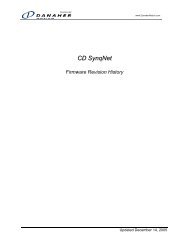
KOLLMORGEN Version 1 -11/07 Sales and Services<br />
Appendix E SALES AND SERVICES<br />
We are committed to quality customer service. In order to serve in the most<br />
effective way, please contact your local sales representative for assistance.<br />
If you are unaware of your local sales representative, please contact us.<br />
Europe<br />
Danaher Motion Customer <strong>Support</strong> Europe<br />
E-mail: sep@danahermotion.net<br />
Phone: +972-3-927-3800<br />
Fax: +972-3-922-8075<br />
www.danahermotion.net<br />
North America<br />
Danaher Motion Customer <strong>Support</strong> North America<br />
E-mail: sep@danahermotion.com<br />
Phone: +972-3-927-3800<br />
Fax: +972-3-927-8075<br />
www.danahermotion.com<br />
SqDC SynqNet DC Drive 37