Design and Construction Standards - Office of Physical Plant ...
Design and Construction Standards - Office of Physical Plant ...
Design and Construction Standards - Office of Physical Plant ...

Create successful ePaper yourself
Turn your PDF publications into a flip-book with our unique Google optimized e-Paper software.
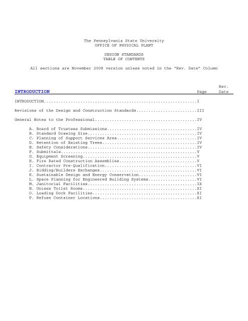
The Pennsylvania State University<br />
OFFICE OF PHYSICAL PLANT<br />
DESIGN STANDARDS<br />
TABLE OF CONTENTS<br />
All sections are November 2008 version unless noted in the “Rev. Date” Column<br />
Rev.<br />
INTRODUCTION Page Date<br />
INTRODUCTION...............................................................I<br />
Revisions <strong>of</strong> the <strong>Design</strong> <strong>and</strong> <strong>Construction</strong> St<strong>and</strong>ards.........................III<br />
General Notes to the Pr<strong>of</strong>essional..........................................IV<br />
A. Board <strong>of</strong> Trustees Submissions.....................................IV<br />
B. St<strong>and</strong>ard Drawing Size.............................................IV<br />
C. Planning <strong>of</strong> Support Services Area.................................IV<br />
D. Retention <strong>of</strong> Existing Trees.......................................IV<br />
E. Safety Considerations.............................................IV<br />
F. Submittals........................................................V<br />
G. Equipment Screening...............................................V<br />
H. Fire Rated <strong>Construction</strong> Assemblies................................V<br />
I. Contractor Pre-Qualification......................................VI<br />
J. Bidding/Builders Exchanges........................................VI<br />
K. Sustainable <strong>Design</strong> <strong>and</strong> Energy Conservation........................VI<br />
L. Space Planning for Engineered Building Systems....................VI<br />
M. Janitorial Facilities.............................................IX<br />
N. Unisex Toilet Rooms...............................................XI<br />
O. Loading Dock Facilities...........................................XI<br />
P. Refuse Container Locations........................................XI
Rev.<br />
DIVISION 00 – PROCUREMENT AND CONTRACTING REQUIREMENTS Page Date<br />
00 00 00 Procurement <strong>and</strong> Contracting Requirements 00-1<br />
.01 ......................................................00-1<br />
Rev.<br />
DIVISION 01 – GENERAL REQUIREMENTS Page Date<br />
01 00 00 General Requirements 01-1<br />
.01 ......................................................01-1<br />
Rev.<br />
DIVISION 02 – EXISTING CONDITIONS Page Date<br />
02 00 00 Existing Conditions 02-1<br />
.01 ......................................................02-1<br />
Rev.<br />
DIVISION 03 – CONCRETE Page Date<br />
03 00 00 Concrete 03-1<br />
03 00 10 Owner General Requirements <strong>and</strong> <strong>Design</strong> Intent.............03-1<br />
.01 General...............................................03-1<br />
.02 Field Testing <strong>of</strong> Concrete.............................03-1<br />
Rev.<br />
DIVISION 04 – MASONRY Page Date<br />
04 00 00 Masonry 04-1<br />
04 00 10 Owner General Requirements <strong>and</strong> <strong>Design</strong> Intent.............04-1<br />
.01 General...............................................04-1<br />
Rev.<br />
DIVISION 05 – METALS Page Date<br />
05 00 00 Metals 05-1<br />
05 00 10 Owner General Requirements <strong>and</strong> <strong>Design</strong> Intent.............05-1<br />
.01 General...............................................05-1
Rev.<br />
DIVISION 07 – MOISTURE PROTECTION Page Date<br />
07 00 00 Moisture Protection 07-1<br />
07 00 10 Owner General Requirements <strong>and</strong> <strong>Design</strong> Intent.............07-1<br />
.01 Ro<strong>of</strong>ing Systems.......................................07-1<br />
07 10 00 Damppro<strong>of</strong>ing <strong>and</strong> Waterpro<strong>of</strong>ing.................................07-1<br />
.01 Waterpro<strong>of</strong>ing—Damppro<strong>of</strong>ing............................07-1<br />
07 20 00 Thermal Protection.............................................07-2<br />
.01 Ro<strong>of</strong> Insulation.......................................07-2<br />
07 60 00 Flashing <strong>and</strong> Sheet Metal.......................................07-2<br />
.01 Flashing..............................................07-2<br />
07 70 00 Ro<strong>of</strong> <strong>and</strong> Wall Specialties <strong>and</strong> Accessories......................07-2<br />
.01 Ro<strong>of</strong> Penetrations.....................................07-2<br />
.02 Ro<strong>of</strong> Drains...........................................07-3<br />
Rev.<br />
DIVISION 08 – DOORS, WINDOWS, GLASS, AND HARDWARE Page Date<br />
08 00 00 Doors, Windows, Glass, <strong>and</strong> Hardware 08-1<br />
08 10 00 Doors <strong>and</strong> Frames 08-1<br />
.01 Exterior Door Frames..................................08-1<br />
.02 Exterior Doors........................................08-1<br />
.03 Interior Doors - Wood.................................08-1<br />
08 50 00 Windows 08-2<br />
.01 Windows...............................................08-2<br />
08 70 00 Hardware 08-3<br />
.01 Finish Hardware Requirements..........................08-3<br />
08 80 00 Glazing 08-7<br />
.01 Glass <strong>and</strong> Glazing.....................................08-7
Rev.<br />
DIVISION 09 – FINISHES Page Date<br />
09 00 00 Finishes 09-1<br />
09 00 10 Owner General Requirements <strong>and</strong> <strong>Design</strong> Intent 09-1<br />
.01 Schedule <strong>of</strong> Finishes 09-1<br />
09 50 00 Ceilings 09-2<br />
.01 Ceilings, Suspended Acoustic..........................09-2<br />
09 90 00 Painting <strong>and</strong> Coating 09-2<br />
.01 Paint.................................................09-2<br />
.02 University Mechanical Color code......................09-3<br />
.01 Door Lettering........................................09-3<br />
Rev.<br />
DIVISION 10 – SPECIALTIES Page Date<br />
10 00 00 Specialties 10-1<br />
10 00 10 Owner General Requirements <strong>and</strong> <strong>Design</strong> Intent.............10-1<br />
.01 Electric Water Coolers................................10-1<br />
10 10 00 Information Specialties 10-1<br />
10 13 00 Directories.................................................10-1<br />
10 14 00 Signage.....................................................10-1<br />
10 20 00 Interior Specialties 10-2<br />
.01 Toilet Room Partitions................................10-2<br />
10 28 13 Toilet Accessories..........................................10-2<br />
.01 Toilet Room Accessories...............................10-2<br />
10 40 00 Safety Specialties 10-3<br />
.01 Fire-Fighting Equipment...............................10-3<br />
10 50 00 Storage Specialties 10-3<br />
.01 Coat <strong>and</strong> Hat Racks....................................10-3
Rev.<br />
DIVISION 11 – EQUIPMENT Page Date<br />
11 00 00 Equipment 11-1<br />
11 10 00 Vehicle <strong>and</strong> Pedestrian Equipment 11-1<br />
11 13 00 Loading Dock Facilities.....................................11-1<br />
11 20 00 Commercial Equipment 11-1<br />
11 24 00 Maintenance Equipment.......................................11-1<br />
.01 Floor <strong>and</strong> Wall Cleaning Equipment.....................11-1<br />
11 50 00 Educational <strong>and</strong> Scientific Equipment 11-1<br />
11 53 13 Laboratory Fume Hoods....................................11-1<br />
.01 General Purpose Constant Volume Fume Hoods............11-1<br />
.02 Auxiliary Air Hoods...................................11-4<br />
.03 Isotope Hoods.........................................11-4<br />
.04 Perchloric Acid Hoods.................................11-5<br />
.05 Fume Hood Testing.....................................11-6<br />
.06 Hood Adjustment <strong>and</strong> Balancing.........................11-8<br />
.07 Hood Maintenance Instructions.........................11-9<br />
.08 Manufacturer’s Recommended Safety Procedures..........11-9<br />
.09 Differential Pressure Switch..........................11-10<br />
Rev.<br />
DIVISION 12 – FURNISHINGS Page Date<br />
12 00 00 Furnishings 12-1<br />
12 20 00 Window Treatments 12-1<br />
12 21 00 Window Blinds...............................................12-1<br />
12 50 00 Furniture 12-1<br />
12 52 00 Seating.....................................................12-1<br />
.01 Fixed Seating.........................................12-1<br />
.02 Movable Seating.......................................12-5<br />
12 56 00 Institutional Furniture 12-6<br />
.01 Movable Instructor’s Table............................12-6<br />
Rev.
DIVISION 13 – SPECIAL CONSTRUCTION Page Date<br />
13 00 00 Special <strong>Construction</strong> 13-1<br />
13 20 00 Special Purpose Rooms 13-1<br />
.01 Special <strong>Construction</strong>-Classroom <strong>Design</strong>s................13-1<br />
13 20 10 Classroom <strong>Design</strong>.........................................13-1<br />
.01 General...............................................13-1<br />
13 20 15 Bookstore <strong>Design</strong>.........................................13-1<br />
.01 General...............................................13-1<br />
.02 Common Areas..........................................13-2<br />
.03 Storage <strong>and</strong> <strong>Office</strong> Area...............................13-2<br />
.04 Windows...............................................13-2<br />
.05 Columns...............................................13-2<br />
.06 Floors................................................13-2<br />
.07 Floor Coverings.......................................13-2<br />
.08 Entrance Mats <strong>and</strong>/or Grilles..........................13-3<br />
.09 Drains................................................13-3<br />
.10 Loading Docks.........................................13-3<br />
.11 Ceiling Heights.......................................13-3<br />
.12 Ceilings..............................................13-3<br />
.13 Lighting..............................................13-4<br />
.14 Electrical............................................13-4<br />
.15 Vents, Intakes <strong>and</strong> Exhausts...........................13-5<br />
.16 Controls..............................................13-5<br />
.17 Telephone <strong>and</strong> Computer Lines..........................13-6<br />
.18 Paint <strong>and</strong> Colors......................................13-6<br />
.19 Miscellaneous.........................................13-7<br />
13 21 00 Radioisotope Laboratory <strong>Design</strong> 13-8<br />
.01 General...............................................13-8<br />
.02 Floors................................................13-8<br />
.03 Eating Area...........................................13-8<br />
.04 Sinks.................................................13-9<br />
.05 Fume Hoods............................................13-9<br />
.06 Animal Rooms..........................................13-10<br />
.07 Miscellaneous.........................................13-10
Rev.<br />
DIVISION 14 – CONVEYING EQUIPMENT Page Date<br />
14 00 00 Conveying Equipment 14-1<br />
14 20 00 Elevators 14-1<br />
.01 General...............................................14-1<br />
.02 Machine Room..........................................14-2<br />
.03 Controls..............................................14-3<br />
.04 Elevator Car..........................................14-6<br />
.05 Signal Fixtures.......................................14-9<br />
.06 Pit & Shaft...........................................14-11<br />
.07 Guarantee <strong>and</strong> Warranties..............................14-12<br />
.08 permits, Testing, <strong>and</strong> Inspections.....................14-12<br />
.09 Maintenance <strong>and</strong> Instruction Material..................14-12<br />
.10 Hydraulic Oil.........................................14-13<br />
Rev.<br />
DIVISION 21 – FIRE SUPPRESSION Page Date<br />
21 00 00 Fire Suppression 21-1<br />
21 00 10 Owner General Requirements <strong>and</strong> <strong>Design</strong> Intent.............21-1<br />
.01 General...............................................21-1<br />
.02 <strong>Design</strong>................................................21-1<br />
.03 Submittals <strong>and</strong> Approvals..............................21-1<br />
.04 Hydrant Tests.........................................21-2<br />
.05 Utilities.............................................21-2<br />
.06 Mechanical Rooms......................................21-2<br />
.07 Janitor Rooms.........................................21-2<br />
21 01 00 Operation <strong>and</strong> Maintenance <strong>of</strong> Fire Suppression...............21-2<br />
21 05 00 Common Work Results for Fire Suppression....................21-3<br />
21 05 01 Fire Suppression General Requirements....................21-3<br />
.01 Painting..............................................21-3<br />
.02 Access Panels.........................................21-3<br />
.03 Motors <strong>and</strong> Drives.....................................21-3<br />
.04 Pressure Gages <strong>and</strong> Thermometers.......................21-4<br />
.05 Pipe Hangers <strong>and</strong> Supports.............................21-5<br />
.06 Sound <strong>and</strong> Vibration Control...........................21-5<br />
.07 Mechanical Identification.............................21-6<br />
21 07 00 Fire Suppression Systems Insulation.........................21-6<br />
.01 Insulation............................................21-6<br />
21 09 00 Instrumentation <strong>and</strong> Control for Fire-Suppression Systems....21-6<br />
.01 Building Fire Alarm Panel.............................21-6
Rev.<br />
DIVISION 21 – FIRE SUPPRESSION Page Date<br />
(Continued)<br />
21 10 00 Water-Based Fire-Suppression Systems 21-6<br />
21 11 00 Facility Fire-Suppression Water-Service Piping..............21-6<br />
.01 Piping................................................21-6<br />
.04 Automatic Source <strong>and</strong> Siamese Connections..............21-8<br />
.05 Pressure-Reducing Valves..............................21-8<br />
.06 Piping (Inside Building)..............................21-8<br />
.07 Valves................................................21-9<br />
21 12 00 Fire-Suppression St<strong>and</strong>pipes.................................21-9<br />
.01 St<strong>and</strong>pipe Systems.....................................21-9<br />
.02 Combination Systems...................................21-10<br />
21 13 00 Fire-Suppression Sprinkler Systems..........................21-10<br />
.01 Sprinklers............................................21-10<br />
Rev.<br />
DIVISION 22 – PLUMBING Page Date<br />
22 00 00 Plumbing 22-1<br />
22 00 10 Owner General Requirements <strong>and</strong> <strong>Design</strong> Intent.............22-1<br />
.01 Utilities.............................................22-1<br />
.02 Mechanical Rooms......................................22-1<br />
.03 Janitor Rooms.........................................22-1<br />
.04 Laboratory Equipment..................................22-1<br />
22 01 00 Operation <strong>and</strong> Maintenance <strong>of</strong> Plumbing.......................22-1<br />
22 05 00 Common Work Results for Plumbing............................22-2<br />
22 05 01 Plumbing General Requirements............................22-2<br />
.01 Painting..............................................22-2<br />
.02 Access Panels.........................................22-2<br />
.03 Piping................................................22-2<br />
.04 Pipe Specialties......................................22-4<br />
.05 Piping Systems Disinfection...........................22-5<br />
.06 Piping Systems Testing................................22-5<br />
.08 Pressure Gages <strong>and</strong> Thermometers.......................22-5<br />
.09 Valves................................................22-6<br />
.10 Pipe Hangers <strong>and</strong> Supports.............................22-7<br />
.11 Sound <strong>and</strong> Vibration Control...........................22-8<br />
.12 Mechanical Identification.............................22-8<br />
22 07 00 Plumbing Insulation.........................................22-8<br />
.01 Insulation............................................22-8<br />
22 10 00 Plumbing Piping <strong>and</strong> Pumps 22-10<br />
22 11 00 Facility Water Distribution.................................22-10<br />
.01 Plumbing Piping.......................................22-10<br />
.02 Plumbing Specialties..................................22-12<br />
.04 Pumps.................................................22-13<br />
22 12 00 Facility Potable-Water Storage Tanks........................22-13<br />
.01 Storage Tanks.........................................22-13
Rev.<br />
DIVISION 22 – PLUMBING Page Date<br />
(Continued)<br />
22 30 00 Plumbing Equipment 22-13<br />
.01 Domestic Water Heaters................................22-13<br />
22 31 00 Domestic Water S<strong>of</strong>teners....................................22-14<br />
.01 Water Conditioners....................................22-14<br />
22 32 00 Domestic Water Filtration Equipment.........................22-15<br />
.01 Water Filtration Devices..............................22-15<br />
22 40 00 Plumbing Fixtures 22-15<br />
.01 Plumbing Fixtures.....................................22-15<br />
22 47 00 Drinking Fountains <strong>and</strong> Water Coolers........................22-18<br />
.01 Drinking Water Cooling Systems........................22-18<br />
22 60 00 Gas & Vacuum Systems for Laboratory <strong>and</strong> Healthcare Facilities 22-19<br />
22 61 00 Compressed-Air Systems for Laboratory <strong>and</strong> Healthcare Facilities ...22-19<br />
.01 Compressed Air Systems................................22-19<br />
22 62 00 Vacuum Systems for Laboratory <strong>and</strong> Healthcare Facilities.....22-19<br />
.01 Vacuum Systems........................................22-19<br />
22 67 00 Processed Water Systems for Laboratory <strong>and</strong> Healthcare Facilities ..22-19<br />
.01 High Purity Water Systems.............................22-19<br />
Rev.<br />
DIVISION 23 – HEATING, VENTILATING, AND AIR-CONDITIONING (HVAC) Page Date<br />
23 00 00 Heating, Ventilating, <strong>and</strong> Air-Conditioning (HVAC) 23-1<br />
23 00 01 Owner General Requirements <strong>and</strong> <strong>Design</strong> Intent.............23-1<br />
.01 Summary <strong>of</strong> <strong>Design</strong> Intent..............................23-1<br />
.02 Related Documents.....................................23-2<br />
.03 Definitions...........................................23-3<br />
.04 Submittals............................................23-3<br />
.05 St<strong>and</strong>ard <strong>of</strong> Quality/Quality Assurance.................23-4<br />
.06 Coordination <strong>and</strong> Space Planning.......................23-4<br />
23 00 10 Systems Selection <strong>and</strong> Application........................23-5<br />
.01 General...............................................23-5<br />
.02 <strong>Design</strong> Conditions.....................................23-6<br />
.03 General Pressure Relationship <strong>and</strong> Ventilation<br />
Requirements for Certain Areas........................23-7<br />
.04 St<strong>and</strong>by Equipment for Critical Areas..................23-8<br />
.05 Emergency Shutdown....................................23-8<br />
.06 Central Heating <strong>and</strong> Cooling <strong>Plant</strong>.....................23-8<br />
.07 Zoning................................................23-10<br />
.08 Water Systems.........................................23-10<br />
.09 All-Air Systems (General).............................23-10<br />
.10 Computer Room Air Conditioning Systems................23-11<br />
.11 Micro <strong>and</strong> Personal computer Lab Air Conditioning......23-12<br />
23 01 00 Operation <strong>and</strong> Maintenance <strong>of</strong> HVAC Systems...................23-12<br />
.01 General...............................................23-12<br />
.02 Maintenance Manuals...................................23-13<br />
.03 Tour/Instruction/Demonstration........................23-14<br />
.04 Start-Up..............................................23-15<br />
.05 Warranties............................................23-16
Rev.<br />
DIVISION 23 – HEATING, VENTILATING, AND AIR-CONDITIONING (HVAC) Page Date<br />
(Continued)<br />
23 05 00 Common Work Results for HVAC................................23-16<br />
23 05 01 Mechanical General Requirements..........................23-16<br />
.01 Motors <strong>and</strong> Drives.....................................23-16<br />
.02 Pressure Gauges <strong>and</strong> Thermometers......................23-18<br />
.03 Valves................................................23-18<br />
.04 Pipe Hangers <strong>and</strong> Supports.............................23-19<br />
.05 Sound <strong>and</strong> Vibration Control...........................23-20<br />
.06 Piping Systems Testing................................23-23<br />
.08 Access Panels.........................................23-28<br />
23 05 93 Testing, Adjusting, <strong>and</strong> Balancing for HVAC...............23-29<br />
.01 Testing <strong>and</strong> Balancing.................................23-29<br />
23 07 00 HVAC Insulation.............................................23-31<br />
.01 Insulation............................................23-31<br />
23 09 00 Instrumentation <strong>and</strong> Control for HVAC........................23-33<br />
.01 General...............................................23-33<br />
23 20 00 HVAC Piping <strong>and</strong> Pumps 23-33<br />
23 21 00 Hydronic Piping <strong>and</strong> Pumps...................................23-33<br />
.01 Hydronic Systems (General)............................23-33<br />
23 21 13 Hydronic Piping..........................................23-34<br />
.01 Piping................................................23-34<br />
.02 Hot Water, Chilled Water, Vent Piping.................23-37<br />
.03 Hydronic Specialties..................................23-37<br />
.04 Cold Water Make-up Piping.............................23-38<br />
.05 Gauge Piping..........................................23-38<br />
.06 Cooling Coil Condensate Drain Piping..................23-39<br />
.07 Blowdown Piping (Boiler)..............................23-39<br />
.08 Ground-coupled Heat Pump Well Field Systems...........23-39<br />
23 21 23 Hydronic Pumps...........................................23-40<br />
.01 Pumps.................................................23-40<br />
23 22 00 Steam <strong>and</strong> Condensate Piping <strong>and</strong> Pumps.......................23-41<br />
.01 Steam Piping (In Building)............................23-41<br />
.02 Steam Condensate Return Piping (In Building)..........23-42<br />
.03 Steam <strong>and</strong> Steam Condensate Specialties................23-42<br />
23 23 00 Refrigerant Piping..........................................23-44<br />
.01 Refrigeration (General)...............................23-44<br />
.02 Refrigerant Specialties...............................23-44<br />
.03 Refrigerant Piping....................................23-44<br />
23 25 00 HVAC Water Treatment........................................23-45<br />
.01 Water Treatment.......................................23-45<br />
.02 Closed Systems Water Treatment (Hot & Chilled Water)..23-45<br />
.03 Open Re-circulating Systems Water Treatment<br />
(Cooling Towers)......................................23-46<br />
.04 Steam Boilers Water Treatment.........................23-48<br />
.05 Ethylene Glycol Systems...............................23-50<br />
.06 Side Steam Filters....................................23-51<br />
.07 Water Analysis <strong>and</strong> Testing for Closed Loop Systems....23-54<br />
.08 Water Treatment Control Limits........................23-58
Rev.<br />
DIVISION 23 – HEATING, VENTILATING, AND AIR-CONDITIONING (HVAC) Page Date<br />
(Continued)<br />
23 30 00 HVAC Air Distribution 23-59<br />
23 31 00 HVAC Ducts <strong>and</strong> Casings......................................23-59<br />
.01 Ductwork..............................................23-59<br />
23 33 00 Air Duct Accessories........................................23-60<br />
.01 Fire Dampers..........................................23-60<br />
.02 Sound Attenuators.....................................23-61<br />
23 34 00 HVAC Fans...................................................23-61<br />
.01 Fans..................................................23-61<br />
23 36 00 Air Terminal Units..........................................23-62<br />
.01 VAV Boxes.............................................23-62<br />
23 37 00 Air Outlets <strong>and</strong> Inlets......................................23-62<br />
.01 Air Terminal Devices (Diffusers, Registers, Grilles)..23-62<br />
23 38 00 Ventilation Hoods...........................................23-63<br />
23 38 16 Fume Hoods...............................................23-63<br />
.01 Fume Hood Exhaust Systems.............................23-63<br />
23 40 00 HVAC Air Cleaning Devices 23-63<br />
23 41 00 Particulate Air Filtration..................................23-63<br />
.01 Air Filters...........................................23-63<br />
23 50 00 Central Heating Equipment 23-64<br />
.01 Combustion Safeguards.................................23-64<br />
23 57 00 Heat Exchangers for HVAC....................................23-64<br />
.01 Heat Exchangers.......................................23-64<br />
23 60 00 Central Cooling Equipment 23-65<br />
23 64 00 Packaged Water Chillers.....................................23-65<br />
.01 Water Chillers (General)..............................23-65<br />
23 65 00 Cooling Towers..............................................23-66<br />
.01 Cooling Towers (General)..............................23-66<br />
23 70 00 Central HVAC Equipment 23-67<br />
.01 Air-H<strong>and</strong>ling Equipment (General)......................23-67<br />
.02 Central Station Air-H<strong>and</strong>ling Units....................23-67<br />
.03 Energy Recovery Units.................................23-68<br />
23 80 00 Decentralized HVAC Equipment 23-69<br />
23 81 00 Decentralized Unitary HVAC Equipment........................23-69<br />
.01 Packaged Ro<strong>of</strong>top Equipment............................23-69<br />
.02 Packaged Heat Pumps...................................23-69<br />
.03 Water-Source Heat Pump Systems........................23-69<br />
23 82 00 Convection Heating <strong>and</strong> Cooling Units........................23-72<br />
.01 Air Coils.............................................23-72<br />
.02 Heating Terminal Units (General)......................23-73<br />
.03 Finned Tube Radiation.................................23-73<br />
.04 Fan Coil Units........................................23-73<br />
.05 Unit Ventilators......................................23-73<br />
23 83 00 Radiant Heating Units.......................................23-74<br />
.01 Radiant Heaters.......................................23-74<br />
23 84 00 Humidity Control Equipment..................................23-74<br />
.01 Humidifiers...........................................23-74<br />
.02 Dehumidifiers.........................................23-74
Rev.<br />
DIVISION 26 – ELECTRICAL Page Date<br />
26 00 00 Electrical 26-1<br />
26 00 01 Owner General Requirements <strong>and</strong> <strong>Design</strong> Intent.............26-1<br />
.01 General...............................................26-1<br />
.02 LEED..................................................26-2<br />
.10 Scope (Basis <strong>of</strong> <strong>Design</strong>/Application <strong>of</strong> Systems)........26-2<br />
.20 Definitions...........................................26-4<br />
.30 Submittals............................................26-4<br />
.40 St<strong>and</strong>ard <strong>of</strong> Quality/Quality Assurance (reserved)......26-5<br />
.50 Coordination (reserved)...............................26-5<br />
26 01 00 Operation <strong>and</strong> Maintenance <strong>of</strong> Electrical Systems.............26-5<br />
.01 General...............................................26-5<br />
26 05 00 Common Work Results for Electrical..........................26-5<br />
26 05 10 Electrical Acceptance Testing............................26-5<br />
.01 Electrical Acceptance Testing.........................26-5<br />
.02 System Function Tests.................................26-7<br />
.03 Thermographic Survey..................................26-7<br />
.04 Electromagnetic Field Testing.........................26-8<br />
.05 Voltage Drop Testing..................................26-8<br />
.06 Fire Alarm Testing....................................26-8<br />
26 05 13 Medium-Voltage Cables....................................26-9<br />
.01 Primary Cables........................................26-9<br />
26 05 19 Low-Voltage Electrical Power Conductors <strong>and</strong> Cables.......26-9<br />
.01 Cabling...............................................26-9<br />
26 05 26 Grounding <strong>and</strong> Bonding for Electrical Systems.............26-9<br />
.01 General...............................................26-9<br />
26 05 29 Hangers <strong>and</strong> Supports for Electrical Systems (reserved)...26-10<br />
26 05 33 Raceway <strong>and</strong> Boxes for Electrical Systems.................26-11<br />
.01 General...............................................26-11<br />
26 05 36 Cable Trays for Electrical Systems.......................26-12<br />
.01 Cable Trays...........................................26-12<br />
26 05 43 Underground Ducts <strong>and</strong> Raceways for Electrical Systems....26-12<br />
.01 Underground Ducts.....................................26-12<br />
.02 Manholes <strong>and</strong> Transformer Foundations..................26-12<br />
26 05 48 Vibration <strong>and</strong> Seismic Controls for Electrical Systems....26-14<br />
.01 General...............................................26-14<br />
26 05 53 Identification for Electrical Systems....................26-14<br />
.01 General...............................................26-14<br />
26 05 73 Engineering Power Studies................................26-16<br />
.01 General...............................................26-16<br />
.02 Coordination Study....................................26-17<br />
.03 Fault Current Study...................................26-17<br />
.04 NFPA 70E (Arc Flash Analysis) Study...................26-18<br />
26 09 00 Instrumentation <strong>and</strong> Control for Electrical Systems..........26-20<br />
26 09 23 Lighting Control Devices.................................26-20<br />
.01 General...............................................26-20<br />
26 09 26 Lighting Control Panelboards.............................26-21
Rev.<br />
DIVISION 26 – ELECTRICAL Page Date<br />
(Continued)<br />
26 10 00 Medium-Voltage Electrical Distribution 26-21<br />
26 11 00 Substations.................................................26-21<br />
26 11 16 Secondary Unit Substations...............................26-21<br />
.01 General...............................................26-21<br />
26 12 00 Medium-Voltage Transformers.................................26-21<br />
.01 Distribution Transformers.............................26-21<br />
.02 Grounding.............................................26-22<br />
26 20 00 Low-Voltage Electrical Distribution 26-22<br />
.01 General...............................................26-22<br />
26 22 00 Low-Voltage Transformers....................................26-24<br />
.01 General...............................................26-24<br />
26 23 00 Low-Voltage Switchgear......................................26-26<br />
.01 General...............................................26-26<br />
26 24 00 Switchboards <strong>and</strong> Panelboards................................26-27<br />
26 24 13 Switchboards.............................................26-27<br />
.01 General...............................................26-27<br />
26 24 16 Panelboards..............................................26-27<br />
.01 General...............................................26-27<br />
26 24 19 Motor-Control Centers....................................26-30<br />
.01 General...............................................26-30<br />
26 25 00 Enclosed Bus Assemblies.....................................26-30<br />
.01 General...............................................26-30<br />
26 26 00 Power Distribution Units....................................26-31<br />
.01 General...............................................26-31<br />
26 27 00 Low-Voltage Distribution Equipment..........................26-31<br />
26 27 13 Electricity Metering.....................................26-31<br />
.01 General...............................................26-31<br />
26 27 26 Wiring Devices...........................................26-31<br />
.01 General...............................................26-31<br />
26 28 00 Low-Voltage Circuit Protective Devices......................26-32<br />
26 28 16 Enclosed Switches <strong>and</strong> Circuit Breakers...................26-32<br />
26 29 00 Low-Voltage Controllers.....................................26-33<br />
26 29 23 Variable-Frequency Motor Controllers.....................26-33<br />
26 30 00 Facility Electrical Power Generating <strong>and</strong> Storing Equipment 26-33<br />
.01 Essential (Emergency <strong>and</strong> St<strong>and</strong>by) Power Systems.......26-33<br />
.02 Life Safety Power.....................................26-33<br />
.03 Critical Power........................................26-34<br />
.04 St<strong>and</strong>by Power.........................................26-34<br />
26 32 00 Packaged Generator Assemblies...............................26-35<br />
26 32 13 Engine Generators........................................26-35<br />
.01 General...............................................26-35<br />
26 35 00 Power Filters <strong>and</strong> Conditioners..............................26-36<br />
26 35 33 Power Factor Correction Equipment........................26-36<br />
.01 General...............................................26-36<br />
26 36 00 Transfer Switches...........................................26-36<br />
.01 General...............................................26-36
Rev.<br />
DIVISION 26 – ELECTRICAL Page Date<br />
(Continued)<br />
26 40 00 Electrical <strong>and</strong> Cathodic Protection 26-37<br />
26 41 00 Facility Lighting Protection................................26-37<br />
.01 General...............................................26-37<br />
26 43 00 Surge Protective Devices....................................26-37<br />
26 43 13 Surge Protective Devices for Low-Voltage Electrical<br />
Power Circuits...........................................26-37<br />
.01 General...............................................26-37<br />
26 50 00 Lighting 26-38<br />
26 51 00 Interior Lighting...........................................26-38<br />
.01 Lighting <strong>Design</strong>.......................................26-38<br />
.02 Lamps.................................................26-39<br />
.03 Ballasts..............................................26-39<br />
.04 Luminaires............................................26-40<br />
.05 Installation..........................................26-41<br />
26 52 00 Emergency Lighting..........................................26-41<br />
.01 General...............................................26-41<br />
26 53 00 Exit Signs..................................................26-42<br />
.01 General...............................................26-42<br />
26 56 00 Exterior Signs..............................................26-42<br />
.01 General...............................................26-42<br />
.02 “Site” (Walkway, Roadway, <strong>and</strong> Parking) Lighting<br />
Circuitry.............................................26-42<br />
Rev.<br />
DIVISION 27 – COMMUNICATIONS Page Date<br />
27 00 00 Communications 27-1<br />
27 05 00 Common Work Results for Communications......................27-1<br />
.01 General...............................................27-1<br />
27 05 43 Underground Ducts <strong>and</strong> Raceways for Communications Systems27-1<br />
.01 Underground Conduit...................................27-1<br />
.02 Manholes..............................................27-2<br />
Rev.<br />
DIVISION 28 – ELECTRONIC SAFETY AND SECURITY Page Date<br />
28 00 00 Electronic Safety <strong>and</strong> Security 28-1<br />
28 30 00 Electronic Detection <strong>and</strong> Alarm 28-1<br />
28 31 00 Fire Detection <strong>and</strong> Alarm....................................28-1<br />
.01 Microprocessor-Based Fire Alarm Systems...............28-1<br />
.02 Conventional Fire Alarm Systems.......................28-5
Rev.<br />
DIVISION 31 – EARTHWORK Page Date<br />
31 00 00 Earthwork 31-1<br />
31 01 00 General Requirements <strong>and</strong> Owner Intent.......................31-1<br />
.01 Earth Disturbance Management Guidelines...............31-1<br />
.02 Test Borings..........................................31-4<br />
.03 Inspection <strong>and</strong> Testing................................31-4<br />
.04 Soil Protection Zones.................................31-5<br />
31 10 00 Site Clearing 31-9<br />
.01 Site Clearance........................................31-9<br />
31 20 00 Earth Moving 31-9<br />
.01 Excavation--Backfill..................................31-9<br />
.02 Stockpiling, Furnishing, <strong>and</strong> Placing Topsoil..........31-11<br />
Rev.<br />
DIVISION 32 – EXTERIOR IMPROVEMENTS Page Date<br />
32 00 00 Exterior Improvements 32-1<br />
32 01 00 General Requirements <strong>and</strong> Owner Intent.......................32-1<br />
.01 Inspection <strong>and</strong> Testing................................32-1<br />
32 10 00 Bases, Ballasts, <strong>and</strong> Paving 32-1<br />
.01 Curbs <strong>and</strong> Gutters.....................................32-1<br />
.02 Portl<strong>and</strong> Cement Concrete Paving.......................32-2<br />
.03 Exterior Concrete Steps...............................32-6<br />
.04 Hot-Mix Asphalt Paving................................32-7<br />
.05 Stone Beds............................................32-11<br />
32 90 00 <strong>Plant</strong>ing 32-12<br />
.01 Tree Canopy/Tree Root Protection Zones................32-12<br />
.02 Lawns <strong>and</strong> Grasses.....................................32-17<br />
.03 Trees <strong>and</strong> Shrubs......................................32-27
Rev.<br />
DIVISION 33 – UTILITIES Page Date<br />
33 00 00 Utilities 33-1<br />
33 01 00 General Requirements <strong>and</strong> Owner Intent.......................33-1<br />
.01 General...............................................33-1<br />
.02 Temporary Utility Service.............................33-3<br />
33 10 00 Water Utilities 33-3<br />
.01 Water.................................................33-3<br />
33 20 00 Wells 33-8<br />
33 30 00 Sanitary Sewerage Utilities 33-10<br />
.01 Sanitary Systems......................................33-10<br />
33 40 00 Storm Drainage Utilities 33-12<br />
.01 Stormwater Systems....................................33-12<br />
33 50 00 Fuel Distribution Utilities 33-17<br />
.01 Gas...................................................33-17<br />
33 56 00 Fuel-Storage Tanks..........................................33-19<br />
.01 Underground/Aboveground Storage Tank <strong>Design</strong>...........33-19<br />
.02 Aboveground Storage Tanks.............................33-19<br />
.03 Underground Storage Tanks.............................33-17<br />
33 60 00 Hydronic <strong>and</strong> Steam Energy Utilities 33-21<br />
33 61 00 Hydronic Energy Distribution................................33-21<br />
33 63 00 Steam Energy Distribution...................................33-21<br />
.01 Steam.................................................33-21<br />
.02 Air...................................................33-24<br />
33 70 00 Electrical Utilities 33-25<br />
.01 Electric..............................................33-25<br />
33 80 00 Communications Utilities 33-25<br />
.01 CCS...................................................33-25<br />
.02 Telecommunications....................................33-25
INTRODUCTION<br />
This manual <strong>of</strong> <strong>Design</strong> <strong>and</strong> <strong>Construction</strong> St<strong>and</strong>ards has been prepared by the<br />
University to guide Architects <strong>and</strong> Engineers, hereinafter referred to as the<br />
Pr<strong>of</strong>essional, commissioned to design buildings <strong>and</strong> other facilities for The<br />
Pennsylvania State University. The information contained herein applies to<br />
the University Park Campus; the Commonwealth College Campuses; Penn State<br />
Erie, The Behrend College; Capital College; The Milton S. Hershey Medical<br />
Center; <strong>and</strong> all other locations.<br />
These st<strong>and</strong>ards <strong>and</strong> guidelines are the result <strong>of</strong> considerable experience in<br />
the design, construction, operation <strong>and</strong> maintenance <strong>of</strong> a substantial number<br />
<strong>of</strong> physical facilities. It is intended that the material included in this<br />
manual shall be applied in the preparation <strong>of</strong> documents for the design <strong>and</strong><br />
construction <strong>of</strong> new buildings <strong>and</strong> renovations to existing physical<br />
facilities. If the Pr<strong>of</strong>essional believes that a specific situation requires<br />
a deviation from the st<strong>and</strong>ards contained in this manual, he should discuss<br />
such a deviation with the University Project Manager, <strong>and</strong> request in writing<br />
that a special exception be approved.<br />
All buildings <strong>and</strong> other projects for the University shall be designed as<br />
quality institutional facilities with components specified to provide maximum<br />
life-cycle usefulness. The University establishes the total project budget,<br />
including the maximum fund available for construction. The Pr<strong>of</strong>essional is<br />
charged to monitor program requirements <strong>and</strong> cost estimates to assure that the<br />
project is designed within available funding, <strong>and</strong> that it does not deviate<br />
from the quality st<strong>and</strong>ards established in this manual.<br />
The Pr<strong>of</strong>essional shall design the project in compliance with all applicable<br />
Federal, State <strong>and</strong> Local codes, ordinances, laws <strong>and</strong> other regulations which<br />
have jurisdiction over the nature <strong>of</strong> the construction. If any <strong>of</strong> the above<br />
are at variance with the material in this manual, the most dem<strong>and</strong>ing<br />
requirements shall be observed.<br />
In addition to the above mentioned codes, for University owned buildings, the<br />
University uses the most current editions <strong>of</strong> the following codes <strong>and</strong><br />
st<strong>and</strong>ards as design criteria:<br />
Applicable codes <strong>of</strong> the PA Uniform <strong>Construction</strong> Code (UCC)<br />
ASME Codes<br />
ANSI B31.1 Code<br />
FM Global St<strong>and</strong>ards<br />
The University has a commitment to environmental stewardship <strong>and</strong> requires the<br />
maximum possible use <strong>of</strong> sustainable <strong>and</strong> energy-efficient designs <strong>and</strong><br />
specifications, for architectural, site, utility, structural, mechanical,<br />
electrical, <strong>and</strong> plumbing work. The Pr<strong>of</strong>essional should be aware that all<br />
designs will be reviewed by the University within this context.<br />
The process for complying with zoning or l<strong>and</strong> use regulations shall be<br />
managed by the University.<br />
The Pr<strong>of</strong>essional shall attend all hearings/meetings required for securing<br />
necessary approvals <strong>and</strong> permits.<br />
The Pr<strong>of</strong>essional shall be responsible for completing all the appropriate<br />
planning modules, soil erosion control plans <strong>and</strong> other documents which may be<br />
required.<br />
11/08 I
The Pr<strong>of</strong>essional shall be responsible for obtaining whatever permission<br />
necessary to connect to non-University owned utility lines.<br />
4/89<br />
Rev. 12-14-89<br />
Rev. 8-7-91<br />
Rev. 10-29-93<br />
Rev. 11/98<br />
Rev. 4-23-01<br />
Rev. 4-27-01<br />
Rev. 7-26-01<br />
Rev. 10-17-01<br />
Rev. 2-15-02<br />
Rev. 4-15-05<br />
Rev. 12-21-06<br />
Rev. 2-23-07<br />
11/08 II
REVISIONS OF THE DESIGN AND CONSTRUCTION STANDARDS<br />
Changing technology <strong>and</strong> changes in University requirements will require<br />
continuing revisions <strong>and</strong> updates to the manual. All comments <strong>and</strong> proposed<br />
corrections or revisions should be directed in writing to:<br />
0BKathryn Poissant<br />
1BArchitect <strong>Design</strong> Services<br />
113 <strong>Physical</strong> <strong>Plant</strong> Building<br />
University Park, PA 16802<br />
2BKAP4@nw.opp.psu.edu<br />
After review <strong>and</strong> approval <strong>of</strong> the Committee, the revisions will be made to the<br />
web version <strong>of</strong> the st<strong>and</strong>ards.<br />
All pages <strong>of</strong> revised <strong>and</strong>/or new sections will be dated in the lower left-h<strong>and</strong><br />
corner. The most recent revisions are indicated by a vertical line in the<br />
margin next to the text. Asterisks in the margin indicate locations where<br />
text has been removed.<br />
The revision date will also be recorded in the Date Revised column in the<br />
Table <strong>of</strong> Contents. Each user <strong>of</strong> the manual shall delete obsolete pages <strong>and</strong><br />
insert revised pages as required.<br />
Before starting a project for the University, all Pr<strong>of</strong>essionals shall ensure<br />
that their copy <strong>of</strong> the <strong>Design</strong> <strong>and</strong> <strong>Construction</strong> St<strong>and</strong>ards is up to date.<br />
10/08 III
A. UBoard <strong>of</strong> Trustees Submissions<br />
10/08 IV<br />
GENERAL NOTES TO THE PROFESSIONAL<br />
1. The Pr<strong>of</strong>essional shall be responsible for the preparation <strong>of</strong> graphic<br />
material to be presented to the University Board <strong>of</strong> Trustees when their<br />
approval is required for a project. Refer to the "Board <strong>of</strong> Trustees (BOT)<br />
Submission Requirements" on Penn State <strong>Design</strong> & <strong>Construction</strong> web page<br />
for specific instructions on the requirements for information<br />
<strong>and</strong> graphics, based on project cost <strong>and</strong> type.<br />
B. USt<strong>and</strong>ard Drawing Size<br />
1. Drawings shall be prepared on st<strong>and</strong>ard sheet sizes 24 inches by 36 inches<br />
or on sheets 30 inches by 42 inches. Use <strong>of</strong> any other sheet size requires<br />
the prior approval by the University<br />
Project Manager.<br />
C. UPlanning <strong>of</strong> Support Services Area<br />
1. During the planning <strong>and</strong> design stages <strong>of</strong> the project, the Pr<strong>of</strong>essional<br />
shall consider the need to provide certain support service areas that may<br />
be required for a particular project but not necessarily identified in the<br />
program. The need for the following types <strong>of</strong> areas shall be reviewed, <strong>and</strong><br />
where appropriate, included as part <strong>of</strong> the project:<br />
• Public Telephone Location<br />
• Vending Machine Location<br />
• Employee Lounge<br />
• Central Mail Room<br />
• Central Copy Area<br />
• Loading Dock<br />
D. URetention <strong>of</strong> Existing Trees<br />
1. To encourage the retention <strong>of</strong> mature trees which are one <strong>of</strong> the<br />
University's prime assets, <strong>and</strong> to correct the current slow depletion <strong>of</strong><br />
the campus tree canopy, the Pr<strong>of</strong>essional shall site the building to<br />
minimize the loss <strong>of</strong> <strong>and</strong> impact on mature trees.<br />
2. The l<strong>and</strong>scape plan for the project shall be integrated with the<br />
surrounding l<strong>and</strong>scape design <strong>and</strong> it shall include trees.<br />
E. USafety Considerations<br />
1. Runways <strong>and</strong> ramps should be installed in all buildings where bulk supplies<br />
are h<strong>and</strong>led. Ramps should have a surface providing traction.<br />
2. All glass <strong>and</strong> glazed doors used at entrances, stairwells, etc., shall have<br />
adequate push plates or bars <strong>and</strong> proper glass as required by applicable<br />
building codes or regulations.
3. All windows in buildings (above ground floor) must be <strong>of</strong> the type which<br />
can be washed on both sides from the inside <strong>of</strong> the building. Where<br />
construction is such that this type <strong>of</strong> window cannot be installed, there<br />
shall be safety belt anchors placed at the outside <strong>of</strong> the windows for<br />
fastening safety belts <strong>and</strong> an outside ledge for st<strong>and</strong>ing not less than 12"<br />
wide. Safety belt anchors installed outside shall be a st<strong>and</strong>ard approved<br />
type. They shall not be the expansion bolt type.<br />
4. On all windows where the stool <strong>of</strong> the window is less than two feet from<br />
the floor, there shall be bars or other approved means provided to<br />
eliminate the possibility <strong>of</strong> falls through the windows. Casement windows<br />
or other outward projecting sash will not be used at the ground floor.<br />
5. A non-slip nosing shall be installed on all interior stairs. Nosings with<br />
grooves or other depressions tending to form trip hazards shall not be<br />
permitted. (UCarborundumU or UsimilarU UabrasivesU are not permitted.)<br />
6. All outside steps must be adequately lighted. Treads <strong>and</strong> l<strong>and</strong>ings should<br />
have positive drainage away from the building.<br />
7. Suitable railings <strong>and</strong> guards shall be provided at all places such as<br />
stairwells, outside steps, bridges, loading ramps, etc. where persons are<br />
exposed to the possibility <strong>of</strong> falls from one level to another.<br />
8. All inside lighting fixtures must be placed so relamping can be<br />
accomplished Uwith minimum effort <strong>and</strong> hazardU.<br />
9. Chemical <strong>and</strong> flammable liquid storage <strong>and</strong> usage areas will be ventilated<br />
sufficiently to remove all fumes <strong>and</strong> shall be constructed in accord with<br />
all applicable codes <strong>and</strong> University requirements.<br />
10. For the University piping color code <strong>and</strong> the usual painting called for<br />
under the mechanical trades, the University uses a "Color Code" for the<br />
identification <strong>of</strong> certain equipment <strong>and</strong> piping. See Division 15A.<br />
F. USubmittals<br />
1. To assist the Contractor(s) in following through on all the various<br />
submittals that will be required <strong>of</strong> them, the Pr<strong>of</strong>essional shall include<br />
in the contract documents, complete with the Specification<br />
section/paragraph reference, a table indicating all the shop drawings,<br />
catalog data, manufacturer's operating instructions, maintenance<br />
instructions, certificates, warranties, guarantees <strong>and</strong> any other pertinent<br />
operating <strong>and</strong> maintenance data.<br />
G. UEquipment Screening<br />
1. All exposed exterior mechanical <strong>and</strong> electrical equipment is to be screened<br />
from view. The screening method to be employed will be determined on an<br />
individual project basis.<br />
H. UFire Rated <strong>Construction</strong> Assemblies<br />
1. All construction assemblies which require a specific fire rating; i.e., 1hour,<br />
2-hour, etc., shall be so designated on the construction drawings.<br />
In addition, the governing agency or applicable code, edition, <strong>and</strong> date<br />
shall also be indicated. The purpose <strong>of</strong> this is so that the University<br />
can maintain the required ratings when future revisions are made.<br />
10/08 V
I. UContractor Pre-Qualification<br />
1. Refer to web site for contractor pre-qualification information.<br />
J. UBidding/Builders Exchanges<br />
1. A complete set <strong>of</strong> bid documents is also to be sent to the agencies listed<br />
in "Section A, Notice to Bidders" located on the UPenn State <strong>Design</strong> &<br />
<strong>Construction</strong> St<strong>and</strong>ards PageU,<br />
.<br />
K. USustainable <strong>Design</strong> <strong>and</strong> Energy Conservation<br />
1. All new <strong>and</strong> renewed facilities shall be Leadership in Energy <strong>and</strong><br />
Environmental <strong>Design</strong> (LEED) certified.<br />
2. LEED Certification shall follow the “PSU Policy based on LEED for New<br />
<strong>Construction</strong> <strong>and</strong> Major Renovations Version 2.2” found at<br />
.<br />
3. All facilities shall achieve a minimum <strong>of</strong> at least 30% energy savings over<br />
the latest version <strong>of</strong> the ASHRAE 90.1 st<strong>and</strong>ard. Documentation <strong>of</strong><br />
compliance shall be according to the Energy Cost Budget Method as<br />
prescribed in ASHRAE 90.1 utilizing a whole building energy simulation.<br />
L. USpace Planning for Engineered Building Systems<br />
1. General<br />
a. Always design with maintenance in mind. Maintenance <strong>and</strong> housekeeping<br />
are daily activities in every campus building. The University expects<br />
these activities to be carried out in a manner that students <strong>and</strong><br />
faculty are not aware <strong>of</strong> the effort. Similarly, buildings <strong>and</strong><br />
improvements are needed that lend themselves to cost effective<br />
utilization <strong>of</strong> manpower in a discrete manner.<br />
b. <strong>Design</strong> team shall fully coordinate all requirements to ensure easily<br />
accessible, unobstructed, safe, generous, sufficient space for<br />
mechanical <strong>and</strong> electrical equipment rooms <strong>and</strong> general maintenance<br />
storage when developing the building floor plans.<br />
1) <strong>Design</strong>ated mechanical/electrical equipment rooms, mezzanines <strong>and</strong><br />
platforms shall have at least the minimum headroom/ceiling height<br />
required by building code for Uoccupiable spacesU. Crawlspaces<br />
(either basement or attic) are not acceptable plant equipment<br />
rooms.<br />
c. <strong>Design</strong> for Safety: The plant <strong>and</strong> systems must be located <strong>and</strong> arranged<br />
to permit adequate means <strong>of</strong> escape <strong>and</strong> access for maintenance without<br />
exposing the maintenance staff to undue safety risk.<br />
d. <strong>Design</strong> for Cost Effective Replacement: All mechanical <strong>and</strong> electrical<br />
rooms shall be located, have adequate floor area <strong>and</strong> door sizes <strong>and</strong> be<br />
internally arranged with entirely clear aisles to permit the removal<br />
<strong>and</strong> replacement <strong>of</strong> the largest piece <strong>of</strong> equipment from the space to the<br />
building exterior without dismantling other equipment or permanent<br />
building general construction.<br />
1) Primary aisles intended to be kept clear in perpetuity for<br />
equipment replacement shall be clearly indicated on construction<br />
10/08 VI
drawings <strong>and</strong> with painted boundaries on final floor finishes in<br />
mechanical/electrical rooms.<br />
2) Building design shall not require a crane to replace common systems<br />
components such as pumps, motors, fan wheels, coils, compressors,<br />
transformers, electrical gear, motor starters, etc.<br />
3) In buildings with elevators, elevator with sufficient capacity<br />
shall extend to all levels, including ro<strong>of</strong>, with<br />
mechanical/electrical equipment having any replaceable component<br />
that cannot be safely transported down stairs or ship ladders.<br />
4) Include ro<strong>of</strong> access hatches, hinged or easily removeable louvers,<br />
knockout panels or similar other architectural features as<br />
necessary for major equipment replacement that cannot be otherwise<br />
h<strong>and</strong>led through routine means.<br />
5) Coordinate between disciplines to provide adequate structural<br />
strength in all areas over which heavy equipment is required to be<br />
rolled in <strong>and</strong> out <strong>of</strong> the building.<br />
e. Allow adequate dedicated spaces for building system control panels:<br />
local Building Automation Systems (BAS) operator workstation,<br />
associated BAS network controllers/panels, security/access control<br />
panels, fire alarm control panels, lighting control panels. These<br />
types <strong>of</strong> building operation control panels shall not be placed in<br />
spaces shared <strong>and</strong>/or the access controlled by the occupants or<br />
departments other than OPP, including but limited to the following:<br />
2. Mechanical<br />
1) Departmental work or storage spaces<br />
2) TNS server room, work or storage spaces<br />
3) Janitorial/Housekeeping<br />
a. Mechanical rooms shall be sufficiently sized <strong>and</strong> equipment arranged to<br />
accommodate proper, efficient <strong>and</strong> safe access conditions for routine<br />
maintenance <strong>and</strong> replacement.<br />
1) There shall be enough clear space around equipment to do such<br />
things as change filters, pull coils, removal <strong>of</strong> fans, shafts,<br />
motors, bearing assemblies, etc. without moving other equipment or<br />
building general construction.<br />
2) Allow at least three feet between all service sides <strong>of</strong> AHU’s <strong>and</strong><br />
other large equipment <strong>and</strong> obstructions.<br />
3) Minimize the need to do maintenance from ladders. Provide<br />
permanent ship ladders, equipment platforms, safety rails, anchor<br />
points <strong>and</strong> lanyards, etc as required to safely access overhead<br />
equipment.<br />
4) Provide overhead structural steel with portable chain hoists to<br />
lift <strong>and</strong> rig heavy motors, compressors, fans, etc to means <strong>of</strong><br />
transporting out <strong>of</strong> building.<br />
5) Consider <strong>and</strong> plan for general maintenance storage requirements in<br />
mechanical rooms.<br />
6) Avoid tripping hazards. Arrange equipment <strong>and</strong> provide sufficient<br />
floor drains to avoid running pipes across walking paths on floors.<br />
7) Refer to Section 230000 for appropriate environmental conditions in<br />
these spaces.<br />
10/08 VII
. To the greatest extent possible, mechanical equipment shall be located<br />
indoors to maximize useful service life <strong>and</strong> for safety <strong>and</strong> ease <strong>of</strong><br />
maintenance staff, particularly during adverse weather conditions.<br />
c. No outdoor/ro<strong>of</strong>top primary air h<strong>and</strong>ling equipment is allowed without<br />
written permission from the <strong>Office</strong> <strong>of</strong> <strong>Physical</strong> <strong>Plant</strong>, Engineering<br />
Services.<br />
1) Exceptions:<br />
a) Unitary DX units with no hydronic or steam coils subject to<br />
freezing.<br />
b) Renovations to existing facilities in which it is otherwise<br />
not practical or feasible to provide adequate indoor<br />
mechanical space.<br />
10/08 VIII<br />
i. Where otherwise unavoidable, hydronic systems subject to<br />
freezing conditions shall be protected with separate<br />
piping loops with antifreeze solution, heat exchangers,<br />
pumps, expansion tanks, as required to prevent freezing<br />
in the event <strong>of</strong> extended electrical power outage <strong>and</strong> to<br />
minimize <strong>and</strong> isolate portions <strong>of</strong> systems requiring<br />
antifreeze from the main hot <strong>and</strong> chilled water loops.<br />
ii. Steam traps <strong>and</strong> drip legs shall be located below the<br />
thermal insulation envelope <strong>of</strong> the ro<strong>of</strong> assembly.<br />
iii. Alternatively, all sections <strong>of</strong> piping exposed to<br />
freezing conditions shall be completely electrically<br />
heat traced on circuits on normal/emergency st<strong>and</strong>by<br />
power.<br />
iv. Outdoor/ro<strong>of</strong>top equipment shall include stairs/ladders,<br />
raised platforms, gratings, <strong>and</strong> h<strong>and</strong>rails for adequate<br />
access to all main components.<br />
v. Provide adequate safety <strong>and</strong> visual screening.<br />
d. Locate primary air h<strong>and</strong>ling equipment <strong>and</strong> all pumps, heat exchangers in<br />
dedicated mechanical rooms, never above ceilings.<br />
e. Acoustically treat rooms <strong>and</strong>/or equipment to contain equipment noise.<br />
f. Include stairway or ships ladder to any equipment on the ro<strong>of</strong>.<br />
Review with OPP <strong>and</strong> obtain approval if vertical ladders are only<br />
practical solution for existing facilities.<br />
3. Electrical<br />
a. Service entrance electrical room:<br />
1) A dedicated shall be located on the perimeter <strong>of</strong> the building<br />
immediately adjacent to the pad-mount transformer.<br />
2) The electrical room shall have a physical separation from the<br />
other spaces in the building (including mechanical equipment<br />
rooms) with a minimum fire resistance rating <strong>of</strong> one hour (review<br />
code for stricter requirements).
3) Heating <strong>and</strong> ventilation <strong>of</strong> the main electrical room shall be<br />
dedicated to that room, <strong>and</strong> ventilation air shall not be<br />
transferred from adjacent spaces. Consider how air flow through<br />
the space will best cool any heat producing equipment.<br />
4) Size to allow for future growth <strong>of</strong> the service entrance equipment<br />
<strong>of</strong> at least 25% <strong>of</strong> design requirements. There shall be adequate<br />
initial space <strong>and</strong> “future” space to allow the installation <strong>of</strong><br />
additional sections equal in size to the switchgear required for<br />
this project.<br />
b. If the service requires switchgear, it shall be located in the center<br />
<strong>of</strong> the room <strong>and</strong> shall allow for working clearance on ALL four sides<br />
<strong>of</strong> the equipment.<br />
c. Electrical distribution panel rooms/closets shall be dedicated<br />
spaces, with room for additional panelboard sections in the future.<br />
Transformers shall be floor mounted.<br />
d. Engine generators, when required, shall be placed on grade at the<br />
exterior or within the building. At no time will this equipment be<br />
installed above grade level or on a ro<strong>of</strong>. Give consideration as to<br />
the survivability <strong>of</strong> this equipment; do not locate adjacent to the<br />
service transformer or below grade where it may be flooded.<br />
M. UJanitorial Facilities<br />
1. Janitorial facilities will vary according to size, type, <strong>and</strong> use <strong>of</strong> the<br />
building, but in general 200 sq. ft. <strong>of</strong> useable custodial space shall be<br />
provided for each 20,000 gross sq. ft. <strong>of</strong> building area. The number <strong>of</strong><br />
rooms, size <strong>and</strong> location shall be considered during preparation <strong>of</strong><br />
preliminary studies <strong>and</strong> specific needs shall be determined in consultation<br />
with the Operations Division. At least one room per floor is required.<br />
2. Mechanical Equipment: Mechanical, OTC, computer, or electrical equipment<br />
or controls shall not be located in janitorial facilities. A janitorial<br />
area shall not be used as access to mechanical equipment or other service<br />
areas.<br />
3. Main Janitor Room:<br />
a. Location: The preferred location for the main janitor room is on the<br />
ground floor close to a service entrance, delivery area or elevator.<br />
b. Size: The minimum size shall be 200 square feet to be increased<br />
accordingly depending on the size <strong>of</strong> the building. The following<br />
guidelines apply:<br />
20,000 sq. ft. <strong>and</strong> less -- 200 sq. ft.<br />
20,000 sq. ft -- 100,000 sq. ft. -- 300 sq. ft.<br />
100,000 sq. ft. -- 200,000 sq. ft. -- 500 sq. ft.<br />
200,000 sq. ft. plus -- consult with Operations Division<br />
c. Sufficient space shall be provided for the storage <strong>of</strong> the custodial<br />
equipment <strong>and</strong> for the custodians to eat their lunch.<br />
d. In buildings with 50,000 square feet <strong>and</strong> greater this space shall be<br />
subdivided to provide a separate locker <strong>and</strong> break area <strong>and</strong> an<br />
equipment/supply storage area.<br />
10/08 IX
e. Locker Area: The locker area shall be <strong>of</strong> sufficient size to<br />
accommodate all <strong>of</strong> the janitors for the building, based on one<br />
janitor for each 20,000 square feet <strong>of</strong> floor area to be cleaned. The<br />
room shall be sized to permit furnishing with locker <strong>and</strong> chair for<br />
each janitor <strong>and</strong> a 28 inch x 42 inch table or desk. The room shall<br />
be heated, lighted, ventilated <strong>and</strong> equipped with sink, 16 inch x 20<br />
inch mirror, hot <strong>and</strong> cold water, 36 inch x 42 inch bulletin board,<br />
paper towel dispenser, soap dispenser, two electrical receptacles<br />
(110V), <strong>and</strong> door with separate keyed lock. The door shall be 36<br />
inches wide with proper ventilation where required. Locker size:<br />
15" wide, 18" deep, 72" high <strong>and</strong> slanted top. Minimum size <strong>of</strong> locker<br />
rooms shall be 200 square feet.<br />
f. Equipment/Supply Storage Area: The equipment/supply area shall be <strong>of</strong><br />
adequate size to provide space for janitor's carts, broom racks, mop<br />
racks, ladder racks, vacuum cleaners, floor care equipment, <strong>and</strong><br />
shelving for a minimum <strong>of</strong> one month's supply <strong>of</strong> soap, toilet paper<br />
<strong>and</strong> paper towels. There shall be space under the bottom shelf for<br />
storage <strong>of</strong> mopping units, metal tubs <strong>and</strong> pails. The room shall have<br />
heat, light, ventilation, bulletin board <strong>and</strong> door with lock. Provide<br />
110-volt, single-phase, 20-amp outlets on a separate circuit in these<br />
rooms for charging battery-powered equipment.<br />
g. Refer to 112400 – Maintenance Equipment for additional requirements.<br />
4. Satellite Custodial Areas:<br />
a. Location: Satellite custodial areas shall be located on the upper<br />
floors <strong>of</strong> multistory buildings preferably near restrooms. In major<br />
buildings more than one space per floor is necessary. for efficient<br />
time management <strong>of</strong> work force <strong>and</strong> emergency situations.<br />
b. Size: In general, 50 sq. ft. is minimal. The combined square<br />
footage <strong>of</strong> satellite spaces plus the main janitor room determines the<br />
adequacy <strong>of</strong> a building's janitorial facilities. Unusual design or<br />
shapes <strong>of</strong> satellite custodial space (i.e., long <strong>and</strong> thin, triangular,<br />
etc.) shall be avoided in order to maximize the useable space.<br />
c. Equipment: Satellite custodial areas shall be equipped with a<br />
terrazzo floor level service sink, a small storage area, <strong>and</strong> shelving<br />
for small supplies. The closets shall have light, ventilation, two<br />
electrical receptacles (110V), <strong>and</strong> door with lock. The light shall<br />
have a protective lens that radiates light.<br />
d. Doors: All doors to janitorial facilities shall swing out to<br />
maximize useable space. They shall be keyed to the Maintenance <strong>and</strong><br />
Operations janitor room keying system. The doors shall be 36 inches<br />
wide with proper ventilation where required.<br />
e. Refer to 112400 – Maintenance Equipment for additional requirements.<br />
5. Other:<br />
a. Outlets in corridors every 25 feet if carpeted <strong>and</strong> every 50 feet if<br />
non-carpeted. Also provide outlets within 10 feet <strong>of</strong> building<br />
entrances <strong>and</strong> on every floor l<strong>and</strong>ing in the stair wells.<br />
10/08 X
N. Unisex Toilet Rooms<br />
1. All buildings shall have unisex toilet rooms in the following locations:<br />
a. On the main floor level.<br />
b. On every floor level other than the main level, except where a unisex<br />
toilet room exists on the floor above <strong>and</strong> the floor below.<br />
c. Where required by code.<br />
2. Every project shall consider the location <strong>of</strong> existing unisex toilet rooms,<br />
<strong>and</strong> shall include the construction <strong>of</strong> additional toilet rooms to meet the<br />
requirements <strong>of</strong> the preceding paragraph. No exception is given to any<br />
project, except with written approval from the Manager <strong>of</strong> <strong>Design</strong> Services,<br />
<strong>Office</strong> <strong>of</strong> <strong>Physical</strong> <strong>Plant</strong>.<br />
3. All unisex toilet rooms shall meet the requirements <strong>of</strong> the Americans with<br />
Disabilities Act Accessible Guidelines.<br />
4. Contact the Manager <strong>of</strong> <strong>Design</strong> Services, <strong>Office</strong> <strong>of</strong> <strong>Physical</strong> <strong>Plant</strong>, for<br />
signage, plumbing fixtures <strong>and</strong> toilet accessories requirements.<br />
O. ULoading Dock Facilities<br />
The Pr<strong>of</strong>essional's attention is directed to the installation at loading docks<br />
<strong>and</strong> shipping <strong>and</strong> receiving areas where a canopy or ro<strong>of</strong> structure may<br />
interfere with the loading <strong>and</strong> unloading <strong>of</strong> freight. The height <strong>of</strong> loading<br />
dock platforms <strong>and</strong> the height <strong>of</strong> overhead structures should be such that<br />
trucks may gain access to the dock in both loaded <strong>and</strong> unloaded conditions,<br />
compatible with facility use requirements.<br />
P. URefuse Container Locations<br />
1. The University Park <strong>and</strong> most Commonwealth Campuses use the Dempster system<br />
<strong>of</strong> collection. This system employs the use <strong>of</strong> six (6) <strong>and</strong> eight (8) cubic<br />
yard metal containers <strong>and</strong> a twenty-four (24) yard capacity packer-type<br />
truck to mechanically lift <strong>and</strong> dump the cans. The overall dimensions <strong>of</strong><br />
the containers are 80 1/4 inches wide (for any size) x 59 1/4 inches x 76<br />
inches high (based on st<strong>and</strong>ard six (6) yard container).<br />
2. Containers should not be located under ro<strong>of</strong> overhangs, immediately next to<br />
combustible building construction or next to window openings.<br />
Additionally, containers shall not obstruct doorways or fire protection<br />
system devices (hydrants, siamese connections, sprinkler control valves).<br />
3. A 31 cubic yard refuse truck measures 30'-3" long overall <strong>and</strong> has a wheel<br />
base <strong>of</strong> 158 inches <strong>and</strong> an overall height <strong>of</strong> approximately 12 feet, 6<br />
inches. An overhead clearance <strong>of</strong> approximately 20 feet is required to<br />
dump a six-yard box. The gross weight on front axle is 15,000 pounds,<br />
rear t<strong>and</strong>em axles 38,000 pounds.<br />
Note: Measurements will vary depending on cubic capacity size <strong>of</strong><br />
vehicle.<br />
4. To service a container requires the truck operator to approach the<br />
container on an axis normal (90°) to the 80 1/4 inch width <strong>of</strong> the<br />
container.<br />
5. It is preferred that the trash <strong>and</strong> recycling containers be located at road<br />
level immediately adjacent to the loading platform <strong>of</strong> the building for<br />
convenient top loading from the platform.<br />
10/08 XI
6. A concrete pad 9 feet wide by 8 feet shall be provided for each container<br />
required. The surface <strong>of</strong> the concrete pad shall be on a place parallel to<br />
the road surface where the truck stops to service the container. This is<br />
necessary to properly engage the lifting forks <strong>of</strong> the truck in the sockets<br />
<strong>of</strong> the container to be lifted.<br />
7. The service road to the container shall be a minimum <strong>of</strong> 12 feet wide <strong>and</strong><br />
<strong>of</strong> suitable construction to support the axle loads mentioned.<br />
8. To turn the packer truck requires a 45 foot radius <strong>and</strong> a minimum road<br />
width on the curve <strong>of</strong> 20 feet. If servicing <strong>of</strong> the container requires<br />
turning the truck, then the above turning radius <strong>and</strong> minimum road widths<br />
should be provided.<br />
9. Refuse: The University requires one 8-yard Dumpster for every 100,000 sq.<br />
ft. <strong>of</strong> building space for every 8 hours <strong>of</strong> use.<br />
10. Recycling: The University requires two types <strong>of</strong> containers: one 6 yd3<br />
for mixed <strong>of</strong>fice paper <strong>and</strong> one 6 yd3 for cardboard.<br />
11. For each project, the A/E is required to consult with the OPP Solid Waste<br />
Management Foreman to determine exact needs, based on facility type, size,<br />
<strong>and</strong> location.<br />
10/08 XII
DIVISION 00 – PROCUREMENT AND CONTRACTING<br />
REQUIREMENTS<br />
00 00 00 PROCUREMENT AND CONTRACTING REQUIREMENTS<br />
.01 These sections are no longer included in this manual. Please<br />
refer to "Front-End Specifications" located on the Penn State<br />
<strong>Design</strong> & <strong>Construction</strong> St<strong>and</strong>ards Page,<br />
http://www.opp.psu.edu/construction/st<strong>and</strong>ards/index.cfm.<br />
11/08 00-1
DIVISION 01 – GENERAL REQUIREMENTS<br />
01 00 00 GENERAL REQUIREMENTS<br />
.01 These sections are no longer included in this manual. Please<br />
refer to "Front-End Specifications" located on the Penn State<br />
<strong>Design</strong> & <strong>Construction</strong> St<strong>and</strong>ards Page,<br />
http://www.opp.psu.edu/construction/st<strong>and</strong>ards/index.cfm.<br />
11/08 01-1
DIVISION 02 – EXISTING CONDITIONS<br />
02 00 00 EXISTING CONDITIONS<br />
.01 This section is reserved for future use.<br />
11/08 02-1
DIVISION 03 – CONCRETE<br />
03 00 00 CONCRETE<br />
03 00 10 Owner General Requirements <strong>and</strong> <strong>Design</strong> Intent<br />
.01 General<br />
A. Air-entraining is to be specified for all concrete<br />
exposed to weather.<br />
B. The use <strong>of</strong> admixtures will be permitted only for airentraining<br />
agent in specified type concrete. In this<br />
event, the concrete mix shall be adjusted to compensate<br />
for the admixture in a manner approved by the<br />
Pr<strong>of</strong>essional.<br />
C. Antifreeze <strong>and</strong> other admixtures will not normally be<br />
permitted.<br />
D. On all exposed concrete floors, a hardener <strong>and</strong><br />
dustpro<strong>of</strong>ing agent shall be used.<br />
E. All suspended concrete floors, including those in<br />
penthouse mechanical rooms, shall be watertight.<br />
.02 Field Testing <strong>of</strong> Concrete<br />
A. During the progress <strong>of</strong> construction, tests will be<br />
required to determine whether the concrete being<br />
produced complies with the st<strong>and</strong>ard <strong>of</strong> quality <strong>and</strong><br />
strength as specified.<br />
B. The Contractor shall retain <strong>and</strong> pay for the services <strong>of</strong><br />
a qualified laboratory to perform all testing.<br />
C. Compressive Strength Tests: Four cylinder will be made<br />
for each class <strong>of</strong> concrete used in any one days'<br />
operation or for each 100 cubic yards or portion<br />
there<strong>of</strong> <strong>of</strong> concrete placed.<br />
D. The st<strong>and</strong>ard age <strong>of</strong> the tests shall be 7 <strong>and</strong> 28 days<br />
<strong>and</strong> tabulated results shall be furnished to the<br />
Architect <strong>and</strong> the University.<br />
E. Air-Entrainment Tests: Tests <strong>of</strong> air-entrained concrete<br />
shall be made to determine the percentage <strong>of</strong> air<br />
entrained in the concrete. These tests shall be<br />
performed in accordance with PennDOT 408, Section<br />
704.1(c)1, by a qualified testing laboratory retained<br />
by the Contractor. Test results shall be furnished to<br />
the Pr<strong>of</strong>essional <strong>and</strong> the University.<br />
11/08 03-1
DIVISION 04 - MASONRY<br />
04 00 00 MASONRY<br />
04 00 10 Owner General Requirements <strong>and</strong> <strong>Design</strong> Intent<br />
.01 General<br />
A. A sample brick panel <strong>of</strong> 100 face brick selected for the<br />
project shall be laid up with specified jointing for<br />
approval by the Pr<strong>of</strong>essional <strong>and</strong> the University prior to<br />
starting exterior face brick installation.<br />
Should the initial sample panel be unsatisfactory, the<br />
Contractor will be required to erect additional samples<br />
until the brick work <strong>and</strong> jointing are approved by both<br />
the Pr<strong>of</strong>essional <strong>and</strong> the University.<br />
B. Admixtures: Setting accelerators or antifreeze<br />
compounds will not be permitted.<br />
C. Unless adequate protection against freezing is provided,<br />
no masonry work is to be done when the temperature is<br />
below 36°F or predicted to be below 36°F overnight.<br />
D. Water Repellent Treatment: All exterior masonry work<br />
shall receive a water repellent treatment after cleaning<br />
with a non-staining, water repellent, gum resin<br />
solution.<br />
Silicone coatings are not acceptable.<br />
E. Coping Stones:<br />
1. All coping stone joints shall be raked to a depth<br />
<strong>of</strong> 1/2" <strong>and</strong> caulked.<br />
2. Thru-wall flashing shall be installed beneath all<br />
coping stone installations.<br />
F. Efflorescence: Particular care must be taken in the<br />
selection <strong>of</strong> materials <strong>and</strong> in design <strong>and</strong> detailing <strong>of</strong><br />
exterior walls to prevent efflorescence in brickwork.<br />
Certification shall be provided that brick <strong>and</strong> any<br />
masonry trim material has passed the "wick" test (ASTM<br />
C67).<br />
11/08 04-1
DIVISION 05 - METALS<br />
05 00 00 METALS<br />
05 00 10 Owner General Requirements <strong>and</strong> <strong>Design</strong> Intent<br />
.01 General<br />
A. Ornamental Metal Work (Architectural)<br />
The University prefers that ornamental metal work, if<br />
possible, be constructed <strong>of</strong> anodized aluminum.<br />
B. Metal H<strong>and</strong>rails Interior<br />
1. H<strong>and</strong>rails should be aluminum or plastic covered<br />
steel.<br />
2. H<strong>and</strong>rails <strong>of</strong> rectangular cross sections are not<br />
acceptable.<br />
3. Rails shall be oval or round.<br />
4. Rails shall not terminate with open ends. They<br />
shall return to wall or in the case <strong>of</strong> an isolated<br />
center rail, it shall return to the post.<br />
5. Where rails change direction, the corner shall be<br />
made with as large a radius as possible.<br />
C. Metal H<strong>and</strong>rails Exterior<br />
D. Caps<br />
Exterior steps should have railings at open sides <strong>and</strong> a<br />
center railing, if required by applicable code, <strong>of</strong><br />
bronze or aluminum, not less than two (2) inches in<br />
diameter, <strong>and</strong> securely anchored.<br />
Where end caps or post caps are required, they should be<br />
permanently fastened by welding or with rivets or screws<br />
which cannot be easily removed.<br />
11/08 05-1
DIVISION 07 – MOISTURE PROTECTION<br />
07 00 00 MOISTURE PROTECTION<br />
07 00 10 Owner General Requirements <strong>and</strong> <strong>Design</strong> Intent<br />
.01 Ro<strong>of</strong>ing Systems<br />
A. The University relies on proper design, materials<br />
selection, <strong>and</strong> rigid inspection for adequate performance<br />
<strong>of</strong> ro<strong>of</strong>ing systems. Ro<strong>of</strong>ing systems shall be installed<br />
according to manufacturer's recommended installation<br />
procedures.<br />
B. All ro<strong>of</strong>ing systems shall meet the appropriate FM Global<br />
criteria for wind loss prevention.<br />
C. All ro<strong>of</strong>ing systems shall have a class "A" rating as<br />
listed by Underwriters Laboratory, Inc., for fire<br />
resistance <strong>and</strong> all products shall bear the appropriate<br />
listing mark or classification marking <strong>and</strong> the company's<br />
name, trade name, trademark, or other recognized<br />
identification.<br />
D. Ro<strong>of</strong>ing systems will be reviewed with the Pr<strong>of</strong>essional<br />
on a project-by-project basis, <strong>and</strong> the University<br />
reserves the right to change details as job conditions<br />
dictate.<br />
E. All ro<strong>of</strong>s must have a minimum <strong>of</strong> 1/4" per foot slope.<br />
F. Provide special surface treatment, that does not block<br />
drainage, at ro<strong>of</strong> areas subject to foot traffic.<br />
G. The University discourages the use <strong>of</strong> APP (Atactic<br />
polypropylene) modified bitumen systems.<br />
07 10 00 DAMPPROOFING AND WATERPROOFING<br />
.01 Waterpro<strong>of</strong>ing--Damppro<strong>of</strong>ing<br />
A. At all suspended interior floor areas where restrooms,<br />
toilets, showers, <strong>and</strong> similar type water-use facilities<br />
are located, a membrane waterpro<strong>of</strong>ing material shall be<br />
used.<br />
B. Below-grade foundation walls <strong>and</strong> all masonry work shall<br />
be damppro<strong>of</strong>ed <strong>and</strong>/or waterpro<strong>of</strong>ed to meet design<br />
requirements <strong>and</strong> site conditions.<br />
11/08 07-1
C. Exterior slabs <strong>and</strong>/or deck areas which allow weather<br />
exposure to building interior shall be waterpro<strong>of</strong>ed by<br />
positive water stops <strong>of</strong> metal, plastic, <strong>and</strong>/or membrane<br />
waterpro<strong>of</strong>ing built into the work.<br />
07 20 00 THERMAL PROTECTION<br />
.01 Ro<strong>of</strong> Insulation<br />
A. The University discourages the use <strong>of</strong> vegetable or cane<br />
fiber-type board insulation.<br />
B. Exp<strong>and</strong>ed plastic can be installed unprotected on<br />
concrete ro<strong>of</strong> decks. On metal decks, a base layer <strong>of</strong><br />
5/8" moisture resistant, fire-rated gypsum board may be<br />
used prior to installation <strong>of</strong> exp<strong>and</strong>ed plastic<br />
insulation or a combination exp<strong>and</strong>ed plastic <strong>and</strong> gypsum<br />
or perlite base layer-type insulation may be used.<br />
C. All proposed ro<strong>of</strong> insulation systems shall be reviewed<br />
by the University during the project design stage.<br />
07 60 00 FLASHING AND SHEET METAL<br />
.01 Flashing<br />
A. The specifications <strong>and</strong> details <strong>of</strong> the National Ro<strong>of</strong>ing<br />
Contractors Association shall be used as guidelines for<br />
all ro<strong>of</strong> flashing systems.<br />
B. All flashing shall have a minimum height <strong>of</strong> eight inches<br />
(8") above finished ro<strong>of</strong> membrane.<br />
07 70 00 ROOF AND WALL SPECIALTIES AND ACCESSORIES<br />
.01 Ro<strong>of</strong> Penetrations<br />
A. Pitch pockets generally will not be permitted. If pitch<br />
pockets are to be used they must be reviewed by the<br />
Pr<strong>of</strong>essional with the University. <strong>Design</strong> <strong>of</strong> all ro<strong>of</strong><br />
penetrations shall be in accordance with the<br />
recommendations <strong>and</strong> details <strong>of</strong> the National Ro<strong>of</strong>ing<br />
Contractors Association.<br />
B. All ro<strong>of</strong> penetrations shall have a minimum 12" clear<br />
between penetrations, <strong>and</strong> all ro<strong>of</strong> penetrations shall<br />
have a minimum 12" clear between penetrations <strong>and</strong><br />
perimeter <strong>of</strong> ro<strong>of</strong>.<br />
11/08 07-2
C. Mechanical equipment st<strong>and</strong>s shall adhere to the<br />
following schedule:<br />
.02 Ro<strong>of</strong> Drains<br />
Minimum Height St<strong>and</strong>ards<br />
Width <strong>of</strong> Equipment Height <strong>of</strong> Legs<br />
Up to 24" 14"<br />
25" to 36" 18"<br />
37" to 48" 24"<br />
49" to 60" 30"<br />
61" <strong>and</strong> Wider 48"<br />
A. Ro<strong>of</strong> inlets generally shall be <strong>of</strong> Dura-coated cast iron<br />
body, dome strainers, setting <strong>and</strong> clamping rings,<br />
extension sleeves, sump receivers, etc.<br />
B. Ro<strong>of</strong> drains shall be installed at low points, or midspan,<br />
<strong>and</strong> not at column locations, <strong>and</strong> preferably in a<br />
designed sump.<br />
C. Flexible connectors shall be used between drain bodies<br />
<strong>and</strong> rainwater conductors.<br />
11/08 07-3
DIVISION 08 - DOORS, WINDOWS, GLASS, AND HARDWARE<br />
08 00 00 DOORS, WINDOWS, GLASS, AND HARDWARE<br />
08 10 00 DOORS AND FRAMES<br />
.01 Exterior Door Frames<br />
A. Exterior door frames shall be heavy duty, hot-dipped<br />
galvanized metal.<br />
B. Aluminum shall be anodized in selected finish.<br />
C. Door frames shall have reinforcement plates for the<br />
attachment <strong>of</strong> all hardware.<br />
D. All exterior frames shall be weather stripped.<br />
.02 Exterior Doors<br />
A. All exterior doors should be <strong>of</strong> metal, heavy duty,<br />
galvanized, <strong>and</strong> seamless construction.<br />
B. Aluminum doors shall be anodized in selected finish.<br />
C. Narrow stile type metal doors are not acceptable.<br />
Stiles <strong>and</strong> top rail shall be a minimum <strong>of</strong> five (5)<br />
inches <strong>and</strong> bottom rail shall be a minimum <strong>of</strong> ten (10)<br />
inches.<br />
D. Automatic hold-open devices are not permitted on<br />
exterior doors.<br />
E. Use <strong>of</strong> single doors or multiple doors with mullions is<br />
preferred.<br />
NOTE: See General Notes to the Pr<strong>of</strong>essional,<br />
Paragraph E.2.<br />
.03 Interior Doors - Wood<br />
A. Specifications for interior doors <strong>of</strong> wood shall be<br />
adapted from st<strong>and</strong>ards <strong>of</strong> the following manufacturers:<br />
Doors to be 1 3/4" thick solid core, flush.<br />
1. Algoma Hardwoods<br />
2. Weyerhauser<br />
11/08 08-1
08 50 00 WINDOWS<br />
B. It is preferred that wood doors be prefitted <strong>and</strong><br />
prepared for approved hardware at the place <strong>of</strong><br />
manufacture.<br />
C. It is preferred that wood doors be prefinished for<br />
natural finishes <strong>and</strong> presealed for doors to receive<br />
paint.<br />
D. Doors from corridors to stairwells <strong>and</strong> classrooms shall<br />
have a vision panel.<br />
E. All cut-outs for vision panels, louvers <strong>and</strong> similar<br />
items shall be accomplished at the factory.<br />
Manufacturers shall provide reinforcement members (if<br />
required), prefitted, prefinished mouldings, trim <strong>and</strong><br />
all glazing beads.<br />
F. Provide mullion for all multiple door openings.<br />
G. Louvers, if required, shall be provided by the door<br />
manufacturer.<br />
.01 Windows<br />
A. All sash <strong>and</strong> frames are to be anodized aluminum in<br />
selected finish with thermal barrier construction. If<br />
operable, using sliding, projected, or hopper with<br />
integral weather stripping; no outward projecting sash<br />
will be permitted on the ground floor. Windows shall be<br />
double glazed Anodized aluminum to be treated to prevent<br />
etching from aluminum residue.<br />
B. For maintenance purposes, all windows should be<br />
arranged, manufactured, <strong>and</strong> installed, so that complete<br />
maintenance can be accomplished from the room side.<br />
This should include glazing, washing, screening, <strong>and</strong><br />
normal repairs.<br />
C. Windows with fixed sash should be designed to allow the<br />
"fixed" sash to be operable only for cleaning <strong>and</strong><br />
maintenance; i.e., utilize side pivoted or tilting type<br />
sash at normally "fixed" sash locations in high-rise<br />
buildings.<br />
D. Consideration should be given to the use <strong>of</strong> tinted glass<br />
or special structural design at certain areas where<br />
orientation will lead to excessive solar heat gain.<br />
NOTE: See General Notes to the Pr<strong>of</strong>essional,<br />
Paragraphs E.3 <strong>and</strong> E.4.<br />
11/08 08-2
08 70 00 HARDWARE<br />
.01 Finish Hardware Requirements<br />
A. <strong>Office</strong> Doors:<br />
Locksets <strong>and</strong> trim shall be similar to Sargent #8205 WTJ.<br />
No door closers, unless required by codes.<br />
OPERATION: Latch bolt operated by lever either side<br />
except when outside lever is locked by button or toggle<br />
in faceplate; latch is retracted by key outside.<br />
Auxiliary bolt deadlocks latch.<br />
B. Classroom Doors:<br />
Locksets <strong>and</strong> trim shall be “CLASSROOM FUNCTION:”<br />
1. Guardbolt deadlocks latchbolt<br />
2. Latchbolt retracted by either trim unless outside<br />
trim is locked by key<br />
3. Key outside locks or unlocks outside trim<br />
4. Inside trim always operative<br />
5. Latchbolt can be retracted by key in locked<br />
position<br />
6. H<strong>and</strong>les to be break-away levers except where Codes<br />
requires panic bars<br />
Closers shall be LCN, or equal, type 4010 or 4110 series<br />
allowing 180 degrees <strong>of</strong> swing where conditions permit.<br />
Inactive leaf <strong>of</strong> double doors shall have mortise flush<br />
bolts head <strong>and</strong> foot similar to IVES #457 x dustpro<strong>of</strong><br />
strikes.<br />
See Division 13 20 10 for further references to the<br />
General Purpose Classroom document that includes<br />
information on doors <strong>and</strong> hardware in that document.<br />
C. Laboratory Doors:<br />
Locksets <strong>and</strong> trim shall be similar to Sargent #8225 WTJ.<br />
Closers shall be LCN, or equal, type #4010 or 4110<br />
series allowing 180 degrees <strong>of</strong> swing where conditions<br />
permit.<br />
Inactive leaf <strong>of</strong> double doors shall have mortise flush<br />
bolts head <strong>and</strong> foot similar to IVES #457 x dustpro<strong>of</strong><br />
strikes.<br />
OPERATION: Latch bolt by lever either side. Dead bolt<br />
by key outside <strong>and</strong> turn piece inside. When dead bolt is<br />
projected, latch bolt is deadlocked <strong>and</strong> outside lever is<br />
locked. Turning inside lever retracts latch <strong>and</strong> dead<br />
11/08 08-3
olt simultaneously--automatically unlocking outside<br />
lever.<br />
D. Storage Room Doors:<br />
Locksets <strong>and</strong> trim shall be similar to Sargent #8224 WTJ.<br />
No door closer, unless required by codes.<br />
OPERATION: Latch bolt by lever either side. Dead bolt<br />
by key outside <strong>and</strong> turn piece inside.<br />
E. Janitor Closet, Janitor Storage, <strong>and</strong> Utility Room Doors:<br />
Locksets <strong>and</strong> trim shall be similar to Sargent #8204 WTJ.<br />
No door closers, unless required by codes.<br />
OPERATION: Latch by lever inside <strong>and</strong> key outside.<br />
Outside lever always rigid. Auxiliary latch deadlocks<br />
latch bolt.<br />
F. Public Toilet Doors:<br />
Each door shall have pulls similar to Rockwood #FB110-<br />
70B <strong>and</strong> 18-gauge stainless steel push plates. Closer<br />
shall be LCN or equal, type 4010 or 4110 series.<br />
Provide Glynn-Johnson GJ 45 kickdown door holder if<br />
permitted by applicable code.<br />
OPERATION: Push <strong>and</strong> pull. Use latch set where required<br />
by codes. Latch bolt retracted by either lever.<br />
G. Communicating Doors:<br />
Locksets <strong>and</strong> trim shall be similar to Sargent #8226 WTJ.<br />
No door closers, unless required by codes.<br />
OPERATION: Latch both by lever either side. Dead bolt<br />
operated from either side by key.<br />
H. Stair Tower Doors:<br />
Exit devices <strong>and</strong> trim shall be similar to Von Duprin<br />
#99L-F-BE x #992L-R-03 for single doors or #9927EO-F x<br />
#9927L-F-BE x #992L-V-03 for double doors. Should be<br />
surface-type exit devices.<br />
Closers shall be LCN, or equal, type 4010 or 4110 series<br />
without holder arms.<br />
OPERATION: Latch automatically when closed. Latch bolt<br />
by lever outside <strong>and</strong> touchbar inside. No dogging.<br />
I. Exterior Doors (including aluminum doors):<br />
Exit devices <strong>and</strong> trim shall be similar to Von Duprin<br />
#33NLx333NL for single doors or double doors with<br />
11/08 08-4
emovable mullions, or #3327DT x 333DT x 3327NL x 333NL<br />
for double doors. Should be surface-type exit devices.<br />
Closers shall be LCN, or equal, type 4010 or 4110 series<br />
without holder arm. Doors shall have substantial<br />
holders <strong>and</strong> bumpers to manually hook doors in open<br />
position.<br />
OPERATION: Lock automatically when closed--key retracts<br />
latch bolt. When touchbars are locked down by Allentype<br />
dogging key, latch bolt is retracted <strong>and</strong> doors<br />
operate push-pull.<br />
J. Vestibule Doors (including aluminum doors):<br />
Each door shall have pulls <strong>and</strong> push bars similar to the<br />
exterior doors.<br />
Closers shall be LCN, or equal, type 4010 or 4110 series<br />
without holder arm. Doors shall have substantial<br />
holders <strong>and</strong> bumper to manually hook doors in open<br />
position.<br />
OPERATION: Push <strong>and</strong> pull.<br />
K. Dormitory Bedroom Doors:<br />
Locksets <strong>and</strong> trim shall be similar to Sargent #8225 WTJ.<br />
Closers shall be LCN, or equal, type 4010 or 4110<br />
series.<br />
Kick plates <strong>and</strong> mop plates shall be 18 gauge stainless<br />
steel beveled top <strong>and</strong> two (2) sides.<br />
OPERATION: Latch bolt by lever either side. Dead bolt<br />
by key outside <strong>and</strong> turn piece inside. When dead bolt is<br />
projected, latch bolt is deadlocked <strong>and</strong> outside lever is<br />
locked. Turning inside lever retracts latch <strong>and</strong> dead<br />
bolt simultaneously--automatically unlocking outside<br />
lever.<br />
L. Uncontrolled Library Exit Doors:<br />
All doors shall be equipped in conjunction with the<br />
exterior door hardware with an emergency exit alarm<br />
similar to Detex EA-2500 series exit alarm.<br />
The emergency exit alarm locks may be key operated from<br />
the inside or outside or both as directed by the<br />
University <strong>and</strong> Architect.<br />
M. Lock Cylinders:<br />
All cylinders shall be (7) pin removable core type as<br />
manufactured by Best Lock Corporation, keyed <strong>and</strong><br />
masterkeyed according to schedules which will be<br />
11/08 08-5
prepared by the University - <strong>Office</strong> <strong>of</strong> <strong>Physical</strong> <strong>Plant</strong>.<br />
Furnish two (2) keys with each cylinder <strong>and</strong> three (3)<br />
master keys.<br />
All keys shall be embossed with the letters "P.S.U." <strong>and</strong><br />
stamped "DO NOT DUPLICATE" <strong>and</strong> the door number or other<br />
symbol as directed.<br />
The Contractor shall use construction cores furnished by<br />
the lock company <strong>and</strong> return same when the permanent<br />
cores are installed.<br />
All key-operated elevator switches to be provided with<br />
Best cylinders only.<br />
All Best cylinders shall be specified under the Finish<br />
Hardware Section.<br />
N. Hinges:<br />
All doors shall be equipped with proper type, size, <strong>and</strong><br />
number <strong>of</strong> hinges as recommended by Stanley or McKinny<br />
Hinge Division. All hinges shall have button tips <strong>and</strong><br />
non-removable pins for exterior doors opening out.<br />
O. Door Stops, Holders <strong>and</strong> Bumpers:<br />
All doors shall be provided with stops similar to Glynn<br />
Johnson GJ-WB-50C where possible. Where required, floor<br />
stops shall be similar to GJ-FB-13 or GJ-FB-17, overhead<br />
stops <strong>and</strong> holders GJ-90 series <strong>and</strong> holders <strong>and</strong> bumpers<br />
GJ-F9X, F20, or GJ-W-20.<br />
Do not specify automatic holders for exterior doors.<br />
P. Finishes:<br />
All hardware shall be satin chrome (US26D), except<br />
pulls, push plates, kick plates <strong>and</strong> mop plates shall be<br />
satin-finish stainless steel (US32D), unless otherwise<br />
specified.<br />
Q. Miscellaneous Requirements:<br />
All push plates where possible shall be 8" x 16" in<br />
size.<br />
All doors with push plates <strong>and</strong> pulls with the cylinder<br />
on the push side shall have recessed pulls similar to<br />
Rockwood #94C used in conjunction with the push plates.<br />
Provide rubber silencers, similar to GJ-64 for all doors<br />
in hollow metal frames, except exterior doors.<br />
Supply padlock (if required) with Best (7) pin core<br />
keyed to building master.<br />
11/08 08-6
08 80 00 GLAZING<br />
Furnish padlocks for all transformer gates.<br />
All doors with closers shall be provided with kick<br />
plates.<br />
All door closers for wood doors to be furnished with<br />
thru bolts <strong>and</strong> grommet nuts.<br />
All doors as specified shall have surface-mounted<br />
overhead closers, full rack <strong>and</strong> pinion type, with back<br />
check, as manufactured by LCN or equal.<br />
Exterior or vestibule doors where conditions would be<br />
better suited for floor closers, use Rixson #27 series<br />
or equal including an intermediate pivot.<br />
All flush bolts to be installed in edge <strong>of</strong> doors.<br />
Non-metallic insert type latch bolts will not be<br />
acceptable as antifriction unless used with curved lip<br />
strike.<br />
"Total Door System" hardware is not acceptable.<br />
All hardware for aluminum doors shall be specified under<br />
the finish hardware section.<br />
No automatic hold-open devices permitted on exterior or<br />
vestibule doors.<br />
Hardware schedules shall be done in the vertical format<br />
type. Horizontal format will not be accepted.<br />
For locksets with lever h<strong>and</strong>le, trim design shall be<br />
similar to Corbin-Russwin LSM or Sargent WTJ.<br />
All hardware must be in accordance with the latest<br />
requirements <strong>of</strong> all applicable codes.<br />
.01 Glass <strong>and</strong> Glazing<br />
A. Windows are to be double glazed, flush-type moulding<br />
preferred.<br />
B. Glazing, glazing compounds <strong>and</strong> sealants. (1) Refer to<br />
manufacturer's requirements <strong>and</strong> Flat Glass Jobbers<br />
Association (FGJA) "Glazing Manual" for special<br />
applications using elastic compounds, tape, polysulfide<br />
elastomer sealants, <strong>and</strong> compression materials.<br />
C. All glass <strong>and</strong> glazing shall be in compliance with<br />
applicable codes.<br />
11/08 08-7
DIVISION 09 - FINISHES<br />
09 00 00 FINISHES<br />
09 00 10 Owner General Requirements <strong>and</strong> <strong>Design</strong> Intent<br />
.01 Schedule <strong>of</strong> Finishes<br />
A. Pr<strong>of</strong>essional Note: Finish schedules will be developed<br />
with University concurrence on a project-by-project<br />
basis.<br />
B. The Pr<strong>of</strong>essional will be required to prepare <strong>and</strong> submit<br />
to the University for approval, a schedule <strong>of</strong> finishes<br />
accompanied by a complete color board showing all<br />
finishes, color chips, <strong>and</strong> material samples <strong>of</strong> scheduled<br />
finishes <strong>and</strong> specified <strong>and</strong>/or approved alternate<br />
materials. This submission will be required prior to<br />
approval <strong>of</strong> final plans.<br />
C. Particularly careful attention must be given to the<br />
selection <strong>of</strong> color. In addition to all other<br />
considerations, maintain-ability is an important factor<br />
that must be included in the selection process. Past<br />
experience at the University indicates that certain<br />
colors <strong>and</strong> color ranges do not hold their good<br />
appearance under normal usage. For instance, dark<br />
colors have a tendency to show scuff marks more so than<br />
light colors, while greys <strong>and</strong> light greens show less<br />
scuff marks than any other colors the University<br />
maintains.<br />
D. At stairwells, l<strong>and</strong>ings, <strong>and</strong> stair treads, consideration<br />
must be given to maintenance in the selection <strong>of</strong> floor<br />
covering materials.<br />
1. Dark colors shall not be used.<br />
2. The material must be smooth, no grooves or ridges<br />
permitted.<br />
3. The material should be non-slip, but not <strong>of</strong><br />
abrasive materials.<br />
E. Ceramic Tile Floors: Where ceramic tile is used at<br />
floor areas, the installation should be specified to<br />
conform with the recommendations <strong>of</strong> the Ceramic Tile<br />
Institute.<br />
F. Wood Gymnasium Floors: All wood gymnasium floors shall<br />
be specified to receive the following finish system:<br />
Two coats <strong>of</strong> Hillyard Trophy Wood Seal #348 followed by<br />
two coats <strong>of</strong> Hillyard Trophy Gym-Finish #278.<br />
11/08 09-1
09 50 00 CEILINGS<br />
G. The preferred materials <strong>and</strong> finishes for interior walls<br />
are those which are durable, easily maintained <strong>and</strong><br />
resistant to normal occupancy damage. The use <strong>of</strong> vinyl<br />
wall covering <strong>and</strong> wood paneling will be considered for<br />
specific areas.<br />
.01 Ceilings, Suspended Acoustic<br />
A. Suspended ceiling systems should be <strong>of</strong> the type that<br />
allows the ceiling material to be removed from its<br />
supporting framework, or otherwise removable, <strong>and</strong><br />
replaceable, without refinishing.<br />
B. Do not permit the attachment <strong>of</strong> lighting fixtures<br />
directly to the ceiling grid system without proper<br />
reinforcement <strong>of</strong> the ceiling suspension system.<br />
C. All ceilings at areas that may have mechanical equipment<br />
above which will require periodic servicing, maintenance<br />
<strong>and</strong>/or filter changing shall be so constructed that<br />
access to the equipment may be gained without removal <strong>of</strong><br />
major ceiling support devices or dismantling <strong>and</strong><br />
replacement <strong>of</strong> the ceiling system. Access panels shall<br />
be clearly identified.<br />
09 90 00 PAINTING AND COATING<br />
.01 Paint<br />
A. Finish Materials<br />
1. Shall conform to applicable code for<br />
flame/fuel/smoke ratings requirements.<br />
2. Shall be stored <strong>and</strong> applied in environmental<br />
conditions required by manufacturer's<br />
instructions.<br />
3. Shall be ready-mixed, except field catalyzed<br />
coatings, <strong>of</strong> good flow <strong>and</strong> brushing properties,<br />
capable <strong>of</strong> drying or curing free <strong>of</strong> streaks or<br />
sags.<br />
4. Shall be applied in accordance with manufacturer's<br />
instructions.<br />
11/08 09-2
5. All new work shall be a three-coat system.<br />
Different shades <strong>of</strong> color shall be used for each<br />
coat. The number <strong>of</strong> coats for existing work shall<br />
be as required to equal new work.<br />
a. Primer--one coat<br />
b. Finish--two coats<br />
6. Shall be best quality grade.<br />
B. Finishes<br />
1. Interior coats must be washable, except where flat<br />
finishes are used.<br />
2. Interior wall paints shall be semigloss finish.<br />
No flat finish shall be permitted. Pr<strong>of</strong>essional<br />
Note: Where the wall substrate is drywall,<br />
continuing runs <strong>of</strong> wall <strong>of</strong> more than 25 feet shall<br />
be avoided, especially in corridors.<br />
3. Finish for trim shall be enamel for painted finish<br />
<strong>and</strong> varnish for natural wood finishes.<br />
4. Finish for ceilings may be flat except in areas<br />
such as toilet rooms, shower rooms, locker rooms,<br />
wet-type laboratories, <strong>and</strong> the like, where a<br />
semigloss shall be used.<br />
5. Piping in mechanical <strong>and</strong> boiler rooms <strong>and</strong> above<br />
finished ceilings does not have to be painted,<br />
except for external corrosion-control piping. All<br />
other exposed piping shall be painted a color<br />
appropriate to the space.<br />
C. Manufacturer shall be one <strong>of</strong> the following:<br />
1. M.A.B.<br />
2. P.P.G. Industries<br />
3. Sherwin Williams<br />
4. Approved equal<br />
.02 University Mechanical Color Code<br />
NOTE: This section has been revised <strong>and</strong> relocated to<br />
Division 23 05 01.06 C.<br />
.03 Door Lettering<br />
A. Lettering <strong>and</strong> renumbering on doors is discontinued.<br />
(Refer to Signage Manual for requirements.)<br />
11/08 09-3
DIVISION 10 - SPECIALTIES<br />
10 00 00 SPECIALTIES<br />
10 00 10 Owner General Requirements <strong>and</strong> <strong>Design</strong> Intent<br />
.01 Electric Water Coolers<br />
A. Consideration shall be given to functional areas when<br />
placing electric water coolers. A water cooler shall be<br />
located near or in each major functional area <strong>of</strong> a<br />
building.<br />
10 10 00 INFORMATION SPECIALTIES<br />
10 13 00 Directories<br />
10 14 00 Signage<br />
A. Chalkboards, Corkboards: Refer to Division 13 20 10 –<br />
Classroom <strong>Design</strong>.<br />
A. Directories should be constructed <strong>of</strong> extruded aluminum,<br />
anodized in selected finish.<br />
B. Include changeable letter strips slotted to receive<br />
letters. Letter strips should be approximately seven<br />
inches by one-half inch <strong>of</strong> plastic or felt-covered in<br />
selected colors. Letters <strong>and</strong> numerals shall be plastic<br />
one-quarter inch Gothic. Type <strong>of</strong> selected color shall<br />
be provided in adequate quantity to suit board size.<br />
C. Directories shall be surface mounted, non-illuminated,<br />
DavSon Strip Directories Style SE as manufactured by<br />
A.C. Davenport & Son Company, or an equal product.<br />
D. Doors or panels shall be glazed with DSB sheet glass <strong>and</strong><br />
have suitable hardware with a tamperpro<strong>of</strong> locking<br />
device.<br />
A. See Penn State Signage Manual for details.<br />
11/08 10-1
10 20 00 INTERIOR SPECIALTIES<br />
.01 Toilet Room Partitions<br />
A. Toilet partitions may be <strong>of</strong> metal or laminated plastic.<br />
B. All toilet partitions, compartments, screens, etc. shall<br />
be ceiling or wall hung.<br />
C. Exposed assembly <strong>and</strong> hardware screws should be one-way<br />
security type.<br />
D. Provide clothing hook on inside face <strong>of</strong> doors.<br />
10 28 13 Toilet Accessories<br />
.01 Toilet Room Accessories<br />
A. Provide a wall-mounted shelf rack 24" long similar to<br />
Vogel Peterson. Custom unit; hook style (Series 300).<br />
B. Mirror <strong>and</strong> shelf assembly shall be similar to Bobrick B-<br />
292 Series stainless steel mirror/shelf combination<br />
units.<br />
C. Soap dispensers shall be Kimberly Clark "Twinpack". One<br />
dispenser shall be installed for each pair <strong>of</strong><br />
lavatories. Install on center line between lavatories.<br />
D. Toilet tissue dispensers shall be Kimberly Clark "JRT"<br />
Junior Twin Jumbo Roll Type.<br />
E. Sanitary napkin dispensers to be one-product vending,<br />
viz: napkin, (Stayfree No. 4 folded) as manufactured by<br />
Rochester-Midl<strong>and</strong> Corp., P. O. Box 1515, Rochester, NY<br />
14603, Model 4J, coined for 25 cents. In buildings <strong>of</strong><br />
intense female physical activity, dispensers are to be<br />
two-product vending, viz: napkin <strong>and</strong> tampons, Model J2,<br />
coined for 25 cents, by Rochester-Midl<strong>and</strong> Corp.<br />
F. Sanitary napkin disposal units shall be Bennett Model<br />
20L as manufactured by Bennett Manufacturing Co., Inc.<br />
13315 Railroad Street, Alden, NY 14004.<br />
G. Paper towel dispensers shall be Kimberly Clark "Lev-R-<br />
Matic".<br />
11/08 10-2
10 40 00 SAFETY SPECIALTIES<br />
.01 Fire-Fighting Equipment<br />
A. Fire Extinguishers: Provide fire extinguishers to meet<br />
NFPA 10, BOCA, <strong>and</strong> Pa. L&I St<strong>and</strong>ards. Provide one<br />
extinguisher for every 2,500 square feet <strong>of</strong> floor space<br />
plus additional strategically located extinguishers<br />
placed where the risk <strong>of</strong> fire is greater. The<br />
extinguisher shall be the dry power type, ten pound,<br />
rated 4A.60B.C.<br />
B. Fire extinguisher cabinets shall be canopy recessed type<br />
as manufactured by St<strong>and</strong>ard Fire Hose Company or<br />
approved equal, constructed with 18 gauge steel with<br />
enameled steel or stainless steel trim <strong>and</strong> clear<br />
Plexiglas bubble door with enameled steel or stainless<br />
steel frame. Doors shall have continuous hinge.<br />
C. Mounting <strong>of</strong> all extinguishers <strong>and</strong> cabinets shall comply<br />
with all applicable st<strong>and</strong>ards (NFPA, BOCA, Pa. L&I, ADA,<br />
etc.).<br />
1. Bottoms <strong>of</strong> all cabinets shall permit sliding the<br />
extinguisher without restrictions from the<br />
cabinet.<br />
D. Review <strong>of</strong> fire extinguisher locations <strong>and</strong> sprinkler<br />
systems requirements will be made by the University<br />
Department <strong>of</strong> Environmental Health <strong>and</strong> Safety <strong>and</strong> the<br />
University's insurance underwriter during the design <strong>of</strong><br />
the project.<br />
E. Automatic suppression systems: Refer to Division 21 –<br />
Fire Suppression.<br />
F. See also Division 28 21 00 – Fire Detection <strong>and</strong> Alarm<br />
10 50 00 STORAGE SPECIALTIES<br />
.01 Coat <strong>and</strong> Hat Racks<br />
A. Provide coat <strong>and</strong> hat racks in laboratories <strong>and</strong> <strong>of</strong>fices.<br />
Racks shall be <strong>of</strong> metal, preferably anodized aluminum,<br />
<strong>and</strong> shall be securely bracketed to the wall <strong>and</strong> shall<br />
consist <strong>of</strong> a slat-type hat shelf <strong>and</strong> two rows <strong>of</strong> coat<br />
hooks below, one forward <strong>of</strong> the second row. Racks shall<br />
be designed <strong>and</strong> installed so that they are not hazardous<br />
to people walking nearby.<br />
B. See Division 13 20 10 Classroom <strong>Design</strong> for further<br />
references to the General Purpose Classroom document<br />
that includes information on coat <strong>and</strong> hat racks.<br />
11/08 10-3
DIVISION 11 - EQUIPMENT<br />
11 00 00 EQUIPMENT<br />
11 10 00 VEHICLE AND PEDESTRIAN EQUIPMENT<br />
11 13 00 Loading Dock Facilities<br />
A. Loading dock truck bumpers shall be moulded rubber or<br />
<strong>of</strong> the type that employ the use <strong>of</strong> laminated tire<br />
cording held together with galvanized bolts passing<br />
through cording <strong>and</strong> attached by heavy galvanized metal<br />
angles securely anchored to the structure.<br />
B. The Pr<strong>of</strong>essional's attention is directed to the<br />
installation at loading docks <strong>and</strong> shipping <strong>and</strong><br />
receiving areas where a canopy or ro<strong>of</strong> structure may<br />
interfere with the loading <strong>and</strong> unloading <strong>of</strong> freight.<br />
The height <strong>of</strong> loading dock platforms <strong>and</strong> the height <strong>of</strong><br />
overhead structures should be such that trucks may gain<br />
access to the dock in both loaded <strong>and</strong> unloaded<br />
conditions, compatible with facility use requirements.<br />
11 20 00 COMMERCIAL EQUIPMENT<br />
11 24 00 Maintenance Equipment<br />
.01 Floor <strong>and</strong> Wall Cleaning Equipment<br />
A. Provide mop drying racks in accordance with Details<br />
11 24 00.01 (previously 6-A) <strong>and</strong> 11 24 00.02 (previously<br />
6-B).<br />
11 50 00 EDUCATIONAL AND SCIENTIFIC EQUIPMENT<br />
11 53 13 Laboratory Fume Hoods<br />
.01 General Purpose Constant Volume Fume Hoods<br />
A. General purpose fume hoods shall have double wall end<br />
panels with the front <strong>of</strong> the panel <strong>of</strong> the hood opening<br />
radiused, providing a streamlined section which will<br />
insure a smooth, even flow <strong>of</strong> air into the hood. The<br />
hood interior <strong>and</strong> panels shall be flush with the<br />
entrance shape to prevent eddy currents <strong>and</strong> backflow <strong>of</strong><br />
11/08 11-1
air. The area between the double wall ends shall be<br />
closed to house the sash counterbalance weight <strong>and</strong> such<br />
plumbing lines <strong>and</strong> remote control valves as are<br />
required. The overall depth <strong>of</strong> the hoods shall be<br />
approximately 37 inches <strong>and</strong> the working surface shall be<br />
approximately one (1) foot less than the overall width<br />
<strong>of</strong> the hood.<br />
B. At the bottom <strong>of</strong> the hood opening shall be installed an<br />
air foil which presents a streamlined appearance similar<br />
to the sides. This foil shall be mounted with a one<br />
inch open space between the foil <strong>and</strong> the bottom front<br />
edge <strong>of</strong> the hood to prevent any backflow <strong>of</strong> air at this<br />
point. The air foil shall extend back under the sash so<br />
that the sash closes on top <strong>of</strong> the foil.<br />
C. Hoods shall be equipped with an automatic air bypass at<br />
the top <strong>of</strong> the sash opening. The bypass shall limit the<br />
maximum air velocity through the face <strong>of</strong> the hood <strong>and</strong><br />
provide a relatively constant volume/velocity <strong>of</strong> air<br />
through the sash opening (regardless <strong>of</strong> sash position)<br />
when hood exhaust fan is in operation. The hood bypass<br />
shall not be dependent on mechanical or electrical<br />
linkage <strong>and</strong> shall be completely positive in operation.<br />
Arrangement shall be generally as shown schematically on<br />
the drawings.<br />
D. The working surface <strong>of</strong> the hood shall have a six inch<br />
wide raised ledge conforming to the interior liner <strong>of</strong><br />
the hood to confine spillage away from the face <strong>of</strong> the<br />
hood. Working surface to be 1 1/4" cast epoxy resin.<br />
E. The hoods shall be equipped with a vertical sliding<br />
sash, glazed with 3/16" tempered safety sheet. The<br />
glass shall be mounted in a polyvinyl chloride extruded<br />
frame to eliminate corrosion potential.<br />
F. The sash shall be counterbalanced with a single sash<br />
weight <strong>and</strong> sash cable system to prevent any tilting <strong>of</strong><br />
the sash during operation <strong>and</strong> shall work smoothly <strong>and</strong><br />
freely in the sash guides when operated from either end<br />
<strong>of</strong> the sash. The sash cables shall be <strong>of</strong> stainless<br />
steel <strong>and</strong> shall operate on ball bearing sheaves. Spring<br />
type counterbalance will not be acceptable.<br />
G. Hood services shall consist <strong>of</strong> a cup sink <strong>and</strong> plumbing<br />
<strong>and</strong> electrical services as shown on the drawings or<br />
other type sink as may be shown on the drawings.<br />
Plumbing services are to be composed <strong>of</strong> remotecontrolled<br />
valves located within the end panels <strong>and</strong><br />
controlled by h<strong>and</strong>les projecting through the vertical<br />
facia panels <strong>of</strong> the hood. Valves shall be connected to<br />
flanges <strong>and</strong> hose connectors located on the end panels<br />
within the hood. The portions <strong>of</strong> the fixtures exposed<br />
within the hood shall be brass <strong>and</strong> given a chemical<br />
resistant metallic bronze finish, or a highly chemical<br />
resistant, inert plastic finish, <strong>and</strong> the portions <strong>of</strong> the<br />
11/08 11-2
fixtures exposed on the hood exterior shall be high<br />
impact plastic. The valve h<strong>and</strong>les are to be identified<br />
with index plates, with the service indicated by symbol<br />
<strong>and</strong> proper color code. The fixture services shall be<br />
pre-plumbed to the exterior <strong>of</strong> the hood for easy access.<br />
H. A two-tube fluorescent light fixture including cool<br />
white lamps <strong>of</strong> the longest practical length shall be<br />
provided at the top <strong>of</strong> the hoods. The light fixture<br />
shall be shielded from the hood interior by a 1/8"<br />
polycarbonate safety panel sealed into the hood body<br />
with chemical resistant rubber channels.<br />
Hoods shall be prewired to National Electric Code<br />
st<strong>and</strong>ards for 20 amp services. Duplex receptacles shall<br />
be 115 volt, 20 amps on separate circuits. (See Detail<br />
11 xx xx.xx) Details are not yet available in WEB-based<br />
manual.<br />
I. Exterior <strong>of</strong> the hoods shall be constructed <strong>of</strong> cold<br />
rolled steel <strong>and</strong> shall have the component parts screwed<br />
together to allow the removal <strong>of</strong> the end panels, front<br />
end facia pieces, top facia panel, <strong>and</strong> air foil strips<br />
to allow replacement due to damage or to afford access<br />
to the plumbing lines <strong>and</strong> fixtures. Spacers or<br />
reinforcements shall be welded to their main parts. All<br />
welding shall be completed <strong>and</strong> the component parts<br />
bonderized <strong>and</strong> painted on both exterior <strong>and</strong> interior<br />
surfaces prior to assembly on the hood. All parts shall<br />
be <strong>of</strong> heavy gauges <strong>and</strong> have adequate strength for the<br />
extremes <strong>of</strong> operation to which a fume hood may be<br />
subjected <strong>and</strong> the entire structure shall be rigid <strong>and</strong><br />
strong. The unit shall have its own frame <strong>and</strong> the<br />
exterior metal parts shall not be hung on the liner.<br />
J. All surfaces exposed in the interior <strong>of</strong> the hood shall<br />
be fiberglass reinforced polyester, 3/16" to 1/4" thick.<br />
K. Hoods shall be equipped with a removable baffle at the<br />
rear <strong>of</strong> the hood with non-adjustable openings at top <strong>and</strong><br />
bottom <strong>and</strong> open down both sides to allow the flow <strong>of</strong> air<br />
through the hood to compensate for type <strong>of</strong> gases,<br />
apparatus or heat source used in the hoods. The baffle<br />
shall be free-floating design <strong>and</strong> removable to allow for<br />
cleaning <strong>and</strong> decontamination <strong>of</strong> the area behind the<br />
baffle <strong>and</strong> shall be held in place with stainless steel<br />
nuts.<br />
L. A thermal formed, highly chemical resistant, plastic,<br />
belled entry cone with female socket for duct attachment<br />
shall be provided at top rear <strong>of</strong> liner. This device<br />
shall contain a condensate collection ring at liner ro<strong>of</strong><br />
level with drain capability.<br />
M. The hood facia panels <strong>and</strong> the end <strong>of</strong> the hoods shall be<br />
punched to receive four remote controlled service<br />
fixtures at each side <strong>of</strong> the hood. Holes not used for<br />
11/08 11-3
specified fixtures shall have removal plug buttons which<br />
can be removed for later addition to service fixtures.<br />
N. Head exterior panels shall be no less than 18 gauge<br />
steel, except that top front panel shall be 16 gauge,<br />
<strong>and</strong> air foil member 12 gauge.<br />
.02 Auxiliary Air Hoods<br />
A. Auxiliary air hoods shall be constructed the same as<br />
general purpose constant volume hoods. Provisions shall<br />
be made for the introduction by a separate blower<br />
furnished under the Heating <strong>and</strong> Ventilating contract.<br />
Auxiliary air shall be introduced into a plenum dampered<br />
by movement <strong>of</strong> the sash to accomplish the following<br />
results <strong>and</strong> shall be generally as shown schematically on<br />
the drawings. The amount <strong>of</strong> auxiliary air introduced to<br />
the hood shall not exceed 50% <strong>of</strong> the total required for<br />
exhaust.<br />
B. When the sash is open more than 18 inches, all the<br />
auxiliary air shall enter the sash face through<br />
horizontal <strong>and</strong> vertical grill around the exterior face<br />
<strong>of</strong> the door in a peripheral direction <strong>and</strong> mix with the<br />
room air entering the hood at a capture efficiency <strong>of</strong> no<br />
less than 85 percent. When the sash is closed, the<br />
auxiliary air shall pass into the hood through a bypass<br />
at the upper front interior <strong>of</strong> the hood but shall be<br />
unobstructed by any dampering from leaving the hood<br />
plenum through the auxiliary air fan system. When the<br />
sash is down, some room air shall enter the hood through<br />
the bypass discharge grill <strong>and</strong> the balance under the<br />
one-inch high sash airfoil. Exhaust volume <strong>and</strong> hood<br />
static resistance shall be approximately the same with<br />
sash in any position.<br />
C. The add-air system shall be an integral part <strong>of</strong> the hood<br />
as supplied from the factory <strong>and</strong> not a separate part<br />
added on at the project site.<br />
.03 Isotope Hoods<br />
Pr<strong>of</strong>essional Note: The construction <strong>and</strong> performance<br />
specification for isotope hoods is the same as for General<br />
Purpose Constant Volume Hoods, with the following changes<br />
which shall be inserted where applicable, also refer to<br />
Paragraph 13B.5:<br />
A. Surfaces exposed in the interior <strong>of</strong> the hood shall be<br />
type 304 stainless steel. The stainless steel, except<br />
the work top, shall be 16 gauge with a #2B finish. The<br />
work top shall be 14 gauge stainless with a #4 satin<br />
finish <strong>and</strong> is to be made in the form <strong>of</strong> a watertight<br />
pan, 1/2" deep, with a retaining ledge across the front<br />
edge. It shall be reinforced with a 10 gauge steel<br />
11/08 11-4
channel at the front <strong>and</strong> adequate reinforcement at the<br />
enter <strong>and</strong> rear to support a maximum uniform loading <strong>of</strong><br />
200 pounds per square foot. The joints <strong>of</strong> the liner<br />
shall be welded continuously <strong>and</strong> ground smooth. All<br />
corners shall be coved with a smooth radius. Interior<br />
shall be crevice free.<br />
B. The entire stainless steel hood interior shall be<br />
reinforced with angles <strong>and</strong> plug-hats to provide a<br />
completely rigid assembly <strong>and</strong> shall be welded together<br />
to form a self-supporting hood assembly.<br />
C. The collar for the exhaust duct attachment shall be <strong>of</strong><br />
the same size as the exhaust duct <strong>and</strong> shall be butt<br />
welded to the duct.<br />
.04 Perchloric Acid Hoods<br />
A. Perchloric fume hoods are to be <strong>of</strong> the same basic<br />
construction <strong>and</strong> to meet the same test requirements as<br />
conventional fume hoods specified by the University with<br />
exceptions as hereinafter specified.<br />
B. The hood interior shall be free <strong>of</strong> all crevices <strong>and</strong><br />
corners. Vertical intersecting corners shall form a 1/2<br />
inch radius cove. The lining shall be type 316-L<br />
stainless steel <strong>of</strong> 14 gauge thickness. All seams shall<br />
be butt welded, ground smooth <strong>and</strong> polished to a maximum<br />
surface roughness <strong>of</strong> 20 microinches RMS as measured by a<br />
Brush Surface Analyzer or a Pr<strong>of</strong>ilometer. The lining<br />
shall be watertight. The work surface shall be dished<br />
1/2 inch <strong>and</strong> shall have an integral trough at the rear<br />
to collect wash-down water <strong>and</strong> to serve as a sink.<br />
C. A full-length perforated spray pipe or a series <strong>of</strong><br />
nozzles, located behind the top baffle, shall be<br />
provided. The spray pipe, fittings, nozzles <strong>and</strong><br />
supports shall be 316-L stainless steel.<br />
D. All baffles, supports <strong>and</strong> components in contact with<br />
perchloric acid fumes shall be constructed <strong>of</strong> 316-L<br />
stainless steel.<br />
E. The collar for the exhaust duct attachment shall be <strong>of</strong><br />
the same size as the exhaust duct <strong>and</strong> shall be butt<br />
welded to the duct.<br />
F. Accessories shall include five (5) remove controlled<br />
fixtures (two (2) gas, one (1) cold water, one (1) hood<br />
wash down water, one (1) duct wash down water), four (4)<br />
120 volt AC <strong>and</strong> two (2) 208 volt AC electric outlets,<br />
blower switch with pilot light (<strong>of</strong> suitable rating to<br />
operate the exhaust fan). A face velocity, air flow<br />
monitor audio/visual alarm system shall be provided.<br />
11/08 11-5
G. All fan components in contact with the perchloric acid<br />
fumes shall be 316 stainless steel or Type I,<br />
unplasticized PVC. A stainless steel or PVC nozzle<br />
system shall be installed in the exhaust duct to wash<br />
down the fan <strong>and</strong> duct work.<br />
.05 Fume Hood Testing<br />
A. Fume hoods shall be tested for air flow characteristics<br />
at the factory in the presence <strong>of</strong> designated<br />
representatives <strong>of</strong> the Pr<strong>of</strong>essional <strong>and</strong> University. The<br />
hoods tested shall be those <strong>of</strong> each type first<br />
assembled, <strong>and</strong> all hoods shall be modified as may be<br />
deemed necessary as a result <strong>of</strong> the tests. The test<br />
room shall provide all equipment <strong>and</strong> test facilities,<br />
including variable calibrated, hood exhaust air, room<br />
make-up air, <strong>and</strong> auxiliary air. Air quantities shall be<br />
set to reproduce those shown on the Heating <strong>and</strong><br />
Ventilating drawings for compliance testing, although<br />
demonstration tests at other cfm valves may be called<br />
for to observe hood flexibility. General purpose <strong>and</strong><br />
constant volume fume hoods shall have a minimum face<br />
velocity <strong>of</strong> 100 feet per minute. Perchloric <strong>and</strong> Isotope<br />
fume hoods shall have a minimum face velocity <strong>of</strong> 125<br />
feet per minute.<br />
B. Test Procedures<br />
1. Check construction details, materials, finish,<br />
sash operation, etc. Adjust hood exhaust<br />
quantity. Adjust room inlet air quantity. Adjust<br />
auxiliary inlet air quantity (where applicable).<br />
11/08 11-6<br />
(NOTE: Hood should exhaust slightly more air than<br />
that which is supplied to the room to<br />
maintain negative pressure in the room.)<br />
Hood to be operated with sash full open, at 0",<br />
<strong>and</strong> 24" open.<br />
2. Instrumentation <strong>and</strong> Apparatus Required for Hood<br />
Test:<br />
a. "Alnor" Thermo-Anemometer with probe, scale<br />
graduated to read from 0-350 FPM maximum, or<br />
equivalent.<br />
NOTE: Instrument shall have factory tested<br />
<strong>and</strong> recalibrated no longer than six<br />
months prior to the date <strong>of</strong> the test.<br />
b. One (1) to two (2) gallon pan type container<br />
with pan sides not over 4" high.<br />
c. Four (4) to five (5) pounds <strong>of</strong> dry ice.
11/08 11-7<br />
d. Four (4) ounce bottle <strong>of</strong> Titanium<br />
Tetrachloride.<br />
e. Ten (10) to twenty (20) cotton-tipped swab<br />
sticks.<br />
f. Roll <strong>of</strong> masking tape.<br />
3. Face velocity - Average face velocity equals<br />
exhaust cfm divided by sq. ft. sash opening. Face<br />
velocities taken at nine (9) points shall not vary<br />
by more than plus or minus 10 percent from average<br />
velocity.<br />
4. Procedure:<br />
a. Make a complete traverse <strong>of</strong> the hood face<br />
with a cotton swab dipped in titanium<br />
tetrachloride to demonstrate that a positive<br />
flow <strong>of</strong> air is maintained into the hood over<br />
the entire hood face. No reverse air flows<br />
or dead air spaces will be permitted.<br />
b. Paint a strip <strong>of</strong> titanium tetrachloride<br />
along each end <strong>and</strong> across the working<br />
surface <strong>of</strong> the hood in a line parallel with<br />
the hood face <strong>and</strong> six (6) inches back into<br />
the hood to demonstrate that no back flows<br />
<strong>of</strong> air exist at these points. The flow <strong>of</strong><br />
smoke shall be directly to the rear <strong>of</strong> the<br />
hood without swirling turbulence or reverse<br />
flows.<br />
c. Hold a cotton-tipped stick that has been<br />
immersed in titantium tetrachloride at the<br />
hood room air inlet <strong>and</strong> raise the hood sash<br />
slowly. Observe that the automatic air<br />
bypass is open when sash is in 0" to 6"<br />
position <strong>and</strong> closed when sash is open 8" or<br />
more.<br />
d. A smoke bomb (one minute size) shall be<br />
discharged within the hood area to show the<br />
exhaust capability <strong>of</strong> the hood <strong>and</strong> its<br />
design efficiency. No reverse air flows<br />
will be permitted. Place lighted bomb in<br />
the hood area <strong>and</strong> move it to various places,<br />
checking end panels <strong>and</strong> working surface to<br />
verify that no reverse air flows exist at<br />
any point. Lower the sash to closed<br />
position to verify that a sufficient air<br />
volume is flowing through the hood working<br />
area to carry away fumes from a massive fume<br />
source. Immediately after the smoke bomb<br />
stops discharging smoke, the hood area<br />
should be purged <strong>of</strong> smoke.
11/08 11-8<br />
e. Place a pan <strong>of</strong> dry ice in hot water in the<br />
hood <strong>and</strong> observe flow <strong>of</strong> the heavy, white<br />
vapors generated. The flow <strong>of</strong> fumes shall<br />
be carried away to the back <strong>of</strong> the hood. No<br />
reverse flows <strong>of</strong> fumes along the work<br />
surface toward the front <strong>of</strong> the hood shall<br />
occur.<br />
f. With the sash open, walk past the hood <strong>and</strong><br />
observe action <strong>of</strong> the heavy fumes produced<br />
by the dry ice in hot water. Fumes should<br />
not gather at front edge <strong>of</strong> working surface<br />
<strong>of</strong> the hood but should sweep readily toward<br />
the rear lower baffle opening.<br />
5. For Auxiliary Air Hoods, add the following tests:<br />
a. A smoke bomb (one minute size) shall be<br />
discharged into the auxiliary air duct ahead<br />
<strong>of</strong> the blower <strong>and</strong> the flow <strong>of</strong> auxiliary air<br />
down the front <strong>of</strong> the hood shall be<br />
observed. At least 85 percent <strong>of</strong> the<br />
auxiliary air shall be drawn into the hood<br />
along with the room air.<br />
b. With sash closed, check for room air being<br />
drawn into hood through bypass <strong>and</strong> under<br />
sash air foil.<br />
c. With dry ice in hood, stop exhaust fan with<br />
auxiliary air fan operating <strong>and</strong> with sash<br />
closed. Check for any expulsion <strong>of</strong> fumes<br />
into room caused by hood positive pressure.<br />
Repeat with sash open.<br />
C. Evaluation <strong>of</strong> Hood Tests<br />
The purpose <strong>of</strong> the foregoing tests is to demonstrate<br />
that fumes do not escape from the hood under simulated<br />
operating conditions. If any fumes did escape during<br />
the test, corrective measures must be taken prior to<br />
approval <strong>of</strong> the hood. After design modifications have<br />
been made, the entire test is to be repeated until<br />
satisfactory performance is attained.<br />
.06 Hood Adjustment <strong>and</strong> Balancing<br />
A. After hoods are fabricated, delivered, <strong>and</strong> installed in<br />
the building <strong>and</strong> prior to the use <strong>of</strong> the hoods by<br />
operating personnel, it shall be the responsibility <strong>of</strong><br />
the hood supplier to perform final adjustments on hood<br />
adjustable baffles, to measure hood face velocities <strong>and</strong><br />
make recommendations to the Pr<strong>of</strong>essional should<br />
deficiencies be found in the performance <strong>of</strong> any hoods<br />
manufactured by the supplier.
B. The expenses incurred by the inspection <strong>and</strong> adjustments<br />
<strong>of</strong> hood dampers shall be borne by the hood supplier who<br />
will promptly execute this work upon request by the<br />
Pr<strong>of</strong>essional <strong>and</strong> the University.<br />
.07 Hood Maintenance Instructions<br />
A. Maintenance instructions for the hoods shall be provided<br />
by the hood supplier in the form <strong>of</strong> a printed, permanent<br />
metal plate affixed to each hood in an easily-readable<br />
position.<br />
B. The plate shall be approximately 5" x 6" <strong>and</strong> shall list<br />
preventive maintenance procedures, appropriate cleaning<br />
materials for exposed metal surfaces, <strong>and</strong> other<br />
recommendations or precautionary measures for proper<br />
maintenance <strong>of</strong> the fume hood structure <strong>and</strong> parts.<br />
.08 Manufacturer's Recommended Safety Procedures<br />
For the benefit <strong>of</strong> operating personnel, the hood<br />
supplier shall provide a separate, printed, permanent, metal<br />
plate, approximately 5" x 6" with cautionary operating<br />
suggestions, including at least the following:<br />
A. Maximum sash opening <strong>of</strong> 24" for safer working<br />
conditions.<br />
B. Check <strong>of</strong> hood exhaust for proper functioning before use<br />
<strong>of</strong> the hood.<br />
C. Avoidance <strong>of</strong> unnecessary exposure <strong>of</strong> personnel to fumes<br />
inside hood.<br />
D. Safe limits <strong>and</strong> confines for placement <strong>of</strong> work inside<br />
hood.<br />
E. Proper location <strong>of</strong> hot plates inside hood <strong>and</strong><br />
compensatory measures to combat excessive heat loads.<br />
F. Establish maximum heat loads inside hoods for safe<br />
operation <strong>and</strong> maximum temperature operating limit <strong>of</strong><br />
glass in hood sash.<br />
G. Most desirable sash location for safest hood operation.<br />
H. Avoidance <strong>of</strong> overloading hood with equipment/apparatus<br />
<strong>and</strong> blocking air flow.<br />
I. Corrective measures after spillage inside hood.<br />
J. Instructions regarding day-to-day storage <strong>of</strong> corrosive<br />
or volatile materials inside hood.<br />
11/08 11-9
K. Avoidance <strong>of</strong> certain explosive materials for which the<br />
hood is not designed.<br />
.09 Differential Pressure Switch<br />
A. Furnish <strong>and</strong> install a differential pressure switch to<br />
measure the differential pressure across each fume hood<br />
exhaust system. Should the system fail to exhaust as<br />
measured by the differential pressure switch, when the<br />
local switch is indexed to "Operational" or "Emergency,"<br />
an audible alarm shall be sounded locally along with a<br />
red light. Provide a time delay to eliminate nuisance<br />
alarms at start-up. The audible alarm shall be provided<br />
with concealed volume adjustment. Furnish <strong>and</strong> install a<br />
local "silence" switch for the local alarm. The audible<br />
alarm <strong>and</strong> silence switch shall be mounted on or near the<br />
fume hood as indicated on the detail on the drawings.<br />
11/08 11-10
DIVISION 12 – FURNISHINGS<br />
12 00 00 FURNISHINGS<br />
12 20 00 WINDOW TREATMENTS<br />
12 21 00 Window Blinds<br />
12 50 00 FURNITURE<br />
12 52 00 Seating<br />
A. Venetian blinds shall be provided for all windows in<br />
occupied spaces unless otherwise directed by the<br />
University. See Division 13 20 10 – Classroom <strong>Design</strong><br />
for further references to General Purpose Classroom<br />
document that includes information on window coverings.<br />
B. Venetian blinds shall conform to the current<br />
specification <strong>of</strong> the Pennsylvania Department <strong>of</strong> General<br />
Services or as approved by the University.<br />
C. Venetian blinds should be mounted so they do not<br />
interfere with the operation <strong>of</strong> the window. Also, there<br />
should be no less than three (3) inches <strong>of</strong> clearance<br />
between the blind <strong>and</strong> the glass when the blind is in the<br />
drawn-up position so that the window washers can clean<br />
this portion <strong>of</strong> glass without injuring their h<strong>and</strong>s.<br />
.01 Fixed Seating<br />
A. Single Support Pedestal Table <strong>and</strong> Chairs<br />
See Division 13 20 10 – Classroom <strong>Design</strong> for further<br />
references to General Purpose Classroom document that<br />
includes information on seating.<br />
B. Fixed Pedestal Chair with Folding Tablet Arm<br />
1. General Description<br />
11/08 12-1<br />
This specification is for a one-piece contoured<br />
plastic seat with a folding tablet arm <strong>and</strong> a steel<br />
pedestal. It shall be attached to the floor <strong>and</strong><br />
have an 18" seat height. See Division 13 20 10 –<br />
Classroom <strong>Design</strong> for further references to General<br />
Purpose Classroom document that includes<br />
information on seating.
2. Chair Top<br />
11/08 12-2<br />
The chair top shall be injection-molded one-piece<br />
plastic with sculptured contours for maximum<br />
comfort <strong>and</strong> attractive appearance. The shell<br />
shall be attached to the frame by means <strong>of</strong> molded<br />
pockets at the front underside <strong>of</strong> the seat area<br />
<strong>and</strong> at the sides <strong>of</strong> the back area <strong>of</strong> the one-piece<br />
shell. The die-formed steel mounting tubes shall<br />
be inserted into the molded pockets on the<br />
underside <strong>of</strong> the seat shell, <strong>and</strong> the steel back<br />
support tubes shall be inserted into the molded<br />
pockets on the side <strong>of</strong> the back area <strong>of</strong> the shell<br />
firmly attaching the one-piece shell to the frame.<br />
The shell shall be held in position at the rear<br />
bottom corners by means <strong>of</strong> two 3/16" rivets<br />
inserted through the shell <strong>and</strong> into the frame <strong>of</strong><br />
the chair.<br />
3. Folding Tablet-Arm <strong>and</strong> Armrest<br />
The folding tablet-arm <strong>and</strong> armrest shall consist<br />
<strong>of</strong> a writing surface <strong>of</strong> thermosetting melamine<br />
laminate applied to a moisture-resistant highdensity<br />
core, with plastic laminate backing, all<br />
in balanced construction. Edges shall be stained<br />
<strong>and</strong> sealed for appearance <strong>and</strong> full protection.<br />
Finished thickness shall be approximately 9/16".<br />
Work surface <strong>of</strong> tablet arm shall be not less than<br />
220 square inches. The tablet arm shall be<br />
attached to a heavy steel flange-<strong>and</strong>-hinge<br />
mechanism on a tubular steel post which permits<br />
the folding <strong>of</strong> the tablet arm from the writing<br />
position to a vertical position, <strong>and</strong> then rotated<br />
rearward <strong>and</strong> downward for out-<strong>of</strong>-the-way storage.<br />
The armrest shall be securely attached to the<br />
upper end <strong>of</strong> the tablet arm support tube so that<br />
when the table arm is folded, the armrest shall be<br />
ready for use.<br />
4. Pedestal<br />
The chair pedestal shall consist <strong>of</strong> a rectangular<br />
steel floor flange welded to the lower end <strong>of</strong> the<br />
vertical member so as to permit proper attachment<br />
to the floor, level or inclined, as required.<br />
When required, this steel flange shall be welded<br />
to the rear side <strong>of</strong> the vertical member so as to<br />
permit the section to be mounted to the face <strong>of</strong><br />
the riser. The upper end <strong>of</strong> the vertical members<br />
shall have a supporting surface for attachment <strong>of</strong><br />
the chair top.<br />
5. Metal Parts<br />
All metal parts shall be phosphate-coated with an<br />
electrostatic spray finish in enamel. All metal<br />
coatings shall be baked for a period equivalent to
11/08 12-3<br />
20 minutes at a temperature <strong>of</strong> 335°F. Adequacy <strong>of</strong><br />
finish shall be determined by reasonable <strong>and</strong><br />
relevant performance tests for resistance to<br />
flexing <strong>and</strong> abrasion.<br />
C. Folding Tablet Arm Chair - Plastic or Upholstered<br />
1. General Description<br />
Beam-mounted chair system shall permanently attach<br />
to floor or riser face. Chair module shall<br />
include a self-rise seat to a 3/4 or "safety-fold"<br />
position with manual override to vertical or<br />
"passing-fold" position. Chair backs shall option<br />
<strong>of</strong> being sprung forward, sprung rearward, or<br />
locked in rear location. See Division 13 20 10 –<br />
Classroom <strong>Design</strong> for further references to General<br />
Purpose Classroom document that includes<br />
information on seating.<br />
2. Chair Size<br />
Seat height (at front center) shall be<br />
approximately 17-1/4"; back height approximately<br />
30-1/2" above tread. Overall seat <strong>and</strong> back width<br />
shall be 16-3/8" minimum.<br />
3. Chair Assembly<br />
4. Back<br />
5. Seat<br />
Chairs shall consist <strong>of</strong> plastic or padded<br />
upholstered seats <strong>and</strong> backs mounted on 7-gauge<br />
steel hinge arms, providing low-noise, self-rising<br />
action, with provision for securely mounting to<br />
14-gauge steel tubular beam sized to support<br />
chairs <strong>and</strong> arms at appropriate intervals.<br />
Plastic backs shall be double-walled blow-molded<br />
polyethylene. Backs shall consist <strong>of</strong> a contoured,<br />
double-wall (nominally .125" thick), blow-molded<br />
polyethylene shell.<br />
Plastic seats shall be double-walled blow-molded<br />
polyethylene. Seats shall consist <strong>of</strong> double-wall<br />
polyethylene shells.<br />
6. Tablet Arms<br />
Folding tablet arm shall measure approximately 150<br />
square inches. Top shall consist <strong>of</strong> high-pressure<br />
melamine bonded to a high-density particle board<br />
core with phenolic backing sheet into one integral<br />
piece. Edges shall be stained Black. Arm shall<br />
be attached to a heavy steel flange, <strong>and</strong> shall<br />
incorporate a cast iron hinge block; shall fold up
11/08 12-4<br />
to vertical position, <strong>and</strong> rotate to the rear <strong>and</strong><br />
down for out-<strong>of</strong>-the-way storage. A positive "up"<br />
<strong>and</strong> "down" stop shall be provided.<br />
7. Mounting Pedestals<br />
Chair beams shall be attached to the floor, or<br />
riser face, by an appropriate cast grey iron<br />
pedestal securely attached by use <strong>of</strong> lead shielddrive<br />
anchors. Pedestals shall be provided with a<br />
split clamp for securing to the beam in any<br />
appropriate location.<br />
8. Materials<br />
a. Molded Plastic - All seats <strong>and</strong> backs shall<br />
be made from high-density molded<br />
polyethylene 1/8" thick nominal.<br />
b. Steel - All steel shall have smooth surfaces<br />
<strong>and</strong> be <strong>of</strong> sufficient gauge thickness to<br />
withst<strong>and</strong> strains from use <strong>and</strong> abuse.<br />
c. Grey Iron - All grey iron shall be <strong>of</strong><br />
quality <strong>and</strong> strength in accordance with<br />
American Society for Testing Materials<br />
<strong>Design</strong>ation A-48 for Class 25 Grey Iron<br />
Castings.<br />
9. Finish<br />
a. Metal Parts - Parts shall be finished by<br />
immersion in alkyd urea enamel. Finish<br />
shall then be oven-baked to assure hard<br />
durable finish. Colors shall be as<br />
selected.<br />
10. Installation<br />
a. Seating Plan<br />
The Contractor shall provide a complete<br />
seating plan developed from the<br />
Pr<strong>of</strong>essional's blueprints or measurements <strong>of</strong><br />
building. Seating plan is to show all<br />
chairs, chair sizes, <strong>and</strong> aisle widths. The<br />
Contractor must assume complete<br />
responsibility for accuracy <strong>of</strong> chair<br />
measurements shown by seating plan.<br />
b. Method <strong>of</strong> Installation<br />
Floor Type<br />
Seating plan to be reproduced on floor, all<br />
dimensions checked against plan, <strong>and</strong><br />
necessary adjustments made in layout for any<br />
discrepancies.
D. Quality Control<br />
11/08 12-5<br />
Chair st<strong>and</strong>ards to be attached to concrete<br />
floor by means <strong>of</strong> two 1/4" diameter<br />
expansion bolts set in holes 1-3/8" deep.<br />
Expansion bolts to be approved type <strong>of</strong> leaddrive<br />
anchor consisting <strong>of</strong> the following:<br />
Bolt - 1/4" x 2" - special flat<br />
countersunk head with two fins under<br />
head <strong>and</strong> with hexagon nut. Bolt length<br />
to be <strong>of</strong> sufficient length <strong>and</strong> tensile<br />
strength to meet requirements.<br />
Sleeve - 1/4" x 1/2" x 1" - lead<br />
(commercially known as 2% Antimony<br />
lead) with one end recessed to fit<br />
cone.<br />
Cone - Cast hard metal or alternate<br />
formed steel.<br />
Lock Washer<br />
Flat Washer - To be slipped on bolt<br />
over st<strong>and</strong>ard to permanently secure<br />
nut. Installation Hardware - All<br />
installation hardware shall be zinc<br />
plated, or otherwise treated with a<br />
rust-resisting process.<br />
To assume a high <strong>and</strong> satisfactory quality, the seat<br />
manufacturer shall fabricate, under his control, all<br />
parts composing the complete chairs, such as steel<br />
parts, plastic, etc. He shall also maintain thorough<br />
test <strong>and</strong> inspection procedures to assure a uniform high<br />
quality <strong>of</strong> all raw materials used, as well as the<br />
finished product. The seat manufacturer, upon request,<br />
shall provide documentation <strong>of</strong> procedures.<br />
E. Previous Experience<br />
The seat manufacturer shall provide with his submittal a<br />
list <strong>of</strong> not less than five installations <strong>of</strong> similar<br />
specifications installed by the bidder that have been in<br />
service for a period <strong>of</strong> at least two years.<br />
.02 Movable Seating<br />
See Division 13 20 10 – Classroom <strong>Design</strong> for further<br />
references to General Purpose Classroom document that<br />
includes information on movable seating.
12 56 00 Institutional Furniture<br />
.01 Movable Instructor's Table<br />
See Division 13 20 10 – Classroom <strong>Design</strong> for further<br />
references to General Purpose Classroom document that<br />
includes information on movable instructor tables.<br />
11/08 12-6
DIVISION 13 – SPECIAL CONSTRUCTION<br />
13 00 00 SPECIAL CONSTRUCTION<br />
13 20 00 SPECIAL PURPOSE ROOMS<br />
.01 Special <strong>Construction</strong>-Classroom <strong>Design</strong>s<br />
13 20 10 Classroom <strong>Design</strong><br />
.01 General<br />
For General Purpose Classroom <strong>and</strong> departmentally or college<br />
controlled classroom components <strong>and</strong> requirements refer to<br />
CLASSROOM & TECHNOLOGY DESIGN & CONSTRUCTION MINIMUM<br />
REQUIREMENTS, in the Penn State <strong>Design</strong> <strong>and</strong> <strong>Construction</strong><br />
St<strong>and</strong>ards Page available through:<br />
http://www.opp.psu.edu/construction/st<strong>and</strong>ards/design_st<strong>and</strong>ards.cfm<br />
<strong>and</strong> at:<br />
http://clc.its.psu.edu/Classrooms/<strong>Design</strong>.<br />
Both General Purpose Classrooms <strong>and</strong> department or collegecontrolled<br />
classrooms may have additional modifications or<br />
extras that exceed the minimum requirements.<br />
13 20 15 Bookstore <strong>Design</strong><br />
.01 General<br />
A. The following st<strong>and</strong>ards <strong>and</strong> guidelines shall apply to<br />
all new or renovated facilities constructed for Penn<br />
State Bookstores.<br />
B. The right side <strong>of</strong> the facility, as one enters, should be<br />
considered to be the prime selling or retail area.<br />
C. In no way should the following points <strong>of</strong> concern be<br />
restrictive to the design <strong>of</strong> the building. As with any<br />
project, points <strong>of</strong> concern, or the function, must have<br />
priority over the form. In attempting to acknowledge<br />
the responsibilities <strong>of</strong> the Penn State Stores <strong>and</strong> their<br />
ability to operate efficiently, effectively <strong>and</strong><br />
pr<strong>of</strong>essionally, these st<strong>and</strong>ards have been used <strong>and</strong> they<br />
have proven to be worthy guidelines.<br />
11/08 13-1
.02 Common Areas<br />
A. Walls, partitions, mechanical space, utility rooms,<br />
<strong>and</strong>/or bathrooms should represent approximately fourteen<br />
percent (14%) <strong>of</strong> the overall area.<br />
.03 Storage <strong>and</strong> <strong>Office</strong> Area<br />
A. Should represent approximately nineteen percent (19%) <strong>of</strong><br />
the overall area.<br />
.04 Windows<br />
A. All windows should be at least 42" <strong>of</strong>f the floor.<br />
.05 Columns<br />
A. Should be used as minimally as possible. When used, "I"<br />
beams would be preferred whereby electrical <strong>and</strong> other<br />
lines might be run within the column flanges. Also,<br />
when used, a 24 foot grid or span would be preferred.<br />
.06 Floors<br />
A. Generally, all floors will be poured at ground level <strong>and</strong><br />
loading should be designed for 125 to 150 psf live load.<br />
Should there be any second level floors poured, they<br />
should be designed for 150 psf live load.<br />
B. The manager's <strong>of</strong>fice area is usually raised 8" above the<br />
main floor. The partition between this <strong>of</strong>fice area <strong>and</strong><br />
the main store area should have windows 34" above the<br />
floor <strong>of</strong> the <strong>of</strong>fice <strong>and</strong> 42" above the main floor.<br />
.07 Floor Coverings<br />
A. There are three specific areas <strong>of</strong> various floor<br />
coverings:<br />
1. Generally, quarry tile is to be used in the foyers<br />
or entry areas. It is to be slip-resistant tile<br />
with abrasive material embedded in the surface,<br />
1/2" thick, <strong>and</strong> similar or equal to American Olean<br />
Tile Company's "grey/pearl." It should comply<br />
with ANSI A137.1 American St<strong>and</strong>ard specifications.<br />
2. The second type <strong>of</strong> area would use Duravinyl Tiles.<br />
These areas would include traffic, check-out <strong>and</strong><br />
textbook area. It is to be A2 Rock #DN19 by the<br />
American Tile Company, or equal.<br />
11/08 13-2
3. Carpet is to be equal to Shaw Industries, Inc./<br />
Philadelphia Carpet "Presentation 28"--ultra dense<br />
level Commercial Grade Class B. There are special<br />
"spec" sheets for this carpet available upon<br />
request.<br />
B. Throughout, where display fixtures will not be against<br />
the walls, black vinyl cove base (6") will be used.<br />
This base should be installed after the floor tile,<br />
carpet <strong>and</strong> fixtures have been installed to insure a<br />
proper fit.<br />
.08 Entrance Mats <strong>and</strong>/or Grilles<br />
A. Each entry vestibule shall have a rigid type grille set<br />
in a mat frame in the entrance. The grille shall be set<br />
in a floor recess with a drain <strong>and</strong> be set on vinyl<br />
support cushions. It shall be set at a proper height to<br />
affect cleaning <strong>and</strong> allow clearance for all doors to<br />
swing over same.<br />
.09 Drains<br />
A. St<strong>and</strong>ard floor drains <strong>and</strong> tapers thereto should be<br />
located in all utility or mechanical rooms, storage<br />
areas <strong>and</strong>, if practical, loading docks.<br />
.10 Loading Docks<br />
A. Each loading dock should have four (4) molded rubber<br />
heavy-duty bumpers <strong>and</strong> be equipped with load-leveling<br />
equipment.<br />
.11 Ceiling Heights<br />
A. Ceiling heights are preferred to be 10 feet with 9' 6"<br />
being considered the minimum. The <strong>of</strong>fice area may be 8"<br />
lower, considering it basically to be the same elevation<br />
as the retail area.<br />
.12 Ceilings<br />
A. St<strong>and</strong>ard manufacturers acoustical ceiling in 2' x 4' or<br />
2' x 2' panels, suspended or mounted in a proper manner,<br />
per FS-SS-S-118 or Type E as ASTM-E.795.<br />
11/08 13-3
B. Panels should be <strong>of</strong> mineral composition with washable<br />
finish, fissured <strong>and</strong> perforated Pattern 8, such as<br />
Armstrong's World Minaboard "Tegular," Type A or B, layin;<br />
flame spread <strong>of</strong> 25 or less with a smoke developed <strong>of</strong><br />
50 or less; reflectance <strong>of</strong> at least 75%, such as<br />
White/LR-1, st<strong>and</strong>ard metal suspension as complies with<br />
ASTM-C635 requirements; in matching white.<br />
.13 Lighting<br />
A. It is desirable that general lighting be from metal<br />
halide, 2 x 4, 3 lamp units with approximately a 4" x 6"<br />
honeycomb lens.<br />
B. Desired lumens would allow 65 foot c<strong>and</strong>les at 32" <strong>of</strong>f<br />
the floor throughout.<br />
C. Special effect lighting as coordinated with the basic<br />
store design might very well call for 100 to 300 watt<br />
wall-washer, spot or flood lights about the retail area.<br />
These requirements will be provided by the University as<br />
required for incorporation with the lighting plans.<br />
D. All general lighting should be located no closer than<br />
36" from all perimeter walls within the retail area.<br />
This will allow for less conflict with possible wall<br />
fixture lighting following the design <strong>of</strong> the retail<br />
area.<br />
E. A 6' 0" pigtail in "Greenfield," or equal, will be<br />
called for upon completion <strong>of</strong> the store design.<br />
Requirements for these will be located at r<strong>and</strong>om about<br />
the perimeter <strong>of</strong> the retail area. The pigtail will come<br />
from a junction box located 88" on center <strong>of</strong>f the floor.<br />
Each should be on a separate circuit, switch controlled<br />
from the main panel. (Fixture lighting will be within<br />
the prescribed circuitry load usually single fluorescent<br />
lamps.)<br />
F. Some ceiling lighting, or special units, may be used as<br />
night lights.<br />
G. Emergency lighting should be installed within its own<br />
system <strong>and</strong> circuitry.<br />
.14 Electrical<br />
A. The main electrical concern will be the service that is<br />
required to each check-out <strong>and</strong> showcase as the store is<br />
designed.<br />
B. Chase or duct should be run in the floor slab whereby it<br />
feeds to each location where electrical computer,<br />
telephone <strong>and</strong> security lines may be run. Each chase (4)<br />
should be separate with a combination <strong>of</strong> Walker Duct #2<br />
11/08 13-4
an #4, or equal. The ducts should run from their<br />
location to the panel; one running out <strong>of</strong> one <strong>of</strong> the<br />
ways to the computer in the <strong>of</strong>fice before the panel.<br />
Each outlet should be isolated on or in a separate<br />
circuit. Each floor outlet fitting should be in a flush<br />
type unit. Six (6) circuits should be planned for<br />
these.<br />
C. There will be st<strong>and</strong>ard outlets also required <strong>and</strong> a plan<br />
for same will be provided by the University as the<br />
facility is designed. Six (6) circuits should be<br />
planned for these.<br />
D. In the receiving area, wire mold with an outlet every<br />
two feet will be required; 42" <strong>of</strong>f the floor, flush in<br />
the wall. The location <strong>and</strong> length <strong>of</strong> this run will be<br />
provided by the University as the facility is designed.<br />
Two (2) circuits should be planned for these.<br />
.15 Vents, Intakes <strong>and</strong> Exhausts<br />
A. Generally, accommodations can be made in the wall<br />
fixturing for various vents.<br />
B. When possible, however, consideration for the primary<br />
function <strong>of</strong> the facility should be given credence <strong>and</strong><br />
such locations should be coordinated in the design <strong>of</strong><br />
the facility, as well as the building.<br />
C. Often such vents are better if located 7' 0" <strong>of</strong>f the<br />
floor.<br />
D. Baseboard heating around the perimeter <strong>of</strong> the retail<br />
area should not be considered.<br />
.16 Controls<br />
A. Controls have to be located within the proper means <strong>of</strong><br />
the operation, but not at the expense <strong>of</strong> the main<br />
function.<br />
1. Lighting controls<br />
11/08 13-5<br />
a. Generally, lighting should be switch<br />
controlled at the entry <strong>of</strong> the facility.<br />
b. Additional controls should also be installed<br />
by rear entrances for the loading dock <strong>and</strong><br />
in the receiving area.<br />
c. Lighting <strong>of</strong> the wall fixtures (pigtails)<br />
should be located at the panel box.
2. Electrical power controls<br />
11/08 13-6<br />
a. The switch controls for each floor outlet<br />
should be located at the panel box; <strong>and</strong> as<br />
well, those controlling the various outlets<br />
<strong>and</strong> other mechanical equipment.<br />
3. HVAC system controls<br />
a. Controls for the HVAC should be located in<br />
the manager's <strong>of</strong>fice; however, thermostats<br />
should be located about the areas they<br />
govern.<br />
b. Attempts should be made to locate the<br />
thermostats so as not to conflict with the<br />
wall fixturing <strong>of</strong> the retail area. Within<br />
furred columns is preferable.<br />
4. Electrical panel<br />
a. The main electrical panel should be located<br />
in the rear <strong>of</strong> the storage area, just <strong>of</strong>f<br />
the retail area, for quick <strong>and</strong> easy access<br />
thereto.<br />
5. Fire alarms <strong>and</strong> extinguishers<br />
a. Alarms <strong>and</strong> extinguishers are most certainly<br />
essential.<br />
b. They should be located where the function <strong>of</strong><br />
the retail area does not restrict their easy<br />
access or conflict with being able to find<br />
same.<br />
c. Suggestions for their locations will be<br />
provided by the University as the interior<br />
design is developed with the basic<br />
electrical requirements.<br />
.17 Telephone <strong>and</strong> Computer Lines<br />
A. See <strong>Office</strong> <strong>of</strong> Telecommunications Minimum Wiring<br />
St<strong>and</strong>ard.<br />
.18 Paint <strong>and</strong> Colors<br />
A. Painting is required <strong>and</strong> all aspects as to the proper<br />
preparation, prefinishes <strong>and</strong> the general application<br />
should prevail.
B. Basically, it is essential that all finishes match those<br />
existing at other bookstore facilities for the<br />
versatility <strong>of</strong> equipment <strong>and</strong> decor harmony throughout<br />
the Penn State system.<br />
C. Colors which must be matched are as follows:<br />
.19 Miscellaneous<br />
1. Blue: To match Dark Blue, #91M25 by Westinghouse<br />
Micarta<br />
2. White: To match Frosty White, #1573-6 by Wilson<br />
Art<br />
3. Oak: To match Golden Oak, #7888-3 by Wilson Art<br />
4. Black: To match Pearl Black, #92M16 by<br />
Westinghouse Micarta<br />
5. Any <strong>and</strong> all suggested equals must have the<br />
approval <strong>of</strong> the Penn State Store management prior<br />
to use.<br />
A. Full glass doors at store entrance.<br />
B. H<strong>and</strong>icap door hardware.<br />
C. Security - Motron Detectors Door Contacts - These need<br />
conduit installed.<br />
D. Electrical strip on each <strong>of</strong>fice wall <strong>and</strong> wall behind<br />
service counter.<br />
E. Duplex receptacles every 48" @ 42" above floor in<br />
stockroom.<br />
F. All receiving doors (outside/in) to be double or over<br />
head <strong>and</strong> from receiving to sales area minimum 42"<br />
opening.<br />
G. Employee restroom in any individual Bookstore building<br />
must be equipped for h<strong>and</strong>icapped.<br />
H. Pitched ro<strong>of</strong> with outside gutters preferred with<br />
conductors down to storm drain.<br />
I. Floor drain in receiving area.<br />
J. Outside water in individual Bookstore building.<br />
K. Janitor closet with floor drain, hot <strong>and</strong> cold water<br />
fixtures with hose connections.<br />
11/08 13-7
L. All Mechanical Room walls must extend to ro<strong>of</strong> deck or<br />
slab for security.<br />
M. Display window with shadow box <strong>and</strong> locked doors.<br />
N. All door locks to be Medeco Br<strong>and</strong>.<br />
O. Panic Hardware on all exterior doors.<br />
P. Penn State Stores are designed to use Hermsdorf Fixtures<br />
Mfg. Co. <strong>of</strong> Manchester, NH<br />
13 21 00 Radioisotope Laboratory <strong>Design</strong><br />
.01 General<br />
A. A laboratory designed for the use <strong>of</strong> chemicals is<br />
suitable for most <strong>of</strong> the experiments at a university<br />
using radioactive material. Benchtops, shelving <strong>and</strong><br />
sinks should have smooth impervious surfaces with a<br />
minimum <strong>of</strong> joints. Stainless steel is very suitable <strong>and</strong><br />
may be required where chemicals are used that dissolve<br />
or react with organic coatings. Soapstone, wood <strong>and</strong><br />
other porous material should not be used. However,<br />
trays <strong>and</strong> absorbent paper are required when using any<br />
significant quantity <strong>of</strong> radioactive material making it<br />
possible to work with even poor surfaces.<br />
.02 Floors<br />
A. Floors should also be impervious. Tile floors have<br />
joints that can collect contamination but have the<br />
advantage that contaminated sections can be easily<br />
removed <strong>and</strong> replaced. Epoxy finishes can also be<br />
provided that are smooth, impervious, long-wearing <strong>and</strong><br />
repairable.<br />
.03 Eating Area<br />
A. One item that is <strong>of</strong>ten overlooked is the need for an<br />
eating area separate from the laboratory. In<br />
radioisotope laboratories food storage, food<br />
preparation, <strong>and</strong> eating or drinking are prohibited.<br />
Therefore, refrigerators <strong>and</strong> sinks in laboratories may<br />
not be used for storage, refrigeration <strong>of</strong> food, or<br />
washing eating utensils. The eating area must be an<br />
area separate from the laboratory; either a separate<br />
room or a partition from the rest <strong>of</strong> the laboratory. If<br />
<strong>of</strong>fices are to be used for eating areas, sinks should be<br />
provided for food preparation. The study cubicles used<br />
inside some laboratories do not meet the requirements<br />
for a separate eating area.<br />
11/08 13-8
.04 Sinks<br />
A. Sink drains may be <strong>of</strong> any material compatible with the<br />
chemicals to be used. Sink traps should be readily<br />
removable for recovery <strong>of</strong> lost items <strong>and</strong> contamination<br />
checks. Glass plumbing should be protected against<br />
heavy objects, such as magnetic stirrers, that can fall<br />
through large distances in vertical pipes <strong>and</strong> break the<br />
glass pipe. Glass drain should also be protected from<br />
freezing <strong>and</strong> routed so that leakage goes into pipe<br />
chases <strong>and</strong> not through ceilings into laboratories <strong>and</strong><br />
<strong>of</strong>fices.<br />
.05 Fume Hoods<br />
A. It is the general policy at the University that<br />
radioisotope experiments be designed so that a hood is<br />
not needed to meet the requirements for concentration <strong>of</strong><br />
airborne radioactive material. Hoods serve only as a<br />
backup in case <strong>of</strong> unanticipated release <strong>of</strong> radioactive<br />
material. Therefore, well designed chemical hoods are<br />
suitable for most radioisotope work.<br />
B. Hoods should be designed for a face velocity <strong>of</strong> 100-500<br />
feet per minute. Some hoods with separate makeup air<br />
systems may not meet the face velocity requirement but<br />
still give satisfactory performance if the collection<br />
efficiency for airborne material released in the hood is<br />
equivalent to that <strong>of</strong> a 100 fpm face velocity.<br />
C. Hoods should be located away from doors, windows, heavy<br />
traffic areas <strong>and</strong> other sources <strong>of</strong> drafts that could<br />
cause backflow from the hood.<br />
D. Sufficient makeup air is to be provided to the hood or<br />
room to allow for proper air flow. Blowers should be<br />
located as close to the exhaust end <strong>of</strong> the ducting as<br />
practicable. Duct velocity should be as high as<br />
possible to reduce duct contamination without creating a<br />
noise problem or requiring excessive energy to operate<br />
at a high pressure drop.<br />
E. One exception to the above hood requirement is the<br />
design <strong>of</strong> hoods for radioiodination. Such hoods must<br />
meet the following additional requirements:<br />
1. A linear face velocity <strong>of</strong> 125 fpm minimum, 150 fpm<br />
maximum with sash full open.<br />
2. An activated carbon filter for radioiodine plus a<br />
prefilter to reduce dust loading <strong>of</strong> the activated<br />
carbon. The activated carbon filter should be<br />
designed for a minimum contact time <strong>of</strong> 0.25<br />
11/08 13-9
.06 Animal Rooms<br />
11/08 13-10<br />
second. Filters are to be <strong>of</strong> st<strong>and</strong>ard AEC design<br />
(24" x 24" cross-section, up to 12" deep) <strong>and</strong><br />
interchangeable with HEPA filters.<br />
3. Stainless steel interior for ease <strong>of</strong><br />
decontamination.<br />
4. A minimum width <strong>of</strong> 60 inches.<br />
5. A manometer to indicate filter pressure drop<br />
mounted at the hood face.<br />
6. A low-flowrate alarm. A direct reading manometer<br />
with pressure switches such as the Dwyer<br />
Photohelic gauge can serve as the manometer <strong>and</strong><br />
flow-rate alarm.<br />
A. Rooms that meet the requirements for animal care can<br />
usually be used for in-vivo radioisotope experiments.<br />
The room should be large enough to accommodate extra<br />
waste containers <strong>and</strong> monitoring equipment during an<br />
experiment, typically about 25-50 square feet. If the<br />
experiment involves larger numbers <strong>of</strong> small animals or<br />
large animals it may be necessary to use<br />
anticontamination clothing <strong>and</strong> additional space for a<br />
change pad <strong>and</strong> clothing storage<br />
(50-100 square feet) is needed.<br />
B. Walls <strong>and</strong> floors <strong>of</strong> animal rooms should be easily<br />
cleaned. A bare room with tile or epoxy floor <strong>and</strong> walls<br />
is recommended.<br />
C. Furniture should be movable or easily washed in place.<br />
D. At least one large, deep-bowl sink, preferably <strong>of</strong><br />
stainless steel should be provided.<br />
E. A hose bib with hot <strong>and</strong> cold mixing faucet is<br />
recommended for washing floor <strong>and</strong> walls.<br />
.07 Miscellaneous<br />
A. There should be sufficient walk in freezer space (20-40<br />
square feet) available for extended storage <strong>of</strong><br />
contaminated animal carcasses for radioactive decay.<br />
Laboratory space adjacent to the animal room is<br />
recommended for preparation <strong>of</strong> radiochemicals, <strong>and</strong><br />
processing <strong>of</strong> samples. At least one table <strong>of</strong> sufficient<br />
size to h<strong>and</strong>le the largest animal expected to be used<br />
should be provided for surgical procedures, implanting<br />
catheters, drawing blood samples, etc.<br />
B. Each radioisotope laboratory should have at least one
cabinet that can be locked for storage <strong>of</strong> radioisotopes.<br />
If refrigerated storage <strong>of</strong> radiochemicals is required, a<br />
refrigerator or freezer with a lock is required.<br />
C. Specialized laboratories for the use <strong>of</strong> alpha-emitting<br />
radionuclides <strong>and</strong> high intensity gamma ray sources may<br />
require additional features such as a change area for<br />
work clothes, filtration <strong>of</strong> exhaust air <strong>and</strong> shielded<br />
storage space for radioisotopes.<br />
11/08 13-11
DIVISION 14 – CONVEYING EQUIPMENT<br />
14 00 00 CONVEYING EQUIPMENT<br />
14 20 00 ELEVATORS<br />
.01 General<br />
A. Contact OPP <strong>Design</strong> Services for a base specification to<br />
include with the contact documents for each project.<br />
B. The following criteria for installation <strong>of</strong> elevators on<br />
campus must be followed:<br />
1. For two (2) floor structures, with a maximum rise<br />
<strong>of</strong> 14'0", use <strong>of</strong> a holeless hydraulic is<br />
preferred. In cases where heavy use is<br />
anticipated, a traction elevator should be<br />
considered.<br />
2. For three (3) to five (5) six (6) floor<br />
structures, with a maximum rise <strong>of</strong> 60'0", use <strong>of</strong><br />
a roped hydraulic is preferred. In cases where<br />
heavy use is anticipated, a geared traction<br />
elevator should be considered.<br />
3. For all structures containing seven (7) or more<br />
floors, with a rise exceeding 60'0", use <strong>of</strong> a<br />
traction type elevator is preferred.<br />
C. In no case shall a conventional hydraulic elevator be<br />
installed. This means any installation that requires<br />
the use <strong>of</strong> in-ground oil-filled components is strictly<br />
prohibited.<br />
D. Three stage Telescopic holeless hydraulic elevators are<br />
prohibited.<br />
E. In all cases, where hydraulic elevators are installed,<br />
car speed shall not exceed 150 feet per minute.<br />
F. In all cases where geared traction elevators are<br />
installed, car speed shall not exceed 350 feet per<br />
minute.<br />
G. The car capacity for any passenger elevator installed<br />
on campus will be a minimum <strong>of</strong> 2,500 lbs., with a<br />
maximum <strong>of</strong> 5,000 lbs. The maximum may be exceeded<br />
based on requirements for a special application, but<br />
must be reviewed by the University prior to its<br />
manufacture.<br />
11/08 14-1
H. Elevators, when installed, must service all floors.<br />
I. Elevator access to mechanical rooms shall be keycontrolled<br />
only.<br />
J. The manufacturer <strong>of</strong> the elevator shall have been in<br />
business fabricating elevator equipment for a minimum<br />
<strong>of</strong> fifteen (15) years. Elevators assembled by<br />
companies which do not manufacture 60% <strong>of</strong> the equipment<br />
supplied will not be acceptable. The installation<br />
contractor is required to provide the University with a<br />
listing <strong>of</strong> at least five (5) comparable installations<br />
completed within the last twelve (12) months.<br />
K. St<strong>and</strong>by power is required for this installation.<br />
L. 110v st<strong>and</strong>by power is needed to feed alarm bell.<br />
M. GAL Master gearless door operator is preferred as the<br />
University st<strong>and</strong>ard.<br />
N. All push buttons are to be v<strong>and</strong>al resistant stainless<br />
steel with 100,000 hours life LED type indicators.<br />
O. Gatekeeper 2000 Adams ICU 47 infrared car door<br />
protective device is the preferred University st<strong>and</strong>ard.<br />
P. Shunt trip breakers are required if sprinklers are<br />
present in hoistway or machine room.<br />
Q. The University requires that each elevator shall meet<br />
the requirements required under ASME A17.1-2000<br />
including all addenda through 2002.<br />
R. In no case shall Machine room less elevators (MRL) be<br />
installed.<br />
S. Manufacturers: Subject to compliance with requirements,<br />
provide elevators by one <strong>of</strong> the following:<br />
.02 Machine Room<br />
1. CEMCOLIFT, Inc. LGIS/Otis, Hatfield, PA (Basis<br />
<strong>of</strong> specification)<br />
2. Port Elevator Inc, Williamsport, PA<br />
3. Minnesota Elevator, Mankato MN<br />
4. Canton Elevator, Massillon, OH<br />
5. Vertical Express, Thyssen Krupp Elevator<br />
6. University <strong>Design</strong> Services approved equal.<br />
A. The elevator machine room shall be adequately<br />
ventilated <strong>and</strong> accessed by means <strong>of</strong> an outwardly swung<br />
fire-rated door measuring at least 3'0" x 7'0". The<br />
door must be outfitted with a spring closer <strong>and</strong><br />
lockable h<strong>and</strong>set. Ambient room temperature to be<br />
maintained between 60° <strong>and</strong> 100° Fahrenheit.<br />
11/08 14-2
B. Non-elevator related equipment or piping may not be run<br />
through this room.<br />
C. The elevator mainline electrical disconnect <strong>and</strong> the<br />
machine room light switch must be located adjacent to<br />
the machine room door <strong>and</strong> arranged so they may be<br />
accessed without entering the room. Electrical main<br />
disconnect <strong>and</strong> 110v disconnect must both be fused.<br />
D. Clearance shall be provided for all control panels <strong>and</strong><br />
equipment cabinet doors to open at least 90°, <strong>and</strong> at<br />
least three (3) feet free <strong>of</strong> obstructions shall be<br />
provided on all sides <strong>of</strong> machinery.<br />
E. The machine room must be equipped with a minimum <strong>of</strong> one<br />
(1) wall-mounted fire extinguisher.<br />
.03 Controls<br />
A. Single elevator installations shall be provided with<br />
simplex selective collective operation from a riser <strong>of</strong><br />
hall push-button stations.<br />
The registration <strong>of</strong> one or more car calls shall<br />
dispatch the car to the designated floor in the order<br />
in which the floors are reached by the car,<br />
irrespective <strong>of</strong> the sequence in which the calls were<br />
registered. The car shall also respond to registered<br />
hall calls in the same direction <strong>of</strong> travel. Car <strong>and</strong><br />
hall calls shall be cancelled when answered.<br />
When traveling in the up direction, the car shall stop<br />
at floors for which car calls or up hall calls have<br />
been registered. It shall not stop at floors where a<br />
down hall floor is in response to a registered car<br />
call, or unless the down hall call is at the highest<br />
floor for which any call has been registered.<br />
Likewise, a down-traveling car shall not stop at a<br />
floor where only an up hall call has been registered<br />
unless the stop for that floor is in response to a<br />
registered car call, or unless the up call is at the<br />
lowest floor for which any call has been registered.<br />
B. Where two (2) elevators are installed side-by-side <strong>and</strong><br />
intended to operate as a group, these installations<br />
shall be provided with duplex collective operation from<br />
a riser <strong>of</strong> hall push-button stations.<br />
Elevators shall automatically travel to l<strong>and</strong>ings for<br />
which a call dem<strong>and</strong> exists. Stops in response to calls<br />
that are registered at either the car or corridor pushbutton<br />
stations shall occur in the natural order <strong>of</strong><br />
progression in which the floors are encountered,<br />
depending on the direction <strong>of</strong> car travel, <strong>and</strong><br />
irrespective <strong>of</strong> the order in which calls are<br />
registered. Means shall also be provided to<br />
periodically review <strong>and</strong> modify strategies for corridor<br />
11/08 14-3
call assignment in order to improve traffic flow. Only<br />
one (1) elevator shall respond to a particular corridor<br />
call.<br />
C. The controller shall be <strong>of</strong> the electro-magnetic type.<br />
Relays shall be <strong>of</strong> the enclosed "ice-cube" type unit.<br />
It shall be designed to control starting, stopping <strong>and</strong><br />
prevent damage to the motor from overload or excess<br />
current <strong>and</strong> to automatically cut<strong>of</strong>f the power supply<br />
<strong>and</strong> bring the car to rest in the event <strong>of</strong> the operation<br />
<strong>of</strong> any <strong>of</strong> the safety devices. The controller shall be<br />
enclosed in a sheet metal cabinet with louvered door,<br />
designed for floor or wall mounting.<br />
If a microprocessor controller is used it shall meet<br />
the following criteria:<br />
A non-proprietary microprocessor-based controller shall<br />
be provided, including necessary starting switches<br />
together with all, relays, switches, <strong>and</strong> solid-state<br />
components required for operation. Microprocessor shall<br />
be a "<strong>of</strong>f the shelf" industrial type programmable<br />
controller utilizing ladder logic such as Allen<br />
Bradley, Square D, Omron, etc. Microprocessor shall<br />
have opto-isolated inputs <strong>and</strong> outputs. Shall be<br />
isolated with Dry Relay contacts. Controller shall have<br />
all diagnostic <strong>and</strong> trouble shooting readouts located<br />
directly on the unit. Controller shall have the ability<br />
to be replaced by a unit <strong>of</strong> different model or<br />
manufacturer without the necessity <strong>of</strong> replacing any<br />
other relater items (door operators, selectors, buttons<br />
etc.). Installer shall supply a hard copy printout <strong>of</strong><br />
all ladder logic programming as well as one additional<br />
set <strong>of</strong> programmed chipsets.<br />
D. Motor Control:<br />
1. Variable frequency AC type motor controllers shall<br />
11/08 14-4<br />
a. Limit total harmonic distortion <strong>of</strong> regenerated<br />
power to 5% Per IEEE 519.<br />
b. Provide means for absorbing regenerated power<br />
when elevator system is operating on st<strong>and</strong>by<br />
power.<br />
2. S<strong>of</strong>t Start motor control shall be <strong>of</strong> the Wye<br />
delta, closed transition type. Refer to PSU VFD<br />
specification.<br />
E. The University requires that each elevator shall be<br />
controlled Recalled by the fire alarm system as<br />
required by the Firefighters service requirements<br />
outlined in ASME A17.1-2000 with the 2002 addendum. I<br />
Pennsylvania Department <strong>of</strong> Labor <strong>and</strong> Industry Title 34,<br />
Section 7.33, "Operation <strong>of</strong> Elevators under Fire or<br />
Other Emergency Conditions."
F. Controller manufacturers: Subject to compliance with<br />
requirements. Provide controller by one <strong>of</strong> the<br />
following manufacturers:<br />
1. Motion Control Engineering<br />
2. Elevator Systems Inc.<br />
3. Virginia Controls<br />
4. University design pr<strong>of</strong>essional approved equal<br />
G. Remote Monitoring System: Provide <strong>and</strong> install an<br />
interactive system to monitor <strong>and</strong> manage the elevator<br />
equipment. The data collection, data storage <strong>and</strong> realtime<br />
monitoring portion <strong>of</strong> the system shall be based on<br />
Micros<strong>of</strong>t Windows, <strong>and</strong> able to run on Windows XP or<br />
later operating system compatible with University<br />
systems. The system shall be network-based <strong>and</strong> be<br />
capable <strong>of</strong> interfacing with all makes <strong>and</strong> types <strong>of</strong><br />
elevator control systems. System shall be compatible<br />
with any manufacturer, type or age <strong>of</strong> elevator. The<br />
system shall collect data via serial data connections.<br />
The system shall be capable <strong>of</strong> operating on any TCPIP<br />
based network system. The addition <strong>of</strong> unlimited<br />
monitoring terminals shall be possible on the network.<br />
Monitoring terminals shall operate “peer to peer”<br />
without a single server, <strong>and</strong> the failure <strong>of</strong> a single<br />
network device shall not affect the operation <strong>of</strong> the<br />
rest <strong>of</strong> the system. The system shall provide multiple<br />
banks, including multiple buildings, on a single<br />
monitoring terminal screen. The system shall be<br />
capable <strong>of</strong> simultaneous monitoring <strong>of</strong> at least one<br />
hundred elevator units on a single monitoring station.<br />
The system shall be capable <strong>of</strong> real-time display <strong>of</strong> all<br />
monitored status points on all monitored equipment.<br />
Fault <strong>and</strong> event notification screens <strong>and</strong> audible alarms<br />
shall be immediately displayed on selected monitoring<br />
station, based on Boolean logical combinations <strong>of</strong> the<br />
monitored status points. Different vault <strong>and</strong> event<br />
tables shall be defined on a per-bank basis. The<br />
system shall collect <strong>and</strong> store all status, fault <strong>and</strong><br />
event information for later reporting <strong>and</strong> analysis.<br />
The system shall provide statistical analysis <strong>of</strong> hall<br />
call response times, traffic patterns, fault<br />
conditions, service logs <strong>and</strong> security usage in<br />
graphical <strong>and</strong> tabular format. The system shall<br />
maintain a record <strong>of</strong> every status point change<br />
occurring on the monitored equipment, <strong>and</strong> provide the<br />
ability to replay these events in a simulation at a<br />
later time in real-time, slow speed, single step,<br />
reverse, or fast forward. These features may be<br />
revised as the requirements <strong>of</strong> the building change.<br />
Some <strong>of</strong> these interactive controls may include but are<br />
not limited to: security floor lockouts, entering car<br />
<strong>and</strong> hall calls, Fireman’s return service & lobby<br />
recall. System shall have the capability to<br />
interconnect <strong>and</strong> monitor all elevator emergency phones.<br />
The system shall display <strong>and</strong> record the following<br />
information for each monitored unit: (The following is<br />
intended as a guideline - connections to each status<br />
11/08 14-5
.04 Elevator Car<br />
point mentioned on every control system may be<br />
impractical. Serial data links may include many more<br />
points.)<br />
1. Individual car status - exp<strong>and</strong>able menus -<br />
including but are not limited to: Direction <strong>of</strong><br />
travel, Independent service, Fire service,<br />
Position <strong>of</strong> elevator, Door status (open, opening,<br />
closing, closed), Door dwell time, Power on/<strong>of</strong>f,<br />
Door detector, Safety circuit, Door zone, Stop<br />
switch, Alarm button, Registered Car Calls<br />
2. Data ports – Provide one serial data port for<br />
connection <strong>of</strong> an onsite laptop computer, <strong>and</strong> one<br />
cat5 port for future network connection for each<br />
elevator controller.<br />
3. Network wiring to be provided by the University.<br />
4. Laptop computer - One laptop computer is to be<br />
provided by the elevator contractor for each<br />
elevator.<br />
A. Clear inside car dimensions shall be determined by door<br />
configuration provided.<br />
1. Where side-opening doors are installed, the<br />
minimum dimensions are 5'8" wide x 4'6" deep.<br />
2. Where center-opening doors are installed, the<br />
minimum dimensions are 7'0" wide x 4'6" deep.<br />
B. Minimum door openings shall be 3'6" wide x 7'0" high.<br />
C. Provide stainless steel protective pad hooks in all<br />
cars; in freight <strong>and</strong> combination passenger/freight<br />
cars, provide one (1) set <strong>of</strong> quilted fire-retardant<br />
pads.<br />
D. Provide stainless steel h<strong>and</strong>rails on back <strong>and</strong> sides <strong>of</strong><br />
cab, which are thru-bolted to the elevator cab shell.<br />
E. The car ro<strong>of</strong> hatch shall be removable by thumb screws<br />
from the top <strong>of</strong> the car only.<br />
F. Provide a ceiling-mounted, two-speed exhaust fan with<br />
automatic shut<strong>of</strong>f during equipment nonuse. The fan<br />
shall be controlled from the car control panel via a<br />
three (3) position key switch.<br />
G. Provide a cartop-operating device including service<br />
light <strong>and</strong> switch, <strong>and</strong> a mobile control for inspection<br />
<strong>and</strong> servicing, as well as one (1) 120-volt, 20-amp A/C<br />
duplex receptacle.<br />
11/08 14-6
H. Lighting<br />
1. The car lighting shall be T8 lamps per 26 00 00,<br />
connected to a normal/emergency lighting circuit.<br />
2. Dimmable fluorescent lighting above luminous<br />
ceiling to provide 19 foot c<strong>and</strong>les minimum at the<br />
floor level. Provide the following equipment:<br />
11/08 14-7<br />
a. Luminaire – Strip light with Lutron “ECO 10<br />
TVE” (0-10 volt electronic dimming ballast),<br />
having a range <strong>of</strong> 100% to 10% light output<br />
or approved equal by Advance, Sylvania or<br />
Universal.<br />
b. Lamp – GE High Lumen, Philips Advantage, or<br />
Sylvania XPS.<br />
c. Controls - Wattstopper power pack #FS-PP <strong>and</strong><br />
sensor #FS-305. Fabricate a 2”x2” “L”<br />
stainless steel bracket <strong>and</strong> integrate the<br />
sensor into the center <strong>of</strong> the ceiling grid.<br />
Mount the power pack within one luminaire<br />
<strong>and</strong> connect to the sensor <strong>and</strong> each ballast.<br />
Power pack shall provide a 0-10 volt output<br />
to the ballasts so that when no occupancy<br />
has been detected for 5 minutes, lighting<br />
shall dim to 10% output or a minimum <strong>of</strong> 5<br />
footc<strong>and</strong>les at the floor, whichever is<br />
higher. Power pack shall fail in the "On"<br />
position.<br />
I. Provide cab wall protective pads.<br />
J. Elevator two-way communications system: Provide <strong>and</strong><br />
install a two-way communication system to comply with<br />
ANSI ASME A17.1 section 2.27. Furnish <strong>and</strong> install a<br />
“h<strong>and</strong>s free” two-way conversation analog telephone<br />
system between the elevator car <strong>and</strong> a location in the<br />
building that is readily accessible by emergency<br />
personnel. An additional means <strong>of</strong> communication must be<br />
provided between the elevator <strong>and</strong> University Police<br />
Services headquarters. A separate means <strong>of</strong> two-way<br />
conversation must be provided in the elevator machine<br />
room for communication to the elevator car.<br />
1. Provide <strong>and</strong> install an analog ADA compliant, h<strong>and</strong>sfree<br />
indoor emergency phone, flush mounted with AUX<br />
inputs/outputs <strong>and</strong> voice location identifier.<br />
a. Suggested manufacturer <strong>and</strong> model:<br />
Talk-A-Phone; ETP-100EBV”AUX” phone.<br />
2. Furnish <strong>and</strong> install a two-way conversation telephone<br />
system between the elevator car <strong>and</strong> a location in the<br />
“egress floor level lobby” that is easily accessible<br />
by emergency personnel. The telephone must be housed<br />
in a secure telephone enclosure outfitted with a
“Best” key core <strong>and</strong> lock set. The contractor must<br />
coordinate the enclosure with the Penn State <strong>Physical</strong><br />
<strong>Plant</strong>’s lock shop. The cabinet must protrude no more<br />
than 4” into the pedestrian corridor as per ICC/ANSI<br />
A117.1-1998.<br />
a. Suggested box manufacturer <strong>and</strong> model:<br />
Guardian; WRT series gray telephone enclosure<br />
b. Suggested telephone manufacturer <strong>and</strong> model:<br />
Talk-A-Phone; 68429 analog panel mount phone.<br />
3. Furnish <strong>and</strong> install a two-way conversation telephone<br />
system between the elevator car <strong>and</strong> the elevator<br />
machine room.<br />
a. Suggested manufacturer <strong>and</strong> model:<br />
Talk-A-Phone; 68429 analog panel mount phone.<br />
4. Additional components: provide <strong>and</strong> install all<br />
necessary peripheral components to complete the<br />
elevator two-way communications system.<br />
a. Provide <strong>and</strong> install an analog telephone line<br />
consolidator in the elevator machine room that<br />
will connect the analog phone lines going to<br />
the elevator car, “lobby” phone, <strong>and</strong> the<br />
“machine room” phone.<br />
b. Suggested manufacturer <strong>and</strong> model:<br />
Talk-A-Phone “EC-8 with PSU CHIP” 8 Channel<br />
Consolidator<br />
c. Raceways between elevator machine room<br />
controller <strong>and</strong> “Lobby” phone location:<br />
(Existing <strong>Construction</strong>):<br />
All raceways installed between the elevator<br />
controller <strong>and</strong> lobby phone shall be concealed<br />
within the existing building construction where<br />
possible. Walls shall be “fished” using a ¾”<br />
flexible metal conduit from ceiling to the<br />
location <strong>of</strong> the phone device box. Raceways<br />
above ceilings shall be concealed where<br />
suspended ceilings are existing, using ¾” EMT<br />
conduit with compression type fittings. Where<br />
concealment above ceilings is not possible,<br />
raceways shall be surface mounted <strong>and</strong> painted<br />
to match surrounding finishes, routed in a neat<br />
inconspicuous manner. Raceways shall be<br />
installed in accordance with the 2002 National<br />
Electrical Code.<br />
11/08 14-8
d. Telephone device boxes:<br />
Contractor shall coordinate final device box<br />
requirements with University based on phone<br />
type selected. Contractor shall provide a<br />
single gang metal device box flush mounted in<br />
wall at a height as directed by the University<br />
at final location <strong>of</strong> the lobby phone.<br />
e. Contractor to provides <strong>and</strong> install CAT 5e<br />
communication line to connect all three points<br />
<strong>of</strong> contact to the machine room installed<br />
consolidator on to the specified<br />
telecommunication source in the building (room<br />
110).<br />
f. Contractor to provide normal emergency power to<br />
the elevator machine room mounted telephone<br />
consolidator.<br />
11/08 14-9<br />
General Contractor to activate, program, <strong>and</strong><br />
test the system, to ensure proper operation <strong>and</strong><br />
communication to Penn State Police Services.<br />
g. Contractor to coordinate <strong>and</strong> request<br />
telecommunications service <strong>and</strong> necessary<br />
telephone numbers to the telecommunication<br />
source in the building. Telecommunications<br />
request form must be submitted to the Penn<br />
State <strong>Physical</strong> <strong>Plant</strong> Financial Support Services<br />
<strong>Office</strong> ROOM 118.<br />
K. Ascending car over-speed <strong>and</strong> unintended car movement<br />
protection: A device shall be provided to prevent the<br />
car from striking the hoistway overhead structure.<br />
Electrical power failure or mechanically operated switch<br />
failure shall not render the device inoperative. Once<br />
actuated, the device shall remain actuated until<br />
manually reset. A device shall be provided to prevent<br />
unintended car movement away from the l<strong>and</strong>ing when the<br />
hoistway door <strong>and</strong> car door are open.<br />
.05 Signal Fixtures<br />
A. All hall <strong>and</strong> car control stations shall comply with the<br />
latest regulations <strong>of</strong> federal ADA law, Pennsylvania<br />
Department <strong>of</strong> Labor <strong>and</strong> Industry, <strong>and</strong> ASME A17.1<br />
provisions for the h<strong>and</strong>icapped. Install 'Best' key<br />
switches for each floor button for floor cutouts <strong>and</strong><br />
independent service.<br />
B. All car operating panels shall contain, at a minimum,<br />
the following:<br />
1. A call button for each floor served.<br />
2. “Door Open" <strong>and</strong> "Door Close" buttons.
3. Three (3) position key switches/locks, all floors,<br />
except the main l<strong>and</strong>ing. The positions shall be<br />
lock on, lock <strong>of</strong>f, spring-loaded "call" switch<br />
position which automatically returns to "lock<br />
<strong>of</strong>f".<br />
4. "Alarm" button, connected to a normal <strong>and</strong> separate<br />
emergency circuit.<br />
5. "Elevator Stop" key switch.<br />
6. Car position indicator.<br />
7. H<strong>and</strong>s-free two-way in-car communications system.<br />
8. Three (3) position firefighter key-operated<br />
switch, all cancel button, <strong>and</strong><br />
illuminated/visual/audible signal system.<br />
9. Phase II firefighter's service operating<br />
procedures engraved directly to the care-operating<br />
panel face.<br />
10. A locked service cabinet containing the key<br />
switches required to operate <strong>and</strong> maintain the<br />
elevator, including, but not limited to:<br />
a. Light switch<br />
b. Independent service key switch<br />
c. Fan switch<br />
d. Duplex GFI receptacle<br />
11. The operating panel shall be a surface-mounted<br />
type with heavy-duty hinges <strong>and</strong> secured with<br />
tamperpro<strong>of</strong> screws.<br />
12. Control panel faceplates shall have factoryprovided<br />
knock-outs to receive a "Best" system<br />
cylinder <strong>and</strong> core. All key switches shall match<br />
the building lock cylinders ("Best" system).<br />
C. Hall call stations shall provide a single button at<br />
each terminal floor <strong>and</strong> two (2) button units at all<br />
intermediate floors. Faceplates should be engraved,<br />
“In case <strong>of</strong> fire, Do not use elevator.” Mounted with<br />
tamper-pro<strong>of</strong> screws. Install a firefighter key switch<br />
at the main egress floor station. Engrave Phase I<br />
firefighter's service operating procedures directly to<br />
call station faceplates.<br />
D. Cab lanterns shall provide a visual <strong>and</strong> audible signal<br />
mounted in the face <strong>of</strong> the return post on each side <strong>of</strong><br />
the car with concealed fastenings. The lens shall<br />
project a minimum <strong>of</strong> 1/4" <strong>and</strong> shall be <strong>of</strong> solid<br />
Plexiglas. Car lanterns shall indicate the direction<br />
<strong>of</strong> the car when doors are 3/4 open. The unit shall<br />
sound once for the "up" direction <strong>and</strong> twice for the<br />
"down" direction.<br />
11/08 14-10
.06 Pit & Shaft<br />
A. Guide rails shall be the “T” type <strong>and</strong> able to support<br />
the weight <strong>of</strong> the car.<br />
B. Car guides shall be <strong>of</strong> the roller type.<br />
C. The pit ladders, pit light switch <strong>and</strong> emergency stop<br />
button shall be so arranged so that all can be reached<br />
before entering the shaft. All devices shall be higher<br />
than 24 inches above finished floor. An additional<br />
stop switch, accessible from the pit floor, may need<br />
installed in the pit if the bottom floor accessible<br />
stop switch cannot be reached from the pit floor.<br />
D. Provide a sump pit, within the elevator pit, covered<br />
with a steel plate flush with the floor.<br />
E. Provide pump in sump pit. Pump shall have oil sensing<br />
device <strong>and</strong> audible alarm mounted outside the pit/shaft.<br />
Pump alarm shall be monitored by CCS. Provide Stancor<br />
“Oil-Minder” SE50 or similar.<br />
F. Paint the pit floor <strong>and</strong> sump with a “battleship gray”<br />
waterpro<strong>of</strong> paint, made for the purpose.<br />
G. GFI convenience outlet shall be installed in the pit,<br />
higher than 24 inches above finished floor.<br />
H. Provide a dedicated 20A normal circuit for GFI<br />
receptacle(s) <strong>and</strong> required lighting fixtures. Provide<br />
two (2) 2-lamp 48 inch shallow depth (4 inches or less.<br />
Williams #91, or similar) lensed T8 luminaires in the<br />
pit <strong>and</strong> one at each l<strong>and</strong>ing above the pit. Mount<br />
luminaires vertically in a corner, except pit<br />
luminaires may be horizontal. Mount all devices higher<br />
than 24 inches AFF in the pit.<br />
I. Traveling cable must have 2 shielded pairs <strong>of</strong> 20AWG 0.5<br />
mm2 <strong>and</strong> 1 coax line RG6/U to support telecommunication<br />
requirements. Traveling cable is to contain at least<br />
10% spare wires.<br />
J. When modernizing or installing traction elevators, any<br />
time bearings for a dead shaft on a sheave are to be<br />
replaced, use double tapered roller bearings that can<br />
support all axial <strong>and</strong> radial loads imposed on that<br />
sheave.<br />
K. Any time a drive sheave is replaced for an overhead<br />
traction elevator, replace the deflector sheave <strong>and</strong><br />
bearings also.<br />
11/08 14-11
.07 Guarantee <strong>and</strong> Warranties<br />
A. Warrant the equipment installed under these guidelines<br />
against defects in material <strong>and</strong> workmanship, <strong>and</strong><br />
correct any defects not due to ordinary wear <strong>and</strong> tear<br />
or improper use <strong>of</strong> car, which may develop within one<br />
(1) year from the date the elevator is completed <strong>and</strong><br />
placed in permanent operation <strong>and</strong> accepted by the<br />
Owner.<br />
B. The warranty shall be written <strong>and</strong> issued at the<br />
completion <strong>of</strong> each unit prior to final payment.<br />
C. During the one (1) year warranty period, the elevator<br />
installer shall provide emergency service on a twentyfour<br />
(24) hour basis. The assigned mechanic shall<br />
respond within four (4) hours <strong>of</strong> any service call.<br />
D. A first response <strong>of</strong> a qualified University elevator<br />
technician, <strong>of</strong> four (4) hours or less, shall not void<br />
the warranty.<br />
E. The installer shall replace all hydraulic cylinder<br />
seals six months after the elevator is placed in<br />
service.<br />
.08 Permits, Testing, <strong>and</strong> Inspections<br />
A. File necessary drawings for approval <strong>of</strong> all authorities<br />
having jurisdiction, obtain <strong>and</strong> pay all required fees<br />
for permits <strong>and</strong> inspections, etc., which may be<br />
required for the execution <strong>of</strong> this work. Copies <strong>of</strong> all<br />
permits shall be forwarded to the Owner.<br />
B. Obtain, arrange, <strong>and</strong>/or pay for any necessary tests <strong>and</strong><br />
inspections.<br />
C. Furnish all test instruments <strong>and</strong> materials required at<br />
the time <strong>of</strong> final inspection. The inspection outlines<br />
in the ASME A17.2 Inspector's Manual (latest edition)<br />
will be followed.<br />
D. After-hours testing <strong>of</strong> systems, such as emergency<br />
generators or fire service, shall be conducted at no<br />
extra cost to the Owner.<br />
.09 Maintenance <strong>and</strong> Instruction Material<br />
A. The University performs all maintenance with its own<br />
staff <strong>and</strong> must have three (3) complete sets <strong>of</strong> all<br />
electrical schematics, including printed circuit<br />
boards, mechanical drawings, service manuals, <strong>and</strong><br />
diagnostic/service tools that are available to elevator<br />
manufacturer's installers <strong>and</strong> service personnel. These<br />
shall include all control wiring, shall show all solidstate<br />
circuits, <strong>and</strong> shall identify all electric <strong>and</strong><br />
11/08 14-12
electronic components as originally installed including<br />
all field adjuster notes. The name <strong>of</strong> the manufacturer<br />
<strong>and</strong> the manufacturer's catalog number shall be provided<br />
for all components not manufactured by the elevator<br />
installer.<br />
B. A complete parts list, recommended lubricants <strong>and</strong> a<br />
recommended spare parts list shall also be provided.<br />
C. The University must receive all required drawings,<br />
manuals <strong>and</strong> parts lists before final payment is made to<br />
the Contractor. The fact that a drawing, manual or<br />
maintenance tool may contain proprietary information is<br />
not considered by the University to be sufficient<br />
reason for refusing to furnish any drawing or manual.<br />
D. Furnish one (1) complete set <strong>of</strong> all diagnostic tools,<br />
equipment, <strong>and</strong> documentation required for the complete<br />
maintenance <strong>of</strong> all aspects <strong>of</strong> the control <strong>and</strong> dispatch,<br />
including a “mechanic’s” service tool. Any diagnostic<br />
system shall be an integral part <strong>of</strong> the controller <strong>and</strong><br />
provide user-friendly interaction between the<br />
serviceman <strong>and</strong> the controls. The Documentation shall<br />
include a description <strong>of</strong> component function, a hard<br />
copy <strong>of</strong> all as-built schematics, a hard copy set <strong>of</strong><br />
source codes utilized in developing any control<br />
s<strong>of</strong>tware, <strong>and</strong> an electronic copy <strong>of</strong> all source codes<br />
utilized. Any <strong>and</strong> all such systems shall be free from<br />
secret codes <strong>and</strong> decaying circuits that must be<br />
periodically reprogrammed by the manufacturer.<br />
E. Drawings are to be laminated both sides for protection.<br />
Prints to be hole punched <strong>and</strong> bound with metal two<br />
metal rings in flip chart fashion. Contractor to<br />
provide a metal cabinet to store the as built drawings<br />
in the elevator machine room. Cabinet to be Grainger<br />
#1ufc1 36”x 30”x 18”.<br />
.10 Hydraulic Oil<br />
A. Hydraulic system oil shall be a bio-based oil that is<br />
EPA 1311 compliant as well as the more strict<br />
Pennsylvania DEP compliance for spills <strong>and</strong> soil clean<br />
up. The oil must be considered a non-toxic waste if<br />
l<strong>and</strong> disposed.<br />
B. Acceptable manufactuer: Agri Tech Br<strong>and</strong>s, a Division <strong>of</strong><br />
Bunge Oils Corporation.<br />
C. Other manufacturers will be considered by the<br />
University. Submit independent testing showing<br />
compliance with paragraph ‘A’ to <strong>Design</strong> Engineering<br />
Services four (4) weeks prior to project bid date.<br />
11/08 14-13
DIVISION 21 – FIRE SUPPRESSION<br />
21 00 00 FIRE SUPPRESSION<br />
21 00 10 Owner General Requirements <strong>and</strong> <strong>Design</strong> Intent<br />
.01 General<br />
A. Provide fire protection systems unless exempted by the<br />
local code, <strong>and</strong> FM Global. A fire st<strong>and</strong>pipe protection<br />
for buildings during construction should be referenced<br />
to the requirements <strong>of</strong> the code, the fire department <strong>and</strong><br />
FM Global.<br />
B. If requested by the University, an approved automatic<br />
fire-suppression system shall be provided where solvents<br />
<strong>and</strong>/or explosive materials are stored or used, <strong>and</strong> in<br />
kitchens over appliances which produce grease-laden<br />
vapors.<br />
C. Pr<strong>of</strong>essional Note: The University has established<br />
specific quality assurance requirements for installation<br />
<strong>of</strong> sprinkler systems protecting areas <strong>of</strong> 1,000 square<br />
feet or greater in new buildings <strong>and</strong> renovation<br />
projects. Consult with the University Project Manager<br />
for the proper terminology to be incorporated in the<br />
project specifications.<br />
.02 <strong>Design</strong><br />
A. <strong>Design</strong> systems in accordance with the local code, the<br />
requirements <strong>of</strong> the local fire department, BOCA,<br />
applicable NFPA St<strong>and</strong>ards <strong>and</strong> FM Global st<strong>and</strong>ards.<br />
B. For a few isolated sprinklers, use 100 square feet,<br />
ordinary hazard pipe schedule with sprinklers at least<br />
50° above ambient temperature. A fire department pumper<br />
connection is not required. Water flow <strong>and</strong> valve tamper<br />
should be monitored. Inspector's test is required at<br />
the end <strong>of</strong> the system, along with a drain close to the<br />
control valve.<br />
.03 Submittals <strong>and</strong> Approvals<br />
A. All devices <strong>and</strong> equipment installed in the systems must<br />
be approved <strong>and</strong> listed by Underwriters Laboratories <strong>and</strong><br />
Factory Mutual Research Corp., (FMRC).<br />
B. Early contact with FM Global by the Pr<strong>of</strong>essional is<br />
suggested.<br />
11/08 21-1
C. Prior to final approvals by the University, the<br />
Pr<strong>of</strong>essional shall submit plans <strong>and</strong> specifications to FM<br />
Global for their approval <strong>and</strong> submit these approvals to<br />
the University.<br />
D. Final Contractor's shop drawings <strong>and</strong> specifications<br />
shall be submitted to FM Global for their approval prior<br />
to submittal to the Pr<strong>of</strong>essional for his approval.<br />
.04 Hydrant Tests<br />
A. All projects involving street-pressure sprinkler<br />
systems, street-pressure fire st<strong>and</strong>pipe systems or fire<br />
pumps require hydrant tests on the mains in all streets<br />
that could be used to feed the building. Since these<br />
tests take time to get, they should be initiated as soon<br />
as possible at the start <strong>of</strong> a project. Have a hydrant<br />
flow test made by the local water department, water<br />
company, or FM Global. At University Park, flow data is<br />
available from the Utilities System Engineer. Any flow<br />
data obtained from University utilities or local water<br />
departments should be confirmed with FM Global before<br />
being used for design basis.<br />
.05 Utilities (Refer to Division 33 00 00)<br />
.06 Mechanical Rooms<br />
A. Comply with Space Planning for Engineered Building<br />
System requirements in Introduction.<br />
B. Coordinate <strong>and</strong> comply with other applicable mechanical<br />
room requirements as described in 23 00 01.06.<br />
.07 Janitor Rooms<br />
A. Janitor rooms are not accessible to maintenance<br />
employees. Therefore, mechanical equipment, valves,<br />
electric panels, thermostats, etc. are not to be placed<br />
in these rooms.<br />
21 01 00 Operation <strong>and</strong> Maintenance <strong>of</strong> Fire Suppression<br />
.01 Coordinate <strong>and</strong> comply with all applicable general Operation<br />
<strong>and</strong> Maintenance requirements as described in 23 01 00,<br />
adapted to all Fire Suppression systems, equipment <strong>and</strong><br />
controls.<br />
11/08 21-2
21 05 00 Common Work Results for Fire Suppression<br />
21 05 01 Fire Suppression General Requirements<br />
.01 Painting<br />
A. See Division 09 90 00.<br />
.02 Access Panels<br />
A. Access panels are required in each situation where items<br />
requiring maintenance are located above a concealed<br />
ceiling.<br />
B. Use screwdriver actuated locks.<br />
C. Access panel sizes shall be suitable for application.<br />
D. Access panel locations shall be indicated on contract<br />
drawings.<br />
E. Access panels are not required in lay-in ceilings, but<br />
identify appropriate tile with color button, cleated<br />
through, located on the adjacent ceiling grid. Use<br />
color code <strong>of</strong> principal service.<br />
.03 Motors <strong>and</strong> Drives<br />
A. Motors<br />
1. All motors over 1/2 hp shall be ball bearing<br />
unless otherwise noted.<br />
2. All ball bearing motors shall be equipped with<br />
lubricating type bearings, <strong>and</strong> provided with one<br />
(1) grease fitting per bearing <strong>and</strong> one (1)<br />
removable plug per bearing in the bottom <strong>of</strong> the<br />
grease sump to provide for flushing <strong>and</strong> pressure<br />
relief when lubricating. Motors shall be<br />
permanently marked that bearings are lubricating<br />
type bearings. Where motor grease fittings are<br />
not accessible, extend 1/8" steel or copper tubing<br />
from fitting to an accessible location.<br />
3. Motors 3/4 hp <strong>and</strong> larger to be three phase, 60<br />
hertz.<br />
4. Motors smaller than 3/4 hp to be single phase, 60<br />
hertz, 120V <strong>and</strong> shall have built in thermal<br />
protection.<br />
11/08 21-3
5. All motors above 1 hp shall be the low loss - high<br />
efficiency type. Motors shall be tested in<br />
accordance with NEMA st<strong>and</strong>ard MG1 1.536 <strong>and</strong> name<br />
plate shall indicate the index letter.<br />
6. All 3-phase motors larger than 5 hp shall have<br />
power factor correction capacitors as recommended<br />
by the manufacturer.<br />
7. Motor inrush current must not create a voltage sag<br />
in excess <strong>of</strong> 3 percent without specific University<br />
approval.<br />
8. A voltage sag report shall be completed by the<br />
Pr<strong>of</strong>essional on selected projects as determined by<br />
the University. Report shall include backup<br />
calculations <strong>and</strong> expected building voltage sag<br />
when motor or motors in question are started.<br />
9. The University has experienced widespread<br />
premature motor shaft bearing failures due to<br />
fluting from electrical arcing on motors equipped<br />
with Variable Frequency Drives. The <strong>Design</strong><br />
Engineer must specify appropriate technologies<br />
<strong>and</strong>/or include provisions in the system design to<br />
prevent electrical fluting induced premature<br />
bearing failure from occurring.<br />
B. Drives<br />
1. All belt driven equipment shall include properly<br />
selected adjustable sheaves <strong>and</strong> matched V belts,<br />
all rated for 150% <strong>of</strong> motor horsepower. Proper<br />
exp<strong>and</strong>ed metal guards should be provided for<br />
safety protection <strong>and</strong> to allow for proper<br />
ventilation for cool operation <strong>of</strong> belts.<br />
Solid sheaves <strong>and</strong> b<strong>and</strong> belts shall be used to<br />
minimize vibration in multiple V-belt driven<br />
equipment.<br />
2. Motor grease fittings shall be extended so belt<br />
guards do not need to be removed.<br />
3. All adjustable sheaves shall be replaced with<br />
suitable fixed sheaves prior to final acceptance<br />
by the University.<br />
.04 Pressure Gages <strong>and</strong> Thermometers<br />
A. Gages for general use shall be "Quality" type as<br />
manufactured by Marsh Instrument Company or equal.<br />
Gages shall have a 4 1/2 inch diameter dial. In main<br />
mechanical room, Contractor shall provide 6" diameter<br />
gages for water <strong>and</strong> air. Gages shall be calibrated for<br />
static head. All gages shall be equipped with shut<strong>of</strong>f<br />
valves <strong>and</strong> snubbers.<br />
11/08 21-4
B. The scale on gages <strong>and</strong> thermometers shall be read to<br />
twice the operating pressure or temperature. The<br />
Pr<strong>of</strong>essional shall specify gage <strong>and</strong> thermometer ranges.<br />
.05 Pipe Hangers <strong>and</strong> Supports<br />
A. Provide an adequate pipe suspension system in accordance<br />
with the current version <strong>of</strong> the International Mechanical<br />
Code, recognized engineering practices, using st<strong>and</strong>ard,<br />
commercially accepted pipe hangers <strong>and</strong> accessories. The<br />
use <strong>of</strong> pipe hooks, chains, or perforated iron for pipe<br />
supports will not be accepted.<br />
B. Pipe suspension systems for fire suppression systems<br />
shall be designed <strong>and</strong> installed in conformance with<br />
applicable sections <strong>of</strong> NFPA. See Division 21 00 10.01 –<br />
21 00 10.04 for additional requirements.<br />
C. Contractor shall submit Data sheets for approval on all<br />
pipe hanger items prior to installation.<br />
D. All piping shall be arranged to maintain the required<br />
pitch <strong>and</strong> provided for proper expansion <strong>and</strong> contraction.<br />
E. No holes are to be drilled or burned in structural<br />
building steel for hanger rod supports.<br />
F. Vertical runs <strong>of</strong> pipe shall be supported with riser<br />
clamps made specifically for pipe or for tubing.<br />
G. Where concentrated loads <strong>of</strong> valves <strong>and</strong> fittings occur,<br />
closer spacing may be necessary. Hangers must be<br />
installed not more than 12 inches from each change in<br />
direction <strong>of</strong> pipes.<br />
H. All hangers for piping shall be provided with a means <strong>of</strong><br />
vertical adjustment. If adjustment is not incorporated<br />
in the hangers, use turnbuckles.<br />
I. Provide piping suspension systems with vibration<br />
isolation capability as required. For vibration<br />
isolation requirements <strong>of</strong> piping suspension systems,<br />
refer to Paragraph 15A.13.<br />
J. Copper clamps <strong>and</strong> hangers shall be used on copper<br />
piping.<br />
.06 Sound <strong>and</strong> Vibration Control<br />
A. Coordinate <strong>and</strong> comply with all applicable requirements<br />
as described in section 23 05 01.05.<br />
11/08 21-5
.07 Mechanical Identification<br />
A. Coordinate <strong>and</strong> comply with all applicable requirements<br />
as described in section 23 05 01.06.<br />
21 07 00 Fire Suppression Systems Insulation<br />
.01 Insulation<br />
A. Typically fire suppression systems are not insulated.<br />
For any exceptions that might be encountered, comply<br />
with insulation requirements defined in Div 23.<br />
21 09 00 Instrumentation <strong>and</strong> Control for Fire-Suppression<br />
Systems<br />
.01 Building Fire Alarm Panel<br />
A. The building fire alarm panel described in Division<br />
28 shall receive the alarms from fire pumps (current<br />
failure <strong>and</strong> pump running), water-flow alarm devices,<br />
alarm valves, CO2 systems, Halon systems, tamper<br />
switches, <strong>and</strong> others as required for the project.<br />
21 10 00 WATER-BASED FIRE-SUPPRESSION SYSTEMS<br />
21 11 00 Facility Fire-Suppression Water-Service Piping<br />
.01 Piping<br />
A. Piping shall be pitched <strong>and</strong> valves installed to<br />
facilitate complete drainage <strong>of</strong> the system.<br />
B. All piping run within the building shall be run<br />
concealed in the finished portions <strong>of</strong> building in pipe<br />
spaces, ceilings or furred chases <strong>and</strong> exposed only in<br />
mechanical rooms <strong>and</strong> where shown on the drawings.<br />
C. No pipe shall pass in front <strong>of</strong> or interfere with any<br />
openings, door or window. Head room in front <strong>of</strong><br />
openings <strong>and</strong> doors shall in no case be less than the top<br />
<strong>of</strong> the opening.<br />
D. Piping shall not pass exposed through electrical rooms<br />
or be erected over any switchboard or other electrical<br />
gear.<br />
11/08 21-6
E. Sleeves:<br />
1. All pipes passing through wall or floor<br />
construction shall be fitted with sleeves. Each<br />
sleeve shall extend through its respective floor,<br />
wall or partition <strong>and</strong> shall be cut flush with each<br />
surface unless otherwise specified. Sleeves shall<br />
be two pipe sizes larger than the pipe when uninsulated<br />
<strong>and</strong> <strong>of</strong> sufficient size to allow for the<br />
insulation without binding. Floor sleeves in<br />
mechanical rooms shall extend 4 inches above<br />
finished floor, all other spaces minimum one inch<br />
above finished floor.<br />
2. Sleeves in bearing walls, masonry walls, masonry<br />
partitions, <strong>and</strong> floors shall be st<strong>and</strong>ard weight<br />
steel pipe finished with smooth edges. For other<br />
than masonry partitions, through suspended<br />
ceilings <strong>and</strong> for concealed vertical piping,<br />
sleeves shall be No. 22 USG galvanized steel.<br />
3. Where pipes pass through waterpro<strong>of</strong>ed floor or<br />
walls, design <strong>of</strong> sleeves shall be such that<br />
waterpro<strong>of</strong>ing can be flashed into <strong>and</strong> around the<br />
sleeves.<br />
4. Sleeves through exterior walls below grade shall<br />
have the space between pipes <strong>and</strong> sleeves caulked<br />
watertight.<br />
5. Install one-piece chrome-plated escutcheon plates<br />
with set screw at sleeves for all pipes exposed in<br />
finished areas.<br />
6. The annular space between sleeves <strong>and</strong> pipe shall<br />
be filled with fiberglass insulation <strong>and</strong> caulked<br />
in non-fire rated situations.<br />
7. Where pipes pass through fire-rated floors, walls,<br />
or partitions, the use <strong>of</strong> a UL approved system for<br />
through penetrations is required. The annular<br />
space around the pipes shall be packed with<br />
mineral wool or other noncombustible material <strong>and</strong><br />
sealed at each exposed edge to maintain the rating<br />
<strong>of</strong> the system in accordance with the through<br />
penetration sealant manufacturer's<br />
recommendations.<br />
F. System <strong>and</strong> Equipment Drains:<br />
1. All piping shall be arranged to completely drain<br />
the system. Drain locations shall be located at<br />
all system low points.<br />
11/08 21-7
2. Where sectionalizing valves are installed, a drain<br />
shall be installed on downstream side <strong>of</strong> valve to<br />
drain that section <strong>of</strong> the system.<br />
3. All system <strong>and</strong> equipment drains are to be piped to<br />
a floor drain.<br />
.04 Automatic Source <strong>and</strong> Siamese Connections<br />
A. Water systems should be supplied from at least one<br />
automatic source <strong>and</strong> siamese connections.<br />
B. Verify siamese location <strong>and</strong> size requirements with the<br />
University Fire Protection Engineer <strong>and</strong> local fire<br />
department.<br />
C. Siamese connections are two-way 2 1/2" National St<strong>and</strong>ard<br />
thread fire connection with individual clappers at<br />
University Park.<br />
D. Where street pressure is sufficient (as determined from<br />
hydrant flow test), use it as the automatic source for<br />
the system or the lowest zone.<br />
E. Where everyday static pressures in the system exceeds<br />
allowable limits, the system should be zoned to comply<br />
with the maximum pressures allowed by code <strong>and</strong>/or NFPA.<br />
F. Where street pressure is insufficient, the automatic<br />
source should be automatic fire pumps.<br />
G. If a fire pump is required, a jockey pump is also<br />
needed. Cross connections (potable <strong>and</strong> nonpotable water<br />
supplies) should be avoided.<br />
.05 Pressure-Reducing Valves<br />
A. At levels where a pressure <strong>of</strong> over 170 psi could occur<br />
during a fire, provide approved pressure-reducing valves<br />
(pilot-operated type) on the st<strong>and</strong>pipe <strong>and</strong>/or sprinkler<br />
connections.<br />
B. Provide fixed orifice-type pressure reducers on 1 1/2"<br />
valves where required, <strong>and</strong> adjustable orifice-type on<br />
2 1/2" valves where required. The use <strong>of</strong> approved<br />
pressure-reducing hose valves on NFPA design systems<br />
increases the allowable zone height from 275 to 400<br />
feet.<br />
.06 Piping (Inside Building)<br />
A. Piping inside building shall conform to NFPA St<strong>and</strong>ard 13<br />
or 14. If pressure is over 175, use extra heavy<br />
fittings.<br />
11/08 21-8
B. Piping subject to alternate wetting <strong>and</strong> drying, such as<br />
drain piping, test piping, siamese connections between<br />
siamese <strong>and</strong> check valve shall be galvanized, Schedule<br />
40, <strong>and</strong> properly sloped to completely drain.<br />
C. Avoid running wet pipe systems in areas exposed to<br />
freezing. If it is absolutely necessary to run piping<br />
in a freezing area, it should be on a dry pipe system or<br />
anti-freeze system.<br />
D. Dry pipe system shall use galvanized pipe, Schedule 40,<br />
properly sloped to completely drain.<br />
E. Wet pipe systems may be Schedule 10, black steel, except<br />
maintain Schedule 40 from water entrance main to<br />
backflow preventer.<br />
.07 Valves<br />
A. Valves should be IBBM or cast steel as follows:<br />
1. Fire pump discharge check valves should be spring<br />
type when the lift to the top <strong>of</strong> the system is 35<br />
feet or more.<br />
2. Control valves 6 inches <strong>and</strong> larger, except at fire<br />
pumps should be provided with by pass valves.<br />
21 12 00 Fire-Suppression St<strong>and</strong>pipes<br />
.01 St<strong>and</strong>pipe Systems<br />
A. St<strong>and</strong>pipe systems should be wet pipe systems.<br />
B. Provide control valves on all risers <strong>and</strong> branches with<br />
three or more hose outlets.<br />
C. Riser control valves shall be located with the approval<br />
<strong>of</strong> the University.<br />
D. Branch piping for hose valve shall be minimum 2 1/2" for<br />
maximum <strong>of</strong> 20 feet.<br />
E. Provide 2 1/2" hose valves with 1 1/2" threaded reducers<br />
with chained caps.<br />
F. Hose valves shall be located so that all floor areas are<br />
within 100 feet <strong>of</strong> hose using a 30-foot hose system.<br />
G. Provide water flow alarm devices <strong>and</strong> tamper switches.<br />
11/08 21-9
H. Installation shall comply with latest edition <strong>of</strong> NFPA 14<br />
"Installation <strong>of</strong> St<strong>and</strong>pipe <strong>and</strong> Hose Systems" <strong>and</strong> FM<br />
Global Data Sheet 4-4N.<br />
.02 Combination Systems<br />
A. In combination systems, sprinkler connections may be<br />
taken from the fire st<strong>and</strong>pipe risers.<br />
B. St<strong>and</strong>pipe work (plumbing) will terminate in a control<br />
valve with tamper switch for the sprinkler connection.<br />
C. For alterations (adding sprinklers) in existing<br />
buildings, insure the minimum acceptable water supply<br />
for the combined system.<br />
21 13 00 Fire-Suppression Sprinkler Systems<br />
.01 Sprinklers<br />
A. Sprinklers should be wet pipe systems except where<br />
project requirements dictate otherwise.<br />
B. Sprinkler work should include water-flow alarm devices<br />
<strong>and</strong> tamper switches.<br />
C. Provide tamper switches on control valves when required<br />
by code, by the underwriters, or the owner.<br />
D. Sprinkler systems shall be in accordance with NFPA 13<br />
<strong>and</strong> FM Global Data Sheet 2-8N. Sprinkler systems shall<br />
have:<br />
1. An automatic water supply <strong>of</strong> adequate pressure,<br />
capacity, <strong>and</strong> reliability.<br />
2. Definite maximum protection area per sprinkler <strong>and</strong><br />
indicated on the drawings with a schedule <strong>of</strong><br />
location, type, coverage <strong>and</strong> sprinkler size.<br />
3. Location <strong>of</strong> sprinklers coordinated with all other<br />
trades to provide clearances <strong>and</strong> obtain suitable<br />
sensitivity. Close proximity to possible<br />
interferences shall be indicated on the drawings.<br />
4. Coordinate with architect's reflected ceiling<br />
plan.<br />
E. Either hydraulic calculations or pipe schedule tables<br />
shall be utilized for system design. All calculations,<br />
flow data, <strong>and</strong> other design criteria shall be submitted<br />
for review.<br />
11/08 21-10
21 20 00 FIRE-EXTINGUISHING SYSTEMS<br />
.01 Fire Extinguishers (See Division 10 40 00.01)<br />
.02 Other Fire-Extinguishing Systems<br />
A. The use <strong>of</strong> other types <strong>of</strong> fire-extinguishing systems<br />
shall be discussed with the University.<br />
B. Water Spray Fixed Systems shall conform to NFPA 15 <strong>and</strong> FM<br />
Global Data Sheets 4-1N.<br />
C. Dry Chemical Extinguishing Systems shall conform to NFPA<br />
17 <strong>and</strong> FM Global Data Sheets 4-10.<br />
D. Wet Chemical Extinguishing Systems shall conform to NFPA<br />
17A.<br />
21 21 00 Carbon-Dioxide Fire-Extinguishing Systems<br />
.01 Carbon Dioxide Fire-Extinguishing Systems<br />
21 24 00 Dry-Chemical Fire-Extinguishing Systems<br />
.01 Halon Fire-Extinguishing Systems<br />
21 30 00 FIRE PUMPS<br />
A. Conform to NFPA 12A.<br />
B. Contact the University for required Halon system<br />
reserve, tests required, <strong>and</strong> FM Global approvals <strong>of</strong><br />
design. Tests shall be conducted during unoccupied<br />
periods. Tests shall be witnessed by OPP, FM Global,<br />
<strong>and</strong> EH&S <strong>and</strong> be scheduled two weeks in advance.<br />
.01 General Requirements<br />
A. Size fire pumps as required by the local code, the fire<br />
chief or fire marshal, or FM Global, whichever is<br />
greater.<br />
1. For motor-driven pumps, select 3,500 rpm rather<br />
than 1,750 rpm whenever a choice is available.<br />
2. Refer to NFPA St<strong>and</strong>ard 20 for data on fire pumps.<br />
11/08 21-11
B. Fire-pump heads shall include the pressure required at<br />
the top <strong>of</strong> the system, total system height, system<br />
friction, <strong>and</strong> the minimum available suction pressure.<br />
C. When no emergency generators are being provided in the<br />
project, check with the underwriters if an engine drive<br />
is required for the fire pump. The University prefers<br />
diesel engine drive.<br />
D. Provide fire pumps with a valved cross-connection<br />
between discharge <strong>and</strong> suction (inside the control<br />
valves) for testing.<br />
1. 3 inch for 500 gpm pump.<br />
2. 4 inch for 750 gpm <strong>and</strong> larger pump.<br />
E. Fire pump relief valves, when required, should be piped<br />
back into the suction.<br />
F. Check the local code NFPA St<strong>and</strong>ard 20, <strong>and</strong> FM Global<br />
Data Sheets 3-7N for the fire pump room construction.<br />
11/08 21-12
DIVISION 22 – PLUMBING<br />
22 00 00 PLUMBING<br />
22 00 10 Owner General Requirements <strong>and</strong> <strong>Design</strong> Intent<br />
.01 Utilities (Refer to Division 33)<br />
.02 Mechanical Rooms<br />
A. Comply with Space Planning for Engineered Building<br />
System requirements in Introduction.<br />
B. Coordinate <strong>and</strong> comply with other applicable mechanical<br />
room requirements as described in 23 00 01.06.<br />
.03 Janitor Rooms<br />
A. Coordinate <strong>and</strong> comply with all applicable Janitor room<br />
requirements as described in 23 00 01.06.<br />
.04 Laboratory Equipment<br />
A. Where laboratory equipment is shown on the general<br />
construction drawings, this equipment shall also be<br />
shown on the plumbing drawings. The equipment shall<br />
bear the same identification numbers on all sets <strong>of</strong><br />
drawings.<br />
B. The same equipment schedule shall appear on the<br />
architectural, <strong>and</strong> plumbing drawings. This schedule<br />
shall give the equipment identification number,<br />
equipment description, services required, <strong>and</strong> the<br />
Contractor who is to furnish <strong>and</strong> install this equipment.<br />
22 01 00 Operation <strong>and</strong> Maintenance <strong>of</strong> Plumbing<br />
Coordinate <strong>and</strong> comply with all applicable Operation <strong>and</strong><br />
Maintenance requirements as described in 23 01.00.<br />
11/08 22-1
22 05 00 Common Work Results for Plumbing<br />
22 05 01 Plumbing General Requirements<br />
.01 Painting<br />
A. See Division 9.<br />
.02 Access Panels<br />
A. Access panels are required in each situation where items<br />
requiring maintenance are located above a concealed<br />
ceiling.<br />
B. Use screwdriver actuated locks.<br />
C. Access panel sizes shall be suitable for application.<br />
D. Access panel locations shall be indicated on contract<br />
drawings.<br />
E. Access panels are not required in lay-in ceilings, but<br />
identify appropriate tile with color button, cleated<br />
through, located on the adjacent ceiling grid. Use<br />
color code <strong>of</strong> principal service.<br />
.03 Piping<br />
A. Piping shall be pitched <strong>and</strong> valves installed to<br />
facilitate complete drainage <strong>of</strong> the system.<br />
B. All piping run within the building shall be run<br />
concealed in the finished portions <strong>of</strong> building in pipe<br />
spaces, ceilings or furred chases <strong>and</strong> exposed only in<br />
mechanical rooms <strong>and</strong> where shown on the drawings.<br />
C. No pipe shall pass in front <strong>of</strong> or interfere with any<br />
openings, door or window. Head room in front <strong>of</strong><br />
openings <strong>and</strong> doors shall in no case be less than the top<br />
<strong>of</strong> the opening.<br />
D. Piping shall not pass exposed through electrical rooms<br />
or be erected over any switchboard or other electrical<br />
gear.<br />
E. Pipe sizes shall be indicated on the plans at each<br />
change in direction <strong>and</strong> at all branch take <strong>of</strong>f<br />
locations.<br />
F. Provide 2-inch clearance between insulated piping <strong>and</strong><br />
other obstructions.<br />
11/08 22-2
G. Unions:<br />
1. No union shall be placed in a location which will<br />
be inaccessible.<br />
2. Unions shall be installed adjacent to all<br />
equipment for repair <strong>and</strong> replacement.<br />
H. Electrolysis Control:<br />
1. Electrolysis control between dissimilar materials<br />
shall be achieved through the use <strong>of</strong> dielectric<br />
nipples <strong>and</strong> a non-dielectric union. Dielectric<br />
unions shall be avoided whenever possible.<br />
I. Sleeves:<br />
1. All pipes passing through wall or floor<br />
construction shall be fitted with sleeves. Each<br />
sleeve shall extend through its respective floor,<br />
wall or partition <strong>and</strong> shall be cut flush with each<br />
surface unless otherwise specified. Sleeves shall<br />
be two pipe sizes larger than the pipe when uninsulated<br />
<strong>and</strong> <strong>of</strong> sufficient size to allow for the<br />
insulation without binding. Floor sleeves in<br />
mechanical rooms shall extend 4 inches above<br />
finished floor, all other spaces minimum one inch<br />
above finished floor.<br />
2. Sleeves in bearing walls, masonry walls, masonry<br />
partitions, <strong>and</strong> floors shall be st<strong>and</strong>ard weight<br />
steel pipe finished with smooth edges. For other<br />
than masonry partitions, through suspended<br />
ceilings <strong>and</strong> for concealed vertical piping,<br />
sleeves shall be No. 22 USG galvanized steel.<br />
3. Where pipes pass through waterpro<strong>of</strong>ed floor or<br />
walls, design <strong>of</strong> sleeves shall be such that<br />
waterpro<strong>of</strong>ing can be flashed into <strong>and</strong> around the<br />
sleeves.<br />
4. Sleeves through exterior walls below grade shall<br />
have the space between pipes <strong>and</strong> sleeves caulked<br />
watertight.<br />
5. Install one-piece chrome-plated escutcheon plates<br />
with set screw at sleeves for all pipes exposed in<br />
finished areas.<br />
6. The annular space between sleeves <strong>and</strong> pipe shall<br />
be filled with fiberglass insulation <strong>and</strong> caulked<br />
in non-fire rated situations.<br />
7. Where pipes pass through fire-rated floors, walls,<br />
or partitions, the use <strong>of</strong> a UL approved system for<br />
through penetrations is required. The annular<br />
space around the pipes shall be packed with<br />
11/08 22-3
11/08 22-4<br />
mineral wool or other noncombustible material <strong>and</strong><br />
sealed at each exposed edge to maintain the rating<br />
<strong>of</strong> the system in accordance with the through<br />
penetration sealant manufacturer's<br />
recommendations.<br />
J. System <strong>and</strong> Equipment Drains:<br />
1. All piping shall be arranged to completely drain<br />
the system. Drain locations shall be located at<br />
all system low points.<br />
2. Where sectionalizing valves are installed, a drain<br />
shall be installed on downstream side <strong>of</strong> valve to<br />
drain that section <strong>of</strong> the system.<br />
3. All cooling tower drains <strong>and</strong> overflow are to be<br />
piped to sanitary system (not onto ro<strong>of</strong>).<br />
4. All system <strong>and</strong> equipment drains are to be piped to<br />
a floor drain.<br />
K. Welding:<br />
1. All welding shall be done in accordance with the<br />
AWS.<br />
2. All boiler, pressure vessel, <strong>and</strong> gas piping<br />
welding must be done by certified welders as<br />
required by applicable codes.<br />
3. All welding must be done with portable welding<br />
machines.<br />
L. Pressure Tests:<br />
1. All piping must be tested prior to receiving<br />
insulation.<br />
2. Test pressures shall be minimum 1 1/2 times system<br />
operating pressure or as specified by the<br />
Pr<strong>of</strong>essional.<br />
3. Pressure tests must be witnessed <strong>and</strong> acknowledged<br />
in writing by a University representative.<br />
.04 Pipe Specialties (Refer to Division 23)
.05 Piping Systems Disinfection<br />
A. Before being placed into service, all new water lines,<br />
except those used exclusively as fire lines, shall be<br />
disinfected in accordance with AWWA st<strong>and</strong>ards. Final<br />
connections to existing water lines shall not be made<br />
until this procedure is completed satisfactorily.<br />
B. The University shall be notified at least two weeks in<br />
advance <strong>of</strong> the date <strong>and</strong> time that the disinfection is to<br />
begin. The University shall witness the process.<br />
.06 Piping Systems Testing<br />
A. Hydrostatic Testing<br />
1. All piping must be tested prior to receiving<br />
insulation.<br />
2. Prior to filling the systems, all joints <strong>and</strong><br />
potential leak sources shall be painted with a<br />
water-power blue line caulk mixture <strong>and</strong> allowed to<br />
dry.<br />
3. During the test each joint shall be visually<br />
inspected.<br />
4. Test pressures shall be specified by the<br />
Pr<strong>of</strong>essional.<br />
5. The University shall be notified at least two<br />
weeks in advance <strong>of</strong> the date <strong>and</strong> time that the<br />
hydrostatic testing is to begin. The University<br />
shall witness the testing.<br />
.08 Pressure Gages <strong>and</strong> Thermometers<br />
A. Gages for general use shall be "Quality" type as<br />
manufactured by Marsh Instrument Company or equal.<br />
Gages shall have a 4 1/2 inch diameter dial. In main<br />
mechanical room, HVAC Contractor shall provide 6"<br />
diameter gages for all steam pressures <strong>and</strong> pumped<br />
condensate pressure. The Plumbing Contractor shall<br />
provide similar gages for water <strong>and</strong> air. Gages shall be<br />
calibrated for static head. All gages shall be equipped<br />
with shut<strong>of</strong>f valves <strong>and</strong> snubbers.<br />
B. Siphons shall be used with all steam gages. Also, all<br />
gages shall have gage cocks or valves suitable for the<br />
pressure involved.<br />
C. Thermometers for general use shall be stem type with an<br />
adjustable bracket. Thermometers shall be organic<br />
liquid filled (red) in lieu <strong>of</strong> mercury filled.<br />
11/08 22-5
.09 Valves<br />
D. The scale on gages <strong>and</strong> thermometers shall be read to<br />
twice the operating pressure or temperature. The<br />
Pr<strong>of</strong>essional shall specify gage <strong>and</strong> thermometer ranges.<br />
A. General<br />
1. All valves on any one project shall be the product<br />
<strong>of</strong> one manufacturer.<br />
2. Valves shall be right h<strong>and</strong>ed. Balancing valves<br />
shall be a type that can be used for shut-<strong>of</strong>f<br />
without disturbing balancing point setting.<br />
3. Where possible, valves shall be installed with<br />
valve bonnet in an upright position to prevent<br />
deterioration or corrosion <strong>of</strong> bonnet <strong>and</strong> packing.<br />
4. Valve body materials shall be compatible with<br />
piping system materials.<br />
5. In all applications, use ball valves for shut-<strong>of</strong>f<br />
purposes <strong>and</strong> globe valves for throttling purposes<br />
in the bypass line.<br />
6. Gate valves may be used for shut-<strong>of</strong>f purposes in<br />
large line sizes.<br />
7. Ball valves equipped with “characterizing discs”<br />
may be used for throttling purposes in lieu <strong>of</strong><br />
globe valves.<br />
B. Pump Valves<br />
1. All constant speed circulating pumps shall<br />
included a separate shut <strong>of</strong>f valve, balancing<br />
valve, <strong>and</strong> check valve. Triple duty valves are<br />
not allowed.<br />
2. Triple duty valves or balancing valves shall not<br />
be used on pumps equipped with variable speed<br />
drives.<br />
C. Shut<strong>of</strong>f Valves<br />
1. Isolation shut<strong>of</strong>f valves shall be installed at<br />
each piece <strong>of</strong> equipment, terminal unit, <strong>and</strong> each<br />
branch take<strong>of</strong>f to facilitate shutdown for repair.<br />
Positive shut<strong>of</strong>f balancing valves with memory may<br />
satisfy this requirement at terminal units.<br />
D. Balancing Valves<br />
1. Balancing valves shall be installed in all 3-way<br />
control valve bypass lines <strong>and</strong> at all flow meters.<br />
11/08 22-6
2. Gate valves shall be limited to shut<strong>of</strong>f service<br />
only. Gate valves shall not be used in a<br />
throttling application. Globe valves or ball<br />
valves shall be used.<br />
E. Check Valves<br />
1. Where check valves are required, check valves<br />
shall be installed on the equipment side <strong>of</strong> all<br />
shut<strong>of</strong>f valves to facilitate servicing the check<br />
valve.<br />
F. Drain Valves<br />
1. Drain valves shall be a minimum <strong>of</strong> 3/4" with hose<br />
end connection.<br />
.10 Pipe Hangers And Supports<br />
A. Provide an adequate pipe suspension system in accordance<br />
with the current version <strong>of</strong> the International Mechanical<br />
Code, recognized engineering practices, using st<strong>and</strong>ard,<br />
commercially accepted pipe hangers <strong>and</strong> accessories. The<br />
use <strong>of</strong> pipe hooks, chains, or perforated iron for pipe<br />
supports will not be accepted.<br />
B. Contractor shall submit Data sheets for approval on all<br />
pipe hanger items prior to installation.<br />
C. All piping shall be arranged to maintain the required<br />
pitch <strong>and</strong> provided for proper expansion <strong>and</strong> contraction.<br />
D. No holes are to be drilled or burned in structural<br />
building steel for hanger rod supports.<br />
E. Vertical runs <strong>of</strong> pipe shall be supported with riser<br />
clamps made specifically for pipe or for tubing.<br />
F. Where concentrated loads <strong>of</strong> valves <strong>and</strong> fittings occur,<br />
closer spacing may be necessary. Hangers must be<br />
installed not more than 12 inches from each change in<br />
direction <strong>of</strong> pipes.<br />
G. All hangers for piping shall be provided with a means <strong>of</strong><br />
vertical adjustment. If adjustment is not incorporated<br />
in the hangers, use turnbuckles.<br />
H. Provide piping suspension systems with vibration<br />
isolation capability as required. For vibration<br />
isolation requirements <strong>of</strong> piping suspension systems,<br />
refer to Sound <strong>and</strong> Vibration Control below.<br />
I. Copper clamps <strong>and</strong> hangers shall be used on copper<br />
piping.<br />
11/08 22-7
.11 Sound <strong>and</strong> Vibration Control<br />
A. Coordinate <strong>and</strong> comply with all applicable requirements<br />
as described in section 23 05 01.05.<br />
.12 Mechanical Identification<br />
A. Coordinate <strong>and</strong> comply with all applicable requirements<br />
as described in section 23 05 01.06.<br />
22 07 00 Plumbing Insulation<br />
.01 Insulation<br />
A. Fire Hazard Ratings<br />
1. All insulation shall have composite (insulation<br />
jacket <strong>and</strong> adhesive used to adhere the jacket to<br />
the insulation) Fire <strong>and</strong> Smoke Hazard ratings as<br />
tested under procedure ASTM E-84, NFPA 225 <strong>and</strong> UL<br />
723 not exceeding:<br />
a. Flame Spread 25<br />
b. Smoke Developed 50<br />
2. Accessories such as adhesives, mastics, cements,<br />
<strong>and</strong> cloth for fittings shall have the same<br />
component ratings as listed above.<br />
3. Paper laminate jackets shall be permanently fire<br />
<strong>and</strong> smoke resistant. Chemicals used for treating<br />
paper in jacket laminates shall not be water<br />
soluble <strong>and</strong> shall be unaffected by water <strong>and</strong><br />
humidity. The only exceptions to the above are<br />
flexible foamed plastic insulation.<br />
B. General<br />
1. All pipe insulation shall be continuous through<br />
walls, partitions, ceiling openings <strong>and</strong> sleeves<br />
where fire <strong>and</strong> smoke ratings permit such<br />
penetration.<br />
2. Where pipes pass through fire-rated floors, walls,<br />
or partitions, the use <strong>of</strong> a UL approved system for<br />
through penetrations is required. The annular<br />
space around the pipes shall be packed with<br />
mineral wool or other noncombustible material <strong>and</strong><br />
sealed at each exposed edge to maintain the rating<br />
<strong>of</strong> the system in accordance with the through<br />
penetration sealant manufacturer's<br />
recommendations.<br />
11/08 22-8
3. Insulation on all cold surfaces must be applied<br />
with a continuous, unbroken vapor seal. Hangers,<br />
supports, anchors, etc., that are secured directly<br />
to cold surfaces must be adequately insulated <strong>and</strong><br />
vapor sealed to prevent condensation.<br />
4. Edges <strong>of</strong> vapor barrier insulation at valve stems,<br />
instrument wells, unions <strong>and</strong> other raw edges must<br />
be adequately sealed to prevent moisture from<br />
penetrating the insulation.<br />
C. Insulation Protection Shields:<br />
1. Insulation protection shields fabricated from<br />
galvanized steel shall be installed at all pipe<br />
hangers <strong>and</strong> supports. Shields shall span an arc<br />
<strong>of</strong> 180°.<br />
2. Provide shield lengths <strong>and</strong> thicknesses as outlined<br />
in the latest version <strong>of</strong> the International<br />
Mechanical Code or MSS-SP69.<br />
3. Rigid cellular glass insulation, capable <strong>of</strong><br />
resisting the crushing effect <strong>of</strong> the hydraulically<br />
loaded piping, shall be placed under each shield.<br />
Jacketing material shall be wrapped around rigid<br />
insulation <strong>and</strong> adjacent top <strong>and</strong> butt sections to<br />
maintain the jacketing continuity.<br />
4. An 18 gauge stainless steel shield shall be<br />
installed on insulated piping located on the ro<strong>of</strong>.<br />
The shield shall be a minimum length <strong>of</strong> 36 inches<br />
<strong>and</strong> field located to prevent damage to the<br />
insulation while walking over the piping.<br />
D. Pipe Insulation<br />
1. Insulation systems shall conform to requirements<br />
in ASHRAE St<strong>and</strong>ard 90.1-1999.<br />
2. In general, refrigerant piping systems shall be<br />
insulated with elastomeric pipe insulation.<br />
3. In general, all other piping systems shall be<br />
insulated with fiberglass piping insulation with<br />
an all-service jacket. Fittings, flanges, <strong>and</strong><br />
valves shall be insulated with fiberglass inserts<br />
<strong>and</strong> premolded polyvinyl jackets.<br />
4. Special insulation protection shall be considered<br />
for areas subject to abuse, moisture, etc. (i.e.<br />
outside, wash down areas).<br />
E. Equipment Insulation<br />
1. In general, equipment shall be insulated with<br />
elastomeric or mineral fiber insulation. All<br />
11/08 22-9
11/08 22-10<br />
equipment h<strong>and</strong>ling a medium below ambient<br />
temperature shall be additionally provided with a<br />
sealed vapor barrier.<br />
2. The following equipment must be insulated to the<br />
fullest extent possible. Removable “Hot Cap”<br />
insulation must be provided for those items that<br />
will require insulation removal for periodic<br />
maintenance or inspection. This includes many <strong>of</strong><br />
the items listed below.<br />
a. Steam<br />
1) Valves, strainers, pressure reducing<br />
valves, pressure relief valves, traps,<br />
<strong>and</strong> condensate receivers/pumps, flash<br />
tanks, heat exchangers<br />
b. Hot water<br />
1) Valves, strainers, pumps, expansion<br />
tanks, air eliminators, storage tanks.<br />
c. Chilled water<br />
22 10 00 PLUMBING PIPING AND PUMPS<br />
22 11 00 Facility Water Distribution<br />
.01 Plumbing Piping<br />
1) Pumps, valves, heat exchangers.<br />
A. Soil, Waste <strong>and</strong> Vent Piping<br />
1. The University prefers neoprene vent ro<strong>of</strong><br />
flashings with<br />
stainless steel clamps.<br />
2. Cast Iron<br />
a. Cast iron soil pipe <strong>and</strong> fittings above grade<br />
shall be service weight (SV) No-Hub. Pipe<br />
<strong>and</strong> fittings shall conform to ASTM A-888.<br />
No-Hub couplings shall conform to ASTM C<br />
1277.<br />
b. Cast iron soil pipe <strong>and</strong> fittings below grade<br />
shall be extra heavy weight Hub <strong>and</strong> Spigot.<br />
Pipe <strong>and</strong> fittings shall conform to ASTM A-<br />
74. Neoprene gaskets shall conform to ASTM<br />
C 564.
11/08 22-11<br />
c. Cast iron soil pipe shall be supported every<br />
five (5) feet <strong>and</strong> at every joint. Hangers<br />
shall also be installed at branch locations<br />
<strong>and</strong> where lines change directions. Stacks<br />
<strong>and</strong> risers shall be supported at the base by<br />
concrete piers <strong>and</strong> by riser clamps at floor<br />
level.<br />
d. Any Soil piping installed below a building’s<br />
floor slab shall be cast iron.<br />
e. All drain piping downstream <strong>of</strong> equipment<br />
having the potential to discharge hot steam<br />
condensate to drain in the event <strong>of</strong> a<br />
malfunction must be cast iron.<br />
3. PVC or CPVC<br />
a. Piping shall have fused joints <strong>and</strong> DWV<br />
fittings.<br />
4. Acid Waste Lines - Underfloor/Underground to First<br />
Manhole<br />
a. Acid-resistant underground waste <strong>and</strong> vent<br />
lines shall be cast iron hub <strong>and</strong> spigot<br />
alloyed with approximately 14 percent<br />
silicon <strong>and</strong> shall conform to ASTM D651-48.<br />
Piping shall be Durion or equal.<br />
b. Joints in acid-resisting pipe shall be made<br />
with caulking lead conforming to ASTM B-29.<br />
c. The need for acid neutralizing sumps will be<br />
determined by code requirements. The<br />
University prefers not to use them, piping<br />
the acid waste directly from the building to<br />
the nearest sanitary manhole.<br />
5. Acid Waste Lines Within the Building<br />
B. Water Piping<br />
a. Acid waste lines shall be Schedule 40, flame<br />
retardant, polypropylene with mechanical<br />
joints similar to Enfield Lab-Line.<br />
1. Copper Tubing<br />
a. Copper water tubing shall be Type L hard<br />
drawn.<br />
b. Joints shall be made with no lead solder or<br />
the Viega Pro-Press system.
11/08 22-12<br />
c. The use <strong>of</strong> cross-linked polyethylene (PEX)<br />
tubing is not allowed for domestic water<br />
piping.<br />
C. Compressed Air Piping<br />
1. Compressed air piping above grade shall be<br />
Schedule 40, galvanized steel conforming to ASTM<br />
A-53. Fittings shall be malleable screwed end.<br />
D. Vacuum Piping<br />
1. Vacuum piping shall be Schedule 40 black steel<br />
with malleable screwed fittings, or Type L, hard<br />
drawn copper tubing with no-lead solder joints.<br />
E. Natural Gas Piping<br />
1. Natural gas piping shall be Schedule 40 black<br />
steel with malleable screwed fittings.<br />
F. High Purity Water Piping<br />
1. High purity water piping, fittings, <strong>and</strong> valves<br />
shall be polypropylene with fused joints.<br />
.02 Plumbing Specialties<br />
A. Valves<br />
1. A gate valve, angle valve, or compression stop<br />
shall be placed immediately below each plumbing<br />
fixture on each hot <strong>and</strong> cold supply so that<br />
service can be readily shut <strong>of</strong>f for maintenance.<br />
2. All branch lines in the water supply piping shall<br />
be fitted with ball valves. Ball valves shall<br />
also be used for sectionalizing the water<br />
distribution system.<br />
3. Ball valves must be equipped with valve stem<br />
extensions long enough to allow the h<strong>and</strong>le to<br />
easily clear the pipe insulation that will be<br />
installed over the valve.<br />
4. All valves shall open with a counterclockwise<br />
motion.<br />
All exposed valves in finished areas shall be plated.
B. Water Hammer Arresters<br />
C. Gages<br />
1. Water hammer arresters shall be installed on cold<br />
water piping to toilet rooms where flush valves<br />
are used. The arresters shall be the hydropneumatic<br />
type <strong>and</strong> shall be sized properly to<br />
control the water hammer.<br />
2. Any quick-acting automatic valves supplying<br />
equipment shall also have water hammer arrestors<br />
installed.<br />
1. Provide pressure gages on each side <strong>of</strong> water<br />
meters, water filters, <strong>and</strong> PRV's.<br />
D. Backflow Preventers<br />
.04 Pumps<br />
1. Acceptable manufacturer: Conbraco (no<br />
substitutions)<br />
A. Constant Pressure Pumps<br />
1. Where constant pressure pumps are required on the<br />
potable water system, they shall be installed in<br />
duplicate <strong>and</strong> be similar to Peerless Pumps' VFD<br />
(Variable Frequency Drive) Pumping System.<br />
B. All pumps shall have bronze impellers.<br />
22 12 00 Facility Potable-Water Storage Tanks<br />
.01 Storage Tanks<br />
A. All pressurized tanks shall be ASME stamped.<br />
B. Provide access manholes for inspection.<br />
22 30 00 PLUMBING EQUIPMENT<br />
.01 Domestic Water Heaters<br />
A. Sizing<br />
1. Caution should be exercised in sizing electric hot<br />
water generators located at the Commonwealth<br />
Campuses. The general trend has been for<br />
designers to oversize these units.<br />
11/08 22-13
2. The University prefers to use design criteria<br />
obtained from the Werden-Spielvogel report<br />
prepared for the Edison Electric Institute<br />
Commercial Building Water Heating Research Project<br />
(EEI Project RP61).<br />
B. Hot Water Generators<br />
1. The shell <strong>of</strong> the generator shall be designed for a<br />
working pressure <strong>of</strong> 150 psig <strong>and</strong> shall bear the<br />
ASME code for Unfired Pressure Vessels <strong>and</strong> shall<br />
meet the Commonwealth <strong>of</strong> Pennsylvania, Department<br />
<strong>of</strong> Labor <strong>and</strong> Industry regulations.<br />
2. All heating coils <strong>of</strong> hot water generators<br />
installed at the University Park Campus shall be<br />
constructed <strong>of</strong> cupronickel alloy containing 10<br />
percent nickel.<br />
3. Hot water generators shall be a tank type, similar<br />
to Patterson Kelley Compact 400 Series. The unit<br />
shall be complete with ASME rated pressure <strong>and</strong><br />
temperature relief valves, inlet <strong>and</strong> outlet<br />
thermometers, pressure gauges upstream <strong>and</strong><br />
downstream <strong>of</strong> the control valve, bronze body<br />
circulating pump, condensate strainer, float <strong>and</strong><br />
thermostatic trap, control valve, vacuum breaker,<br />
steam line strainer <strong>and</strong> all auxiliaries necessary<br />
to compose a complete working unit. Where campus<br />
compressed air is available, the steam control<br />
valve shall be air-loaded (if air is available).<br />
4. Instantaneous hot water generators shall not be<br />
used unless approved in advance by the University.<br />
When approved, instantaneous hot water generators<br />
shall contain a cupronickel coil (10 percent<br />
nickel) <strong>and</strong> all the auxiliaries required for the<br />
above type generator with the exception <strong>of</strong> the<br />
circulating pump. The steam control valve on<br />
instantaneous hot water generators shall be airloaded<br />
(if air is available) or steam actuated.<br />
Self-contained valves are not accepted.<br />
Instantaneous hot water generators shall be<br />
similar to Leslie Constantemp or Aerco.<br />
22 31 00 Domestic Water S<strong>of</strong>teners<br />
.01 Water Conditioners<br />
A. The need for water s<strong>of</strong>tening shall be determined on an<br />
individual project basis.<br />
B. Units shall be similar to Kisco.<br />
11/08 22-14
22 32 00 Domestic Water Filtration Equipment<br />
.01 Water Filtration Devices<br />
A. The need for water filtration shall be determined on an<br />
individual project basis.<br />
B. Units shall be similar to Kumo.<br />
22 40 00 PLUMBING FIXTURES<br />
.01 Plumbing Fixtures<br />
A. Floor Drains<br />
1. Floor drains in mechanical rooms, laundries,<br />
promenades, terraces, <strong>and</strong> similar locations shall<br />
have perforated sediment bucket with integral<br />
auxiliary drainage rim so designed that grate<br />
cannot be set in place until bucket is in<br />
position.<br />
2. Sterilizers <strong>and</strong> autoclaves shall have a fixed air<br />
gap between the equipment <strong>and</strong> the sewer.<br />
3. Floor drains located in areas where air is<br />
introduced into air-h<strong>and</strong>ling equipment shall have<br />
their traps equipped with a trap seal primer valve<br />
with automatic vacuum breaker.<br />
4. Floor drains located above the ground floor shall<br />
be equipped with clamping collars <strong>and</strong> shall be<br />
flashed with 24" x 24", 6-lb. sheet lead.<br />
5. A floor drain shall be provided to serve each<br />
emergency shower. Drain shall be located directly<br />
below shower head. Floor shall slope toward<br />
drain.<br />
B. Water Closets<br />
1. Toilets shall be wall hung, vitreous china,<br />
elongated bowl, siphon jet action, 1 1/2 inches<br />
top spud similar to American St<strong>and</strong>ard Afwall.<br />
2. Toilet seats shall be open front, no cover, white<br />
with stainless steel check hinge similar to<br />
Church.<br />
3. Closet fittings <strong>and</strong> carrier shall be similar to<br />
Josam's Unitron series.<br />
11/08 22-15
4. Flush valves shall be Sloan or Zurn water saver<br />
type. Shall not exceed 1.6 gal./flush.<br />
C. Urinals<br />
1. Urinals shall be high efficiency wall hung,<br />
vitreous china, washout with 3.4-inch top spud <strong>and</strong><br />
2-inch outlet. Urinals shall be similar to Zurn<br />
#Z5798 “The Pint”.<br />
2. Carriers shall be complete with fixture bolts,<br />
bearing plate, adjustable extension, steel pipe<br />
uprights, cantilever foot bases <strong>and</strong> chrome plated<br />
trim. Carriers shall be similar to Josam Unitron<br />
series.<br />
3. Flush valves shall be sensor operated, hard wired,<br />
<strong>and</strong> consume no more than 1/8 gallon per flush.<br />
Acceptable manufacturers:.Sloan,Zurn, or Toto.<br />
4. The use <strong>of</strong> waterless urinals is prohibited.<br />
D. Lavatories<br />
1. Lavatory carriers shall be <strong>of</strong> the institutional<br />
type with support plate, bearing plate steel<br />
uprights <strong>and</strong> block bases for supporting lavatory<br />
fixture with concealed hangers. Carriers shall be<br />
similar to Josam C-356.<br />
2. Lavatory supply <strong>and</strong> waste lines should enter the<br />
wall to allow for easier cleaning <strong>and</strong> better<br />
sanitation.<br />
3. Provide at least one hose bibb on the hot <strong>and</strong> cold<br />
water supply under one lavatory in each restroom.<br />
4. Lavatory faucets shall be <strong>of</strong> the self closing type<br />
with the closing time <strong>of</strong> operation adjustable up<br />
to fifteen (15) seconds. They shall contain<br />
interchangeable operating units <strong>and</strong> shall be <strong>of</strong><br />
one (1) manufacturer. Units shall close with the<br />
pressure <strong>of</strong> the water. All units shall be v<strong>and</strong>alpro<strong>of</strong><br />
<strong>and</strong> all operating parts in contact with<br />
water shall be Monel metal, including a stamped<br />
Monel metal seat.<br />
5. Faucet shall be Chicago faucet No. 406 (or No. 747<br />
if a pop-up waste is specified with faucet),<br />
center-set lavatory fitting. Equivalent units, as<br />
manufactured by Moehn Faucet Division, Cole Valve<br />
Company, or American St<strong>and</strong>ard, are acceptable.<br />
11/08 22-16
E. Showers<br />
1. Single Showers<br />
11/08 22-17<br />
a. Shower heads shall be self-cleaning <strong>and</strong> <strong>of</strong><br />
the v<strong>and</strong>al-pro<strong>of</strong> type solidly attached to<br />
shower stall. Use water saver type.<br />
b. Shower controls shall be Powers Series 420,<br />
thermostatically controlled, with chrome<br />
plated metal levers.<br />
c. Showers shall have Dole flow controls,<br />
limiting water flow to two (2) gallons per<br />
minute, installed between the mixing valve<br />
<strong>and</strong> the shower head.<br />
2. Gang Showers<br />
a. Shower heads <strong>and</strong> controls shall be the same<br />
as for single showers.<br />
b. Piping supplies shall be from below the<br />
floor.<br />
c. Units shall be manufactured by Bradley or<br />
equal.<br />
F. Antifreeze Hose Bibs<br />
1. Antifreeze hose bibs are needed adjacent to all<br />
building entrances for the purpose <strong>of</strong> washing down<br />
walks <strong>and</strong> entrances.<br />
2. Hose bibbs shall be key type.<br />
G. Service Sinks<br />
1. Service sinks shall be similar to Stonite Precast<br />
Terrazzo Mop Service Basins as manufactured by<br />
Stonite Products Company. Service basins shall be<br />
24 inches square with three (3) inch wide <strong>and</strong><br />
twelve (12) inch high shoulders <strong>and</strong> shall be cast<br />
as a single unit <strong>of</strong> terrazzo. The sides <strong>of</strong> the<br />
service basin installed against any wall shall be<br />
provided with stainless steel tiling flanges cast<br />
integral with the basin <strong>and</strong> extending two (2)<br />
inches above the shoulders. On exposed side the<br />
service basin shall be provided with integral cast<br />
stainless steel caps extending over the top <strong>of</strong> the<br />
shoulder <strong>and</strong> extending at least 1 1/2 inches down<br />
the sides. Provide three (3) inch drain<br />
connection with stainless steel strainer plates<br />
<strong>and</strong> traps. Install counter-flashing as required.<br />
2. Service sink fitting shall be equal to Chicago<br />
faucet No. 897 with bucket hook, wall brace, 3/4
H. Ro<strong>of</strong> Drains<br />
11/08 22-18<br />
inch threaded hose connection, vacuum breaker, <strong>and</strong><br />
integral stops.<br />
1. Ro<strong>of</strong> drains shall be Josam or equal.<br />
2. Insulate drain body <strong>and</strong> all horizontal rain<br />
leaders.<br />
22 47 00 Drinking Fountains <strong>and</strong> Water Coolers<br />
.01 Drinking Water Cooling Systems<br />
A. Electric Water Coolers<br />
1. Electric water coolers shall be wall mounted,<br />
semi-recessed <strong>and</strong> shall be supported by carriers<br />
similar to Josam No. C-352.<br />
2. The coolers shall be equipped with a basin <strong>of</strong> 18-8<br />
stainless steel, bubbler, water valve <strong>and</strong> pressure<br />
regulator, a sealed refrigeration system with aircooled<br />
condenser.<br />
3. Front panel <strong>of</strong> unit shall be removable <strong>and</strong> unit<br />
shall be so constructed that the refrigeration<br />
unit can be removed without moving the cooler from<br />
the wall.<br />
4. No "hot water for c<strong>of</strong>fee" type dispensers are<br />
permitted.<br />
5. In public areas the water cooler shall be<br />
accessible to the h<strong>and</strong>icapped.<br />
6. Coolers containing lead solder joints, storage<br />
tanks, or other elements constructed <strong>of</strong> lead that<br />
can be in contact with the drinking water are not<br />
acceptable.
22 60 00 GAS AND VACUUM SYSTEMS FOR LABORATORY AND HEALTHCARE<br />
FACILITIES<br />
22 61 00 Compressed-Air Systems for Laboratory <strong>and</strong><br />
Healthcare Facilities<br />
.01 Compressed Air Systems<br />
A. Air Compressors<br />
1. When after coolers are specified on air<br />
compressors, they shall be air cooled or shall be<br />
cooled with re-circulating process water. Water<br />
cooling through equipment to drain is not<br />
permitted.<br />
22 62 00 Vacuum Systems for Laboratory <strong>and</strong> Healthcare<br />
Facilities<br />
.01 Vacuum Systems<br />
A. Vacuum pumps shall be duplex type, similar to Nash<br />
Engineering Co.<br />
22 67 00 Processed Water Systems for Laboratory <strong>and</strong><br />
Healthcare Facilities<br />
.01 High Purity Water Systems<br />
A. The University prefers a central steam powered still for<br />
projects at University Park.<br />
B. Any requirement for a higher grade water will be h<strong>and</strong>led<br />
at the point <strong>of</strong> use, being fed from the central still<br />
unit.<br />
C. On stills rated 5 gph <strong>and</strong> over, the steam powered heat<br />
exchanger shall be constructed <strong>of</strong> cupronickel, 10<br />
percent nickel. The manufacturer shall verify in<br />
writing that the heat exchanger is so constructed.<br />
1. We are picking up large amounts <strong>of</strong> copper deposits<br />
on the boiler tubes, so to eliminate this problem<br />
the University requests that no copper heat<br />
exchangers be installed.<br />
D. Condensing water to drain is not permitted.<br />
11/08 22-19
E. All parts <strong>of</strong> the still in contact with the steam vapor<br />
<strong>and</strong> distillate shall be tin or tin-coated copper. The<br />
tin must be 99.97 percent pure <strong>and</strong> the coating thickness<br />
a minimum <strong>of</strong> 0.001 inch. Specifications should be<br />
written around Barnstead.<br />
11/08 22-20
DIVISION 23 – HEATING, VENTILATING, AND<br />
AIR-CONDITIONING (HVAC)<br />
23 00 00 HEATING, VENTILATING, AND AIR-CONDITIONING (HVAC)<br />
23 00 01 Owner General Requirements <strong>and</strong> <strong>Design</strong> Intent<br />
.01 Summary <strong>of</strong> <strong>Design</strong> Intent<br />
A. DESIGN FOR COMPLETENESS: All projects are expected to be<br />
complete at their conclusion, meaning that the project<br />
generates no need for additional efforts beyond the<br />
planned scope. Any expansion or renovation <strong>of</strong><br />
conditioned space must include an assessment <strong>of</strong> the<br />
adequacy <strong>of</strong> the utilities infrastructure. Above all, the<br />
campus maintenance staff is not available to complete<br />
projects or provide remedies to problems caused by the<br />
project.<br />
B. ENERGY CONSERVATION:<br />
1. GENERAL: The University is extremely interested in<br />
initiatives in energy management such as sustainable<br />
building designs that effect lower operation costs<br />
<strong>and</strong> good stewardship <strong>of</strong> state funds <strong>and</strong> natural<br />
resources.<br />
2. SPACE LAYOUT: The simplest <strong>and</strong> most effective<br />
method <strong>of</strong> energy conservation is to turn things <strong>of</strong>f<br />
when not in use. To this end, spaces with similar<br />
occupancy schedules should be grouped together, to<br />
the extent possible, on the same HVAC system, to<br />
accommodate unoccupied shutdown.<br />
C. SUSTAINABILITY: The following general design objectives<br />
shall be considered <strong>and</strong> utilized where feasible when<br />
designing or planning the construction <strong>of</strong> new buildings<br />
or renovation <strong>of</strong> existing buildings<br />
1. Reduce environmental impact through respect for<br />
natural systems <strong>and</strong> the ecology <strong>of</strong> the site by<br />
considering building orientation, natural solar<br />
shading, incorporating renewable resource use <strong>and</strong><br />
other innovative environmental impact reduction<br />
designs.<br />
11/08 23-1
2. Ensure energy efficiency by incorporating the use<br />
<strong>of</strong> sustainable energy sources, reduce energy costs<br />
reduction strategies through integrated systems<br />
building design, maximizing the use <strong>of</strong> natural day<br />
light, daylighting, the use <strong>of</strong> energy efficient<br />
artificial lighting, passive heating/cooling <strong>and</strong><br />
other cost effective energy conservation designs.<br />
3. Ensuring resource conservation when considering<br />
the use <strong>of</strong> l<strong>and</strong>, materials & building in the most<br />
efficient & effective manner through the use <strong>of</strong><br />
pre-used construction materials, use <strong>of</strong><br />
construction materials made from recycled<br />
materials, the minimizing construction waste, the<br />
use <strong>of</strong> water minimizing fixtures <strong>and</strong> other cost<br />
effective source conservation designs <strong>and</strong><br />
activities.<br />
4. Ensure the health & well-being <strong>of</strong> the building<br />
occupants & visitors through the use <strong>of</strong> low VOC<br />
materials (paint, cleaners etc.), efficient HVAC<br />
design with fresh air to maintain the recommended<br />
CO2 levels <strong>and</strong> other indoor air quality <strong>and</strong> indoor<br />
environmental enhancing designs <strong>and</strong> activities.<br />
5. Strive to incorporate all the above sustainable<br />
approaches to achieve a comprehensive <strong>and</strong> holistic<br />
environmentally sustainable facility.<br />
D. UTILITIES IMPACT POLICY: Each project is responsible for<br />
funding all utility infrastructure upgrades made<br />
necessary by that project.<br />
E. UTILITY DESIGN:<br />
1. <strong>Design</strong>er shall consult with current drawings,<br />
planning connections, <strong>and</strong> upgrades.<br />
2. University is in the process <strong>of</strong> developing master<br />
plans. Contact Project Manager.<br />
.02 Related Documents<br />
A. The general requirements <strong>of</strong> the Penn State <strong>Office</strong> <strong>of</strong><br />
<strong>Physical</strong> <strong>Plant</strong> <strong>Design</strong> <strong>and</strong> <strong>Construction</strong> St<strong>and</strong>ards,<br />
including the Introduction, General Notes to the<br />
Pr<strong>of</strong>essional <strong>and</strong> Contract Administration Division <strong>and</strong><br />
General Conduct <strong>of</strong> the Work <strong>and</strong> Special Requirements<br />
apply to the work specified in this Division.<br />
B. Utilities: (Refer to Division 33)<br />
C. Systems Serving Classroom Areas: (Refer to Division 13).<br />
11/08 23-2
.03 Definitions<br />
A. BTU Conversion Factor: The following energy source to<br />
BTU conversion factors have been established for general<br />
University use:<br />
1. Coal -------------------- 25 x 10 6 BTU/ton<br />
2. #2 Fuel Oil ------------- 140 x 10 3 BTU/gal.<br />
3. Electricity ------------- 3.412 x 10 3 BTU/k.w.h.<br />
4. Steam ------------------- 1 x 10 3 BTU/lb.<br />
5. Air Conditioning -------- 12 x 10 3 BTU/ton<br />
6. Natural Gas ------------- 1030 BTU/ft. 3<br />
B. These values are modified from time to time. The<br />
Pr<strong>of</strong>essional shall consult the University for the most<br />
recent revisions.<br />
.04 Submittals<br />
A. <strong>Design</strong> Calculations: The University requires<br />
calculations to be submitted for all projects.<br />
.05 St<strong>and</strong>ard <strong>of</strong> Quality/Quality Assurance<br />
A. General (Reserved)<br />
B. Pressure Vessels<br />
1. All pressure vessels shall be in accordance with<br />
the requirements <strong>of</strong> the Commonwealth <strong>of</strong><br />
Pennsylvania, Department <strong>of</strong> Labor <strong>and</strong> Industry<br />
Code for Unfired Pressure Vessels.<br />
2. Tanks <strong>and</strong> pressure vessels shall be inspected,<br />
stamped <strong>and</strong> certified to be constructed in<br />
accordance with the above code <strong>and</strong> the ASME Code<br />
for Unfired Pressure Vessels.<br />
3. Operating certificates shall be turned over to the<br />
University upon completion <strong>of</strong> the project.<br />
.06 Coordination <strong>and</strong> Space Planning<br />
A. General: Refer to Space Planning requirements in the<br />
Introduction <strong>of</strong> the <strong>Design</strong> <strong>and</strong> <strong>Construction</strong> St<strong>and</strong>ards.<br />
11/08 23-3
B. Mechanical Rooms:<br />
1. Mechanical rooms shall be designed in accordance<br />
with the most current version <strong>of</strong> all applicable<br />
codes.<br />
2. Mechanical rooms shall be planned with sufficient<br />
size <strong>and</strong> equipment laid out to provide adequate<br />
maintenance clearances for all equipment; (i.e.<br />
for filter changes, tube <strong>and</strong> coil pull spaces,<br />
repair <strong>of</strong> components, etc.). Adequate means <strong>of</strong><br />
access shall be provided for replacement <strong>of</strong><br />
largest piece <strong>of</strong> equipment without removing<br />
general construction or moving other equipment.<br />
Minimize the need to do maintenance from ladders.<br />
Provide overhead structural steel with portable<br />
chain hoists to lift heavy motors, compressors,<br />
fans, etc. Provide adequate lighting.<br />
3. Mechanical rooms shall be provided with an<br />
automatic ventilation system.<br />
4. Mechanical rooms shall be provided with a minimum<br />
<strong>of</strong> one floor drain. Floor drains shall be piped<br />
to sanitary system.<br />
5. Provide mechanical rooms with minimum one hose<br />
bibb with backflow preventer in supply piping.<br />
6. All equipment drains, blow down lines, etc. shall<br />
be piped to a floor drain with an approved air gap<br />
fitting.<br />
7. Mechanical rooms shall be located to provide<br />
access directly from the building exterior.<br />
Mechanical rooms shall not be located where<br />
vibration <strong>and</strong>/or noise would be objectionable.<br />
C. Janitor Rooms<br />
1. Janitor rooms are not accessible to maintenance<br />
employees. Therefore, mechanical equipment,<br />
valves, electric panels, thermostats, etc. are not<br />
to be placed in these rooms.<br />
2. Refer to Division 23 00 10.03 for janitor room<br />
ventilation requirements.<br />
D. Equipment Locations<br />
1. Terminal units <strong>and</strong> air h<strong>and</strong>ling equipment shall<br />
not be located above an occupied space unless<br />
prior approval is received from the University.<br />
All equipment must be readily accessible for<br />
maintenance.<br />
11/08 23-4
2. Floor mounted equipment shall be installed on<br />
concrete housekeeping pads. Pads shall be<br />
isolated from the surrounding slab if vibration<br />
requirements warrant.<br />
3. All equipment installed on grade outdoors shall be<br />
installed on reinforced concrete pads. Foundation<br />
requirements shall be analyzed for large padmounted<br />
equipment.<br />
4. Locations <strong>of</strong> mechanical equipment which affect the<br />
aesthetics <strong>of</strong> the building <strong>and</strong> Campus shall be<br />
approved by the Environmental Quality Board.<br />
Discuss approval procedures with the Project<br />
Manager.<br />
5. Equipment above the finished floor level or ro<strong>of</strong><br />
level shall be provided with access platforms or<br />
walkways suitable for maintenance activities.<br />
6. Equipment accessible to the general public shall<br />
be provided with screens, fences, or enclosures to<br />
deter v<strong>and</strong>alism <strong>and</strong> to prevent access to dangerous<br />
conditions.<br />
23 00 10 Systems Selection <strong>and</strong> Application<br />
.01 General<br />
A. <strong>Construction</strong> documents shall clearly record all<br />
pertinent information <strong>and</strong> criteria related to the<br />
design, construction <strong>and</strong> intended operation <strong>of</strong> the HVAC<br />
systems. Such information shall include, but not<br />
necessarily be limited to:<br />
1. Critical space temperature <strong>and</strong> pressure<br />
relationships to be maintained.<br />
2. <strong>Construction</strong> phasing planning as required to<br />
minimize disruption to existing facilities <strong>and</strong><br />
occupancies.<br />
3. Future provisions including:<br />
11/08 23-5<br />
a. Intentional oversizing <strong>of</strong> equipment or<br />
distribution systems <strong>and</strong> intended future<br />
connection points.<br />
b. Floor Space to be kept clear for future<br />
additional equipment.<br />
c. Provisions for major equipment replacement<br />
such as removable louvers or knock-out panels,<br />
etc.
4. Special operating instructions <strong>of</strong> systems, special<br />
purpose valves, dampers or manual/emergency type<br />
controls.<br />
5. Shut-down <strong>and</strong> emergency instructions.<br />
6. Intended summer <strong>and</strong> winter operating <strong>and</strong> change<br />
over instructions.<br />
7. Any other special operating or maintenance<br />
instructions.<br />
B. Equipment (Non-typical)or Process Load Criteria: <strong>Design</strong><br />
criteria for specialized, non-typical equipment or<br />
process heat gains (excluding people, lights,<br />
conduction, <strong>and</strong> solar loads), in critical <strong>and</strong> special<br />
areas such as computer rooms, microcomputer labs,<br />
research labs, etc. shall be scheduled on the drawings<br />
by room number for future reference.<br />
.02 <strong>Design</strong> Conditions<br />
A. The following are general design guidelines for inside<br />
<strong>and</strong> outdoor design conditions.<br />
Area Description Season Indoor Outdoor Comments<br />
Comfort Areas<br />
Labs & Critical<br />
Areas<br />
Animal Rooms<br />
Cooling Tower<br />
Selection<br />
NOTES<br />
11/08 23-6<br />
Summer 75°F DB/50% 90°F DB 74°F WB<br />
Winter 72°F DB/25% 0°F DB<br />
Summer Consult w/User 92°F DB 74°F WB<br />
Winter Consult w/User 0°F DB<br />
1, 4 5<br />
Note 5<br />
Summer Note 3<br />
95° DB 75° WB 2 , 5<br />
Winter Note 3 -10°F DB 2<br />
Summer<br />
Winter<br />
77°F WB<br />
1. Consideration shall be given to morning warm-up<br />
cycle.<br />
2. Typically these systems are required to be 100%<br />
outdoor air systems, therefore, the outdoor design<br />
conditions are altered for these <strong>and</strong> any other<br />
100% outside air systems. Specified discharge air<br />
temperatures shall be maintained at all times.<br />
3. As specified in the latest edition <strong>of</strong> "Guide for<br />
Care & Use <strong>of</strong> Laboratory Animals".
Area<br />
Description<br />
4. Operating control setpoints shall be as follows:<br />
a. Comfort Areas such as general<br />
<strong>of</strong>fice/classrooms<br />
11/08 23-7<br />
1) Occupied: 70 heating, 75 cooling<br />
2) Unoccupied: 60 heating, 85 cooling<br />
3) Holiday Setback: 50 heating, 85 cooling<br />
5. The University Park Campus chilled water system<br />
distributes chilled water at a supply temperature<br />
<strong>of</strong> 43°. Therefore, all chilled water coils must<br />
be selected to function at a supply chilled water<br />
temperature <strong>of</strong> 43° with a minimum ΔT <strong>of</strong> 12°. The<br />
exception to this requirement is chilled water<br />
coils that are expected to provide cooling yearround<br />
to isolated zones that are not practical to<br />
serve via airside economizer (examples:<br />
telecom/data closets, elevator equipment rooms).<br />
These chilled water coils must be selected to<br />
function at a supply chilled water temperature <strong>of</strong><br />
48°, which is the winter “free cooling” maximum<br />
supply water temperature.<br />
.03 General Pressure Relationship <strong>and</strong> Ventilation<br />
Requirements for Certain Areas<br />
Pressure<br />
Relationship<br />
to Adjacent<br />
Areas<br />
Minimum<br />
Outdoor Air<br />
Requirements<br />
All Air<br />
Exhausted<br />
to<br />
Outdoors<br />
Animal Rooms Note 5 Note 5 Note 5 Note 5<br />
Auditoriums E Note 1 No Yes<br />
Classrooms E Note 1 No Yes<br />
Computer Rooms P Note 1 No Yes<br />
Copy Centers N Note 1 Yes No<br />
Darkrooms N Note 1 Yes No<br />
Dining Areas P Note 1 No Yes<br />
Janitors Closets N Note 3 Yes No<br />
Kitchens N Note 1 Yes No<br />
Laboratories Note 4 Note 1 Note 4 Note 4<br />
Laundry N Note 1 Yes No<br />
Libraries E Note 1 No Yes<br />
Locker Areas N Note 1 Yes No<br />
Lounges N Note 1 No Yes<br />
Mech/Elect Rooms N Note 2 Yes No<br />
Music Rooms E Note 1 No Yes<br />
<strong>Office</strong>s E Note 1 No Yes<br />
PC Labs P Note 1 No Yes<br />
Toilet Rooms N Note 3 Yes No<br />
P = Positive, E = Equal, N = Negative<br />
Recirculation<br />
Permitted
NOTES<br />
1. Conform to ASHRAE STANDARD 62 Ventilation For<br />
Acceptable Air Quality (Latest Edition).<br />
2. Quantity required to maintain maximum <strong>of</strong> 10° above<br />
Summer Outdoor <strong>Design</strong> DB temperature.<br />
3. Transfer from corridors permitted. Exhaust air<br />
quantity shall be greater <strong>of</strong> 2.5 cfm/ft2 or 10<br />
AC/HR or as required by ASHRAE STANDARD 62<br />
Ventilation For Acceptable Air Quality (Latest<br />
Edition).<br />
4. Discuss specific requirements with the University<br />
representative. Requirements may vary.<br />
.04 St<strong>and</strong>by Equipment for Critical Areas<br />
A. St<strong>and</strong>by equipment requirements shall be discussed with<br />
the Project Manager for systems serving critical areas<br />
such as:<br />
1. Labs<br />
2. Research Buildings<br />
3. Animal Rooms<br />
4. Main Frame Computer Rooms<br />
B. Contract documents shall indicate equipment which is<br />
intended for st<strong>and</strong>by service.<br />
C. Animal Rooms, in addition to being tied into the main<br />
building chilled water system, shall have a totally<br />
independent air-cooled, chilled-water system to serve as<br />
backup during summer operation <strong>and</strong> to provide a year<br />
round supply <strong>of</strong> chilled water.<br />
D. Auto changeover shall be provided for all st<strong>and</strong>by<br />
equipment. Changeover shall be alarmed to CCS. Refer<br />
to Division 23 09 00.<br />
.05 Emergency Shutdown<br />
A. All systems shall be arranged for emergency shutdown<br />
requirements outlined in the applicable codes.<br />
B. Emergency shutdowns shall be alarmed to CCS.<br />
.06 Central Heating <strong>and</strong> Cooling <strong>Plant</strong><br />
A. CAMPUS CHILLED WATER:<br />
1. Much <strong>of</strong> University Park Campus is, or will be,<br />
served by a campus loop chilled water system. The<br />
11/08 23-8
11/08 23-9<br />
chilled water system <strong>of</strong> each new building must be<br />
designed so as to be compatible with the<br />
characteristics <strong>of</strong> the campus chilled water<br />
system. New buildings shall have chilled water<br />
pumps (in a booster arrangement from the campus<br />
distribution loop with check valves <strong>and</strong> automatic<br />
control valves). Refer to Campus Chilled Water<br />
System Building Service Entrance Details (with our<br />
without heat exchangers as applicable).<br />
2. Buildings served by a central chiller plant shall<br />
NOT have an automatic water make-up connection.<br />
Make provision for flushing <strong>and</strong> initial filling <strong>of</strong><br />
the chilled water system using domestic water.<br />
3. Expansion tanks shall not be installed in any part<br />
that directly connected to the campus chilled<br />
water system. Buildings provided with a heat<br />
exchanger will require an expansion tank (bladder<br />
type) in the building side <strong>of</strong> the heat exchanger,<br />
but NOT in the campus side.<br />
4. Refer to Chilled Water System Sequence <strong>of</strong><br />
Operation posted for the general requirements<br />
relating to Building Chilled Water Control<br />
Systems. Review <strong>and</strong> coordinate project specific<br />
modification requirements with University Chilled<br />
Water Utility Engineer<br />
5. All buildings shall be provided with shut-<strong>of</strong>f<br />
valves at the building entrance (inside the<br />
building) with manual air vents <strong>and</strong> drains on the<br />
plant side <strong>of</strong> the shut-<strong>of</strong>f valves. Refer to<br />
Building Wall Penetration Detail.<br />
6. All isolation valves shall be high performance<br />
butterfly valve, lug style.<br />
7. Provide thermometers in thermal wells. Provide<br />
manifold pressure taps to a single gauge.<br />
Automatic air vents shall have isolation valves<br />
for replacement/maintenance. Manual air vents to<br />
consist <strong>of</strong> ¾” ball valves <strong>and</strong> necessary<br />
pipe/fittings to clear valve h<strong>and</strong>le <strong>of</strong> insulation.<br />
Discharge from manual air vent valve to turn out<br />
horizontally from carrier pipe <strong>and</strong> be provided<br />
with hose bibb connection <strong>and</strong> cap on chain. Low<br />
point system drains are to be installed in similar<br />
fashion with ball valve, piping, hose bibb<br />
connection <strong>and</strong> cap. Provide air/water separators<br />
with a combination <strong>of</strong> manual <strong>and</strong> automatic air<br />
vents at all high points in system <strong>and</strong> drains at<br />
low points.
.07 Zoning<br />
8. Emergency chilled water tie-in points shall be<br />
provided on air conditioning critical buildings<br />
such as animal facilities, computing centers,<br />
medical facilities, etc. Discuss with Project<br />
Manager for application.<br />
A. Zoning <strong>of</strong> the systems shall be done in accordance with<br />
sound engineering judgment relating to varying load<br />
conditions, function <strong>of</strong> space, occupancy schedules, etc.<br />
Final zoning shall be discussed at conceptual design<br />
stage with the Project Manager. Rooms shall be<br />
individually controlled.<br />
B. All Classrooms are to be separately zoned to allow<br />
cooling all year long, including those times when<br />
building air conditioning is turned <strong>of</strong>f for the season.<br />
Refer to Division 13 for further references to General<br />
Purpose Classroom document that includes information on<br />
HVAC needs related to Classrooms.<br />
.08 Water Systems<br />
A. Glycol Dry Coolers<br />
1. Utilize free cooling option for computer room<br />
systems when it is cost effective.<br />
2. Refer to Detail [23 xx xx .xx]. Details are not<br />
yet available in WEB-based manual.<br />
B. Process Cooling Water Systems<br />
1. City water is not permitted to be used in "once<br />
through cooling" applications.<br />
2. Laboratory equipment <strong>and</strong> other applications<br />
requiring specialized process cooling water shall<br />
be appropriately designed by the Pr<strong>of</strong>essional.<br />
Specialized process cooling equipment or heat<br />
exchangers <strong>and</strong> pumps connected to other building<br />
condenser water loops may be utilized, if<br />
applicable.<br />
3. The Pr<strong>of</strong>essional's approach should be reviewed<br />
with the University early in the design process.<br />
.09 All-Air Systems (General)<br />
A. Ducted supply <strong>and</strong> return systems are required. Return<br />
plenums are not permitted unless prior approval is<br />
received.<br />
11/08 23-10
B. One hundred percent shut<strong>of</strong>f VAV systems are not<br />
permitted. Minimum airflow must be maintained to<br />
satisfy ventilation requirements. Reheat shall be<br />
provided for all interior <strong>and</strong> exterior zone VAV boxes.<br />
C. Economizer cycle (temperature controlled) shall be<br />
utilized on all systems for areas requiring year-round<br />
cooling.<br />
D. For all systems five tons <strong>and</strong> over utilizing economizer<br />
cycles a separate return or exhaust fan must be utilized<br />
to provide positive relief <strong>and</strong> also st<strong>and</strong>by capacity in<br />
the event <strong>of</strong> supply fan failure.<br />
E. All sheet metal shall be specified to be constructed in<br />
accordance with the latest edition <strong>of</strong> SMACNA's HVAC duct<br />
construction st<strong>and</strong>ards.<br />
F. It is the intent that duct leakage tests will not be<br />
necessary since the Pr<strong>of</strong>essional will be specifying a<br />
high quality duct joint <strong>and</strong> seam sealant or sealing<br />
system to be installed on all ductwork constructed to<br />
static pressure classifications <strong>of</strong> 1" <strong>and</strong> greater.<br />
1. The Engineer shall specify a duct static pressure<br />
construction classification, a duct seal<br />
classification <strong>and</strong> a duct leakage classification<br />
(when required) for all duct systems. All values<br />
shall be as recommended by SMACNA in "HVAC Air<br />
Duct Leakage Test Manual", First Edition-1985.<br />
2. Duct Leakage Tests shall only be required for air<br />
systems with a 4" or greater duct static pressure<br />
construction classification.<br />
3. Duct systems constructed to static pressure<br />
classes lower than 4" shall be inspected for leaks<br />
by a representative <strong>of</strong> the Pr<strong>of</strong>essional’s <strong>of</strong>fice<br />
or the University prior to insulation <strong>of</strong> the duct<br />
system. All sources <strong>of</strong> audible noise shall be<br />
identified <strong>and</strong> sealed in accordance with the<br />
project specifications.<br />
.10 Computer Room Air-Conditioning Systems<br />
A. Main frame computer room air conditioning systems shall<br />
be package computer room units, glycol cooled, with free<br />
cooling option. In raised floor rooms, distribution<br />
shall be under the floor. Raised floor shall be high<br />
enough to provide adequate air circulation but in no<br />
case less than 12".<br />
B. Units shall be equipped with trouble indicators, audible<br />
alarms with silencers <strong>and</strong> auxiliary contacts for<br />
shutdown upon detection <strong>of</strong> fire. All alarms shall be<br />
11/08 23-11
interconnected with CCS <strong>and</strong> the Contractor shall be<br />
required to demonstrate to a University Representative<br />
that each alarm is fully functional <strong>and</strong> connected to<br />
CCS.<br />
C. Humidification shall be provided to satisfy computer<br />
requirements using building steam. Electronic steam<br />
generators shall not be used except where building steam<br />
is not available. Discuss exceptions with Project<br />
Manager.<br />
D. St<strong>and</strong>by equipment shall be discussed with the Project<br />
Manager.<br />
E. Refer to Detail [23 xx xx .xx] for piping. Details are<br />
not yet available in WEB-based manual.<br />
.11 Micro <strong>and</strong> Personal Computer Lab Air Conditioning<br />
A. See Paragraph 23 00 10.10.A, except that raised floors<br />
are not normally installed <strong>and</strong> distribution may be<br />
ducted overhead.<br />
B. Humidification is not normally required.<br />
C. St<strong>and</strong>by equipment is not required.<br />
23 01 00 Operation <strong>and</strong> Maintenance <strong>of</strong> HVAC Systems<br />
.01 General<br />
A. Operation <strong>and</strong> Maintenance Information for Preventive<br />
Maintenance <strong>and</strong> Training:<br />
The <strong>Office</strong> <strong>of</strong> <strong>Physical</strong> <strong>Plant</strong> implements a computerized<br />
preventive maintenance (PM) program <strong>of</strong> every new system<br />
or improvement. In order to have the PM program in place<br />
when OPP assumes responsibility for maintenance, the<br />
project information pertinent to the preventive<br />
maintenance must be provided considerably prior to<br />
project completion. Forty-five days before project<br />
completion is the minimum unless specified differently by<br />
the Project Manager. This information will be in the<br />
form <strong>of</strong> a bound document or three ring binder with copies<br />
<strong>of</strong> the pages from the manufacturers O & M manuals<br />
detailing the preventive <strong>and</strong> predictive maintenance<br />
routines <strong>and</strong> schedules for each piece <strong>of</strong> equipment or<br />
other entity requiring preventive maintenance. This<br />
document will also include a list <strong>of</strong> the room numbers <strong>of</strong><br />
the restrooms <strong>and</strong> classrooms.<br />
Operation <strong>and</strong> Maintenance information must be provided to<br />
Facilities Services prior to training.<br />
11/08 23-12
.02 Maintenance Manuals<br />
This information may also be required when beneficial<br />
occupancy has been granted in the course <strong>of</strong> phased<br />
construction.<br />
A. Three (3) complete copies <strong>of</strong> the maintenance manual<br />
labeled as described herein shall be submitted to the<br />
University for approval in as many three (3) ring loose<br />
leaf binders as required. The copies shall be submitted<br />
a minimum <strong>of</strong> two weeks prior to any instructions <strong>and</strong><br />
demonstrations to University personnel.<br />
B. The manuals shall be typewritten <strong>and</strong> include a table <strong>of</strong><br />
contents. The information shall be arranged in a<br />
logical order for use by the University in maintaining<br />
the projects.<br />
C. The manuals shall include but not be limited to the<br />
following:<br />
1. Table <strong>of</strong> Contents.<br />
2. Materials list with place <strong>of</strong> purchase.<br />
3. List <strong>of</strong> normally replaced items, such as filters,<br />
fuses, belts, seals, screens, etc., indicating<br />
style, rating, size, etc., <strong>and</strong> place <strong>of</strong> purchase.<br />
4. Installation, servicing, maintenance <strong>and</strong> operating<br />
instructions for all systems <strong>and</strong> components with<br />
place <strong>of</strong> original purchase, <strong>and</strong> name, address <strong>and</strong><br />
phone number <strong>of</strong> person servicing system.<br />
5. Manufacturers guarantees <strong>and</strong> warranties.<br />
6. Approved copies <strong>of</strong> shop drawing, including<br />
component wiring diagrams <strong>and</strong> ATC wiring piping<br />
diagrams <strong>of</strong> all installed systems indicating all<br />
connections, color coding, functions, locations,<br />
etc. Approved as noted shop drawings submittals<br />
shall be corrected to incorporate all approval<br />
notes prior to inclusion in Maintenance Manuals.<br />
7. Schedule <strong>of</strong> all motors, starters <strong>and</strong> controllers<br />
under this contract with the following information<br />
included:<br />
11/08 23-13<br />
a. Location<br />
b. All Nameplate data<br />
c. Overload rating, <strong>and</strong> manufacturer's number<br />
d. Actual full load amperes<br />
e. Over-current protection
8. System <strong>and</strong> equipment start-up, seasonal<br />
changeover, <strong>and</strong> seasonal shut-down with pre-start<br />
checklists <strong>and</strong> precautions.<br />
9. System <strong>and</strong> equipment troubleshooting guides.<br />
10. Reference documents which shall include<br />
construction drawings list, record set <strong>of</strong> drawings<br />
list, test <strong>and</strong> balance records.<br />
11. Testing <strong>and</strong> balancing procedures for each<br />
system(s) <strong>and</strong> system(s) components.<br />
12. Copies <strong>of</strong> all inspection certificates <strong>and</strong><br />
approvals from all inspection agencies.<br />
13. Copy <strong>of</strong> an approved testing <strong>and</strong> balancing report.<br />
14. Copy <strong>of</strong> all Mechanical Vibration Analysis <strong>and</strong><br />
Alignment Verification Reports.<br />
.03 Tour/Instruction/Demonstration<br />
A. Maintenance Manuals<br />
1. Maintenance manuals shall be furnished a minimum<br />
<strong>of</strong> two weeks prior to any instructions <strong>and</strong><br />
demonstrations to University personnel. See<br />
Paragraph 23 01 00.02 for manual content.<br />
B. Tours for University Personnel<br />
1. At the completion <strong>of</strong> the work, immediately after<br />
Substantial Completion, the Contractor shall<br />
conduct a walk-through tour <strong>of</strong> the project work<br />
areas. The purpose <strong>of</strong> the tour shall be to<br />
introduce the University personnel who will have<br />
charge <strong>of</strong> the equipment or use <strong>of</strong> the space to the<br />
new areas. Generalities <strong>of</strong> the type <strong>of</strong> equipment<br />
installed shall be discussed during the tour.<br />
C. Instructions to University Personnel<br />
1. At the completion <strong>of</strong> the work, after the<br />
University has taken over use <strong>of</strong> the Building or<br />
work area, the Contractor shall instruct those<br />
University employees who will have charge <strong>of</strong> the<br />
equipment, the care, adjustment, <strong>and</strong> operation <strong>of</strong><br />
all parts <strong>of</strong> the system. Such instruction shall<br />
cover a minimum period as specified, eight (8)<br />
hours per day, <strong>and</strong> shall be arranged for at the<br />
University's convenience.<br />
11/08 23-14
D. Demonstration to University Personnel<br />
1. In addition to the instruction period mentioned<br />
above, the Contractor shall demonstrate the<br />
automatic temperature control cycle, on a pointby-point<br />
basis, at every piece <strong>of</strong> controlled<br />
equipment to a specially designated University<br />
representative. Following this, the Contractor<br />
shall instruct maintenance personnel on all<br />
automatic temperature control equipment in the<br />
presence <strong>of</strong> this representative.<br />
E. Maintenance <strong>and</strong> Operations personnel shall be given a<br />
minimum two-week notice <strong>of</strong> each <strong>of</strong> the above scheduled<br />
tour or instruction dates.<br />
.04 Start-Up<br />
A. The Contractor shall arrange for special start-up<br />
service from the equipment manufacturer, or his<br />
appointed agent, for the following equipment:<br />
1. Chillers<br />
2. Boilers<br />
3. Pumps<br />
4. Air H<strong>and</strong>ling Units<br />
5. Cooling Towers<br />
6. ATC Systems<br />
B. The start-up shall include, but not necessarily be<br />
limited to:<br />
1. Alignment <strong>and</strong> Balance<br />
2. Lubrication<br />
3. Electrical Connections, Voltage, Rotation<br />
4. Motor Amperage Readings<br />
5. Pump Discharge <strong>and</strong> Suction Readings<br />
6. Chiller Head <strong>and</strong> Suction Pressures<br />
7. Condenser Water Flow <strong>and</strong> Temperature<br />
8. Chilled Water Flow <strong>and</strong> Temperature Chiller Lock,<br />
Sequences <strong>and</strong> Safety Controls<br />
9. Water Systems<br />
11/08 23-15
10. Supervise Flushing <strong>and</strong> Cleaning<br />
11. Take pH Readings<br />
12. Water Treatment-heating systems, cooling systems,<br />
<strong>and</strong> condenser water systems<br />
13. Combustion Analysis<br />
14. BAS tuning <strong>and</strong> calibration<br />
C. Maintenance <strong>and</strong> Operations personnel shall be given<br />
minimum two-week notification <strong>of</strong> scheduled start-up date<br />
to observe procedures. This does not preclude the<br />
requirements for operating instructions.<br />
D. Following start-up, the manufacturer shall submit a<br />
report on his findings to the Contractor with a copy to<br />
the University. If the project is State funded, include<br />
a copy <strong>of</strong> the report for the Department <strong>of</strong> General<br />
Services.<br />
.05 Warranties<br />
A. The specifications shall be prepared to include a oneyear<br />
guarantee for the entire installation. The<br />
following components or systems shall be specified with<br />
an extended warranty period:<br />
1. Compressors - Five (5) years<br />
2. BAS Systems - Two (2) years<br />
B. The warranties shall cover parts <strong>and</strong> labor for the<br />
duration <strong>of</strong> the warranty period.<br />
C. Routine preventive maintenance shall not be included as<br />
part <strong>of</strong> the warranty service.<br />
23 05 00 Common Work Results for HVAC<br />
23 05 01 Mechanical General Requirements<br />
.01 Motors <strong>and</strong> Drives<br />
A. Motors<br />
1. All motors over 1/2 hp shall be ball bearing<br />
unless otherwise noted.<br />
11/08 23-16
2. All ball bearing motors shall be equipped with<br />
lubricating type bearings, <strong>and</strong> provided with one<br />
(1) grease fitting per bearing <strong>and</strong> one (1)<br />
removable plug per bearing in the bottom <strong>of</strong> the<br />
grease sump to provide for flushing <strong>and</strong> pressure<br />
relief when lubricating. Motors shall be<br />
permanently marked that bearings are lubricating<br />
type bearings. Where motor grease fittings are<br />
not accessible, extend 1/8" steel or copper tubing<br />
from fitting to an accessible location.<br />
3. Motors 3/4 hp <strong>and</strong> larger to be three phase, 60<br />
hertz.<br />
4. Motors smaller than 3/4 hp to be single phase, 60<br />
hertz, 120V <strong>and</strong> shall have built in thermal<br />
protection.<br />
5. All motors above 1 hp shall be the low loss - high<br />
efficiency type. Motors shall be tested in<br />
accordance with NEMA st<strong>and</strong>ard MG1 1.536 <strong>and</strong> name<br />
plate shall indicate the index letter.<br />
6. All 3-phase motors larger than 5 hp shall have<br />
power factor correction capacitors as recommended<br />
by the manufacturer.<br />
7. Motor inrush current must not create a voltage sag<br />
in excess <strong>of</strong> 3 percent without specific University<br />
approval.<br />
8. A voltage sag report shall be completed by the<br />
Pr<strong>of</strong>essional on selected projects as determined by<br />
the University. Report shall include backup<br />
calculations <strong>and</strong> expected building voltage sag<br />
when motor or motors in question are started.<br />
9. The University has experienced widespread<br />
premature motor shaft bearing failures due to<br />
fluting from electrical arcing on motors equipped<br />
with Variable Frequency Drives. The <strong>Design</strong><br />
Engineer must specify appropriate technologies<br />
<strong>and</strong>/or include provisions in the system design to<br />
prevent electrical fluting induced premature<br />
bearing failure from occurring.<br />
11/08 23-17
B. Drives<br />
1. All belt driven equipment shall include properly<br />
selected adjustable sheaves <strong>and</strong> matched V belts,<br />
all rated for 150% <strong>of</strong> motor horsepower. Proper<br />
exp<strong>and</strong>ed metal guards should be provided for<br />
safety protection <strong>and</strong> to allow for proper<br />
ventilation for cool operation <strong>of</strong> belts.<br />
Solid sheaves <strong>and</strong> b<strong>and</strong> belts shall be used to<br />
minimize vibration in multiple V-belt driven<br />
equipment.<br />
2. Motor grease fittings shall be extended so belt<br />
guards do not need to be removed.<br />
3. All adjustable sheaves shall be replaced with<br />
suitable fixed sheaves prior to final acceptance<br />
by the University.<br />
.02 Pressure Gauges <strong>and</strong> Thermometers<br />
A. Gauges for general use shall be "Quality" type as<br />
manufactured by Marsh Instrument Company or equal.<br />
Gauges shall have a 4 1/2 inch diameter dial. In main<br />
mechanical room, HVAC Contractor shall provide 6"<br />
diameter gauges for all steam pressures <strong>and</strong> pumped<br />
condensate pressure. The Plumbing Contractor shall<br />
provide similar gauges for water <strong>and</strong> air. Gauges shall<br />
be calibrated for static head. All gauges shall be<br />
equipped with shut<strong>of</strong>f valves <strong>and</strong> snubbers.<br />
B. Siphons shall be used with all steam gauges. Also, all<br />
gauges shall have gauge cocks or valves suitable for the<br />
pressure involved.<br />
C. Thermometers for general use shall be stem type with an<br />
adjustable bracket. Thermometers shall be organic<br />
liquid filled (red) in lieu <strong>of</strong> mercury filled.<br />
D. The scale on gauges <strong>and</strong> thermometers shall be read to<br />
twice the operating pressure or temperature. The<br />
Pr<strong>of</strong>essional shall specify gauge <strong>and</strong> thermometer ranges.<br />
.03 Valves<br />
A. General<br />
1. All valves on any one project shall be the product<br />
<strong>of</strong> one manufacturer.<br />
2. Valves shall be right h<strong>and</strong>ed. Balancing valves<br />
shall be a type that can be used for shut-<strong>of</strong>f<br />
without disturbing balancing point setting.<br />
11/08 23-18
3. Where possible, valves shall be installed with<br />
valve bonnet in an upright position to prevent<br />
deterioration or corrosion <strong>of</strong> bonnet <strong>and</strong> packing.<br />
4. Valve body materials shall be compatible with<br />
piping system materials.<br />
B. Pump Valves<br />
1. All constant speed circulating pumps shall have a<br />
triple duty valve installed on the discharge side<br />
<strong>of</strong> the pump.<br />
2. Triple duty valves shall not be used on pumps<br />
equipped with variable speed drives.<br />
C. Shut<strong>of</strong>f Valves<br />
1. Isolation shut<strong>of</strong>f valves shall be installed at<br />
each piece <strong>of</strong> equipment, terminal unit, <strong>and</strong> each<br />
branch take<strong>of</strong>f to facilitate shutdown for repair.<br />
Positive shut<strong>of</strong>f balancing valves with memory may<br />
satisfy this requirement at terminal units.<br />
D. Balancing Valves<br />
1. Balancing valves shall be installed in all 3-way<br />
control valve bypass lines <strong>and</strong> at all flow meters.<br />
2. Gate valves shall be limited to shut<strong>of</strong>f service<br />
only. Gate valves shall not be used in a<br />
throttling application. Globe valves or ball<br />
valves shall be used.<br />
E. Check Valves<br />
1. Where check valves are required, check valves<br />
shall be installed on the equipment side <strong>of</strong> all<br />
shut<strong>of</strong>f valves to facilitate servicing the check<br />
valve.<br />
F. Drain Valves<br />
1. Drain valves shall be a minimum <strong>of</strong> 3/4" with hose<br />
end connection.<br />
.04 Pipe Hangers <strong>and</strong> Supports<br />
A. Provide an adequate pipe suspension system in accordance<br />
with the current version <strong>of</strong> the International Mechanical<br />
Code, recognized engineering practices, using st<strong>and</strong>ard,<br />
commercially accepted pipe hangers <strong>and</strong> accessories. The<br />
use <strong>of</strong> pipe hooks, chains, or perforated iron for pipe<br />
supports will not be accepted.<br />
11/08 23-19
B. Contractor shall submit Data sheets for approval on all<br />
pipe hanger items prior to installation.<br />
C. All piping shall be arranged to maintain the required<br />
pitch <strong>and</strong> provided for proper expansion <strong>and</strong> contraction.<br />
D. No holes are to be drilled or burned in structural<br />
building steel for hanger rod supports.<br />
E. Vertical runs <strong>of</strong> pipe shall be supported with riser<br />
clamps made specifically for pipe or for tubing.<br />
F. Where concentrated loads <strong>of</strong> valves <strong>and</strong> fittings occur,<br />
closer spacing may be necessary. Hangers must be<br />
installed not more than 12 inches from each change in<br />
direction <strong>of</strong> pipes.<br />
G. All hangers for piping shall be provided with a means <strong>of</strong><br />
vertical adjustment. If adjustment is not incorporated<br />
in the hangers, use turnbuckles.<br />
H. Provide piping suspension systems with vibration<br />
isolation capability as required. For vibration<br />
isolation requirements <strong>of</strong> piping suspension systems,<br />
refer to Sound <strong>and</strong> Vibration Control, 23 05 01.05.<br />
I. Copper clamps <strong>and</strong> hangers shall be used on copper<br />
piping.<br />
.05 Sound <strong>and</strong> Vibration Control<br />
A. Vibration Control Requirements<br />
1. Mechanical <strong>and</strong> electrical equipment <strong>and</strong> associated<br />
piping <strong>and</strong> duct work shall be mounted on vibration<br />
isolators as specified <strong>and</strong> shown in equipment<br />
schedules <strong>and</strong> as required to minimize transmission<br />
<strong>of</strong> noise <strong>and</strong> vibration to the building structure<br />
or spaces within.<br />
2. All rotating equipment shall be balanced both<br />
statically <strong>and</strong> dynamically. The equipment<br />
supporting structure shall not have any natural<br />
frequency within plus or minus 20% <strong>of</strong> the<br />
operating speed. The equipment, while operating,<br />
shall not exceed a self-excited RMS radial<br />
velocity <strong>of</strong> greater than 0.10 inches/second.<br />
Vibration pick-ups shall be placed on the bearing<br />
caps in the horizontal, vertical, <strong>and</strong> axial<br />
directions, or on the equipment supporting<br />
structure if the bearing caps are concealed.<br />
11/08 23-20<br />
a. Accelerometers shall be permanently placed<br />
on all pieces <strong>of</strong> equipment in hard to reach<br />
or unsafe areas. The University has<br />
st<strong>and</strong>ardized on 100 milli-volts/(g) with an
11/08 23-21<br />
accuracy <strong>of</strong> plus <strong>and</strong> minus 5 to 10 percent<br />
<strong>and</strong> BNC connections. The University is<br />
currently using Wilcox or SKF accelerometers<br />
<strong>and</strong> an SKF Microlog CMVA60 detection<br />
monitor.<br />
b. Critical areas should be discussed with the<br />
University. Tighter tolerances may be<br />
desired in certain circumstances.<br />
3. The specifications shall require the Contractor to<br />
hire a third party vibration analyst to conduct<br />
baseline vibration signature tests <strong>of</strong> specified<br />
pieces or classes <strong>of</strong> equipment. The Pr<strong>of</strong>essional<br />
shall review the proposed equipment for the<br />
project with the University <strong>and</strong> agree upon which<br />
type <strong>of</strong> equipment to include in the specifications<br />
for vibration analysis. This process should be<br />
accomplished as early during the design phase as<br />
possible. The specifications shall also state<br />
that the University's Commissioning Contractor<br />
shall witness <strong>and</strong>/or verify the accuracy <strong>of</strong> the<br />
Vibration Contractor's test results. If an<br />
abnormal amount <strong>of</strong> equipment fails the<br />
Commissioning Contractor's verification (% to be<br />
determined on a project basis), the vibration<br />
tests by the Contractor must be repeated for all<br />
equipment.<br />
4. Where equipment vibration exceeds manufacturer’s<br />
recommendations or levels specified, the<br />
Contractor shall make corrections to reduce<br />
vibration frequencies <strong>and</strong> amplitude to within<br />
specified limits. If this cannot be accomplished,<br />
the equipment shall be replaced with equipment<br />
that will meet all requirements <strong>of</strong> the<br />
specifications.<br />
5. The Contractor shall be required to submit a<br />
report for approval by the University <strong>and</strong> the<br />
Pr<strong>of</strong>essional. The report shall include vibration<br />
analysis <strong>and</strong> alignment data <strong>of</strong> all specified<br />
rotating equipment. The report shall be submitted<br />
in paper <strong>and</strong> electronic format. The electronic<br />
data shall be submitted in a form that may be<br />
imported to SKF's Prism 4 Solutions s<strong>of</strong>tware<br />
program.<br />
B. Equipment Isolation<br />
1. Isolation shall be stable during starting <strong>and</strong><br />
stopping <strong>of</strong> equipment. Lateral thrust restraint<br />
isolators shall be provided where necessary to<br />
prevent excessive lateral movement under equipment<br />
start-up <strong>and</strong> stop conditions. Lateral thrust<br />
isolators shall not interfere with vertical<br />
isolation.
2. Isolation shall be selected for the operating<br />
speed <strong>of</strong> the equipment. Where the equipment is<br />
controlled by a variable frequency drive, the<br />
isolator shall be sized for the lowest expected<br />
operating speed.<br />
3. Isolators located outdoors shall be hot-dipped<br />
galvanized.<br />
4. Isolators shall be selected <strong>and</strong> located to produce<br />
uniform loading <strong>and</strong> deflection even when the<br />
equipment weight is not evenly distributed.<br />
5. Base type, isolator type, <strong>and</strong> required minimum<br />
(not nominal) deflection shall be part <strong>of</strong> all<br />
equipment schedules shown on drawings <strong>and</strong>/or in<br />
specifications.<br />
6. Unless otherwise specified, said base types,<br />
isolator types, <strong>and</strong> deflections shall be taken<br />
from the “Selection Guide for Vibration Isolation”<br />
table in the Sound <strong>and</strong> Vibration Control chapter<br />
<strong>of</strong> the ASHRAE Applications H<strong>and</strong>book, current<br />
edition.<br />
11/08 23-22<br />
a. Fan <strong>and</strong> motor assemblies in air h<strong>and</strong>ling<br />
units may be internally spring isolated. In<br />
which case, external isolation shall not be<br />
provided.<br />
b. Packages containing other rotating<br />
equipment, such as compressors <strong>and</strong> pumps,<br />
shall be externally isolated.<br />
C. Piping <strong>and</strong> Ductwork<br />
1. Vibration isolation shall be provided for piping<br />
<strong>and</strong> ductwork as follows:<br />
a. All high pressure ducts (over 6” wg) for 50’<br />
from vibration isolated air h<strong>and</strong>ling<br />
equipment.<br />
b. All piping located in mechanical rooms, or<br />
for a distance <strong>of</strong> 50’, whichever is greater.<br />
Pipe hanger isolators shall have the same<br />
deflection as that supplied for equipment to<br />
which the piping is attached.<br />
c. The vibration isolator units selected shall<br />
not deter the thermal movement <strong>of</strong> the piping<br />
or the expansion compensator from performing<br />
its required task.
D. Flexible Connections<br />
1. Flexible duct connections shall be provided<br />
adjacent to air h<strong>and</strong>ling equipment.<br />
2. Flexible piping connections shall be provided at<br />
piping connections to all rotating mechanical<br />
equipment mounted on vibration isolators.<br />
3. Flexible conduit, equal to 150% <strong>of</strong> the distance<br />
between motor connection <strong>and</strong> adjacent attachment<br />
point, shall be provided for electrical<br />
connections to all vibration isolated equipment.<br />
E. Interior Sound Pressure Level Requirements<br />
1. The maximum interior sound pressure levels, due to<br />
installed HVAC equipment, shall not exceed those<br />
shown in the table <strong>of</strong> design guidelines for HVACrelated<br />
background sound in rooms in the chapter<br />
<strong>of</strong> Sound <strong>and</strong> Vibration Control, ASHRAE Application<br />
H<strong>and</strong>book, current edition, unless otherwise<br />
specified.<br />
11/08 23-23<br />
a. While these guidelines are labeled as RC<br />
values, they shall be interpreted as NCB<br />
guidelines (per ANSI St<strong>and</strong>ard S12.2).<br />
b. The RC Mark II method shall be used for<br />
investigating room noise problems in the<br />
field, per the above noted ASHRAE H<strong>and</strong>book<br />
chapter.<br />
F. Exterior Sound Pressure Level Requirements<br />
1. Equipment installed outside the building, at<br />
grade, in areaways, attached to walls, <strong>and</strong> on the<br />
ro<strong>of</strong>, such as cooling tower fans, air conditioning<br />
units, refrigerant condensers, fans, exhaust<br />
silencers, air intakes, etc. shall comply with all<br />
local, city, state, <strong>and</strong> federal requirements.<br />
.06 Mechanical Identification<br />
A. By Pr<strong>of</strong>essional<br />
1. All Mechanical drawing symbols used shall be in<br />
accordance with st<strong>and</strong>ards <strong>of</strong> accepted practice.<br />
The University's Equipment Identifier Prefix<br />
Acronym St<strong>and</strong>ard (available on the OPP <strong>Design</strong> &<br />
<strong>Construction</strong> St<strong>and</strong>ards Home Page) shall be used<br />
when naming all equipment for a project.<br />
2. All equipment shall be individually numbered on<br />
the drawings by the Pr<strong>of</strong>essional (for example-unit<br />
heaters, use UH-1, UH-2, etc., even though
B. By Contractor<br />
11/08 23-24<br />
both units may be the same size <strong>and</strong> type).<br />
Numbers shall be in accordance with the<br />
University's Central Control System (CCS)<br />
numbering guidelines. On renovation projects,<br />
numbers shall be in sequence with the CCS<br />
numbering scheme already in place for the<br />
building. The Pr<strong>of</strong>essional should consult with<br />
CCS to obtain these numbers.<br />
1. Equipment<br />
a. All equipment, including associated<br />
electrical devices, shall be tagged in<br />
accordance with the University's CCS<br />
numbering guidelines. Tags shall be<br />
engraved, black, laminated, micarta tags<br />
with white reading symbols secured to<br />
equipment (not motor), usually inside access<br />
door for equipment in finished areas <strong>and</strong><br />
exposed in all other areas. Tags should be<br />
mechanically fastened to equipment. DO NOT<br />
USE GLUE OR WIRE.<br />
2. Piping <strong>and</strong> Ductwork<br />
a. Three-fourth-inch wide, adhesive-backed<br />
vinyl cloth labels shall be used on all<br />
piping 2" <strong>and</strong> smaller. Label lettering<br />
shall identify both the medium being<br />
conveyed <strong>and</strong> the direction <strong>of</strong> flow.<br />
b. Two-inch-wide, adhesive-backed vinyl cloth<br />
labels shall be used on piping greater than<br />
2" <strong>and</strong> on all ductwork. Label lettering<br />
shall identify both the medium being<br />
conveyed <strong>and</strong> the direction <strong>of</strong> flow.<br />
c. Labels shall be spaced maximum 15' centers.<br />
Position labels for easy viewing.<br />
d. Identification <strong>of</strong> piping <strong>and</strong> ductwork may<br />
also be stenciled in a neat manner following<br />
the size <strong>and</strong> spacing guidelines as<br />
previously listed.<br />
3. Valves<br />
a. Valve tags - 1" x 2" laminated, black<br />
micarta attached by 10 gauge brass "S" hook.<br />
Valve numbers to be engraved as large as<br />
possible <strong>and</strong> to read white.<br />
b. Valve charts shall be typewritten on white<br />
bond paper <strong>and</strong> mounted in a glass-front<br />
frame. Charts shall indicate service,<br />
number <strong>and</strong> location.
11/08 23-25<br />
c. On renovation projects, contractor shall be<br />
directed to revise existing valve charts as<br />
required.<br />
C. University Mechanical Color Code<br />
1. In addition to the usual painting called for under<br />
the mechanical trades, the University uses a<br />
piping color code. The following color<br />
designations conform to the system established by<br />
the American St<strong>and</strong>ards Association.<br />
2. In general, the following color coding rules will<br />
apply:<br />
a. Red - Rust-Oleum #1210 or equal<br />
1) Fire protection<br />
2) Stop<br />
b. Blue - Rust-Oleum #721 or equal<br />
1) Warning against moving, equipment, etc.,<br />
operating, or use <strong>of</strong> equipment, etc.,<br />
without authorization.<br />
c. Yellow - Rust-Oleum #722 or equal primer<br />
1) Caution<br />
2) Other uses as designated by code<br />
d. Gray – MAB Ply-Tile #504A-11 undercoat<br />
1) All masonry walk <strong>and</strong> interior plant<br />
structures other than equipment,<br />
boilers, etc., to be light gray color<br />
similar to Rust-Oleum #906 silver gray,<br />
with traffic areas 4 feet from floor a<br />
dark gray similar to Rust-Oleum #975<br />
gray.<br />
e. Orange – Rust-Oleum #1151 or equal<br />
1) Dangerous materials<br />
2) Other uses as designated by code<br />
f. Green – Rust-Oleum #594 or equal<br />
1) Safety<br />
2) Safe materials<br />
3. Specific Colors for Piping will be as follows:<br />
a. Air Piping (Compressed) – Yellow with Green<br />
(Pressure under 100 psig)
11/08 23-26<br />
b. Air Tanks (Compressed) – Yellow with Green<br />
B<strong>and</strong><br />
c. Anchors – See Hangers<br />
d. Ash Vacuum System – Dark Gray (Rust-Oleum<br />
#975 or equivalent)<br />
e. Blow down Lines – See Drains<br />
f. Boilers – Light Gray except hot surfaces to<br />
be heat-resistant aluminum<br />
g. Carbon Dioxide – Yellow with Black B<strong>and</strong><br />
h. Chemical <strong>and</strong> Brine Tanks – Green with Labels<br />
i. Chilled Water – Green with White b<strong>and</strong><br />
j. Chlorine Water Solution – Yellow with White<br />
B<strong>and</strong>s<br />
k. Combustible Gases – See type <strong>of</strong> Gas<br />
l. Condensate – Green with Red B<strong>and</strong><br />
m. Conduit – To be painted to match surface to<br />
which attached, i.e., wall or ceiling. When<br />
suspended, such as the run out to a motor,<br />
treat as equipment <strong>and</strong> paint Gray.<br />
n. Cooling Tower Water – Green with Yellow <strong>and</strong><br />
White B<strong>and</strong><br />
o. De-mineralized Water – Green with Gray B<strong>and</strong><br />
p. Decorator Tanks – Aluminum (heat resistant)<br />
q. Domestic Water – See Potable Water<br />
r. Drain Lines – Aluminum with Red B<strong>and</strong>s<br />
s. Effluent Water – Green with Yellow B<strong>and</strong><br />
t. Feed Water – High Pressure – Orange with<br />
Green B<strong>and</strong><br />
u. Feed Water – Low Pressure – Green with Orange<br />
B<strong>and</strong><br />
v. Fire Lines – Red<br />
w. Gas – See type <strong>of</strong> Gas
11/08 23-27<br />
x. Hangers – Portion actually supporting; i.e.,<br />
surrounding pipe, is to match pipe.<br />
Remaining portion to be Black.<br />
y. Hazard Striping – Where applicable<br />
z. Heating Water – See Water<br />
aa. Hot Water Storage Tank – Green with Labels<br />
bb. Hydrants Fire – Red<br />
cc. Hydraulic Oil – Yellow with Red B<strong>and</strong><br />
dd. Natural Gas – Orange with White B<strong>and</strong><br />
ee. Nitrous Oxide – Yellow with Black B<strong>and</strong><br />
ff. Oil – Yellow with Red B<strong>and</strong><br />
gg. Oxygen – Yellow with Black B<strong>and</strong><br />
hh. Propane – Orange with White B<strong>and</strong><br />
ii. Potable Water – Green<br />
jj. Refrigerants – Yellow with Black B<strong>and</strong>s<br />
kk. Return – See type <strong>of</strong> return, such as hot<br />
water condensate, etc.<br />
ll. Sanitary Sewers – Aluminum with Red B<strong>and</strong>s<br />
mm. Sewage Gas – Orange with Black B<strong>and</strong><br />
nn. Sludge (Sewage) – Dark Brown with White B<strong>and</strong><br />
oo. S<strong>of</strong>t Water – See Water – De-mineralized<br />
pp. S<strong>of</strong>tener – Green with Labels<br />
qq. Steam piping – High Pressure (over 50 psig) –<br />
Orange<br />
rr. Steam Piping - Low Pressure (below 50 psig) –<br />
Yellow<br />
ss. Utility Water (Non-Potable) – Green with<br />
Yellow B<strong>and</strong><br />
tt. Water Tanks – Green with Labels<br />
4. Miscellaneous:<br />
a. Do not Paint valve wheels, lever operators,<br />
or controls.
.08 Access Panels<br />
11/08 23-28<br />
b. Scaffolding, ladders, barriers, etc., should<br />
be Blue.<br />
c. Use hazard striping where necessary, such as<br />
at the head <strong>of</strong> stairs <strong>and</strong> where head room is<br />
minimal.<br />
d. All stair treads, risers, etc., are to be<br />
#9182 Rust-Oleum or equivalent. All painted<br />
railings are to be Light Gray with liberal<br />
applications <strong>of</strong> hazard stripping.<br />
5. In general, the basic color schemes will be as<br />
follows:<br />
a. Equipment--Light Gray or Aluminum<br />
b. Walls--Light <strong>and</strong> Dark Gray<br />
c. Floors--Light Gray or Tile Red<br />
6. Other Requirements<br />
a. In unfinished areas, including attics, crawl<br />
spaces, tunnels, <strong>and</strong> above suspended<br />
ceilings, the contents <strong>of</strong> the pipe <strong>and</strong><br />
direction <strong>of</strong> flow should be indicated by 8inch<br />
color b<strong>and</strong>s painted or applied around<br />
the pipe at 20-foot intervals.<br />
b. Piping in finished areas should be painted<br />
out in the scheduled room colors <strong>and</strong> should<br />
then be color-coded with 4-inch color b<strong>and</strong>s<br />
painted or applied to the piping or piping<br />
covering where the piping enters <strong>and</strong> leaves<br />
the finished areas.<br />
c. The painting <strong>of</strong> exposed heating <strong>and</strong><br />
ventilating work, plumbing work, <strong>and</strong><br />
electrical work in finished rooms should be<br />
specified to be included under General<br />
<strong>Construction</strong> Painting Section. The painting<br />
<strong>of</strong> color code identification, stenciling <strong>of</strong><br />
contents, directional arrows, etc., should<br />
be the responsibility <strong>of</strong> the respective<br />
Contractors.<br />
A. Access panels are required in each situation where items<br />
requiring maintenance are located above a concealed<br />
ceiling.<br />
B. Use screwdriver actuated locks.<br />
C. Access panel sizes shall be suitable for application.
D. Access panel locations shall be indicated on contract<br />
drawings.<br />
E. Access panels are not required in lay-in ceilings, but<br />
identify appropriate tile with color button, cleated<br />
through, located on the adjacent ceiling grid. Use<br />
color code <strong>of</strong> principal service.<br />
23 05 93 Testing, Adjusting, <strong>and</strong> Balancing for HVAC<br />
.01 Testing <strong>and</strong> Balancing<br />
A. All testing <strong>and</strong> balancing shall be done in accordance<br />
with the National Environmental Balancing Bureau (NEBB)<br />
or Associated Air Balance Council (AABC).<br />
B. On major construction projects, as determined by the<br />
University, the balancing subcontractor must be<br />
certified by AABC or NEBB.<br />
C. Procedures<br />
1. The environmental systems including all equipment,<br />
apparatus <strong>and</strong> distribution systems shall be tested<br />
<strong>and</strong> balanced in accordance with the AABC or NEBB<br />
Procedural St<strong>and</strong>ards.<br />
2. Fume hood testing shall be in accord with the<br />
procedure outlined in the AABC manual.<br />
3. All instruments used for measurements shall be<br />
accurate, <strong>and</strong> calibration histories for each<br />
instrument shall be available for examination.<br />
Calibration <strong>and</strong> maintenance <strong>of</strong> all instruments<br />
shall be in accordance with the requirements <strong>of</strong><br />
AABC or NEBB.<br />
4. Accuracy <strong>of</strong> measurements shall be in accordance<br />
with AABC or NEBB St<strong>and</strong>ards.<br />
5. During the operating tests <strong>of</strong> the chilled water<br />
system, provide, if necessary, a false load equal<br />
to full capacity on the chiller <strong>and</strong> submit data on<br />
gpm flow, pressure drop, inlet <strong>and</strong> outlet<br />
temperatures <strong>of</strong> chilled water, amperage <strong>of</strong> chiller<br />
<strong>and</strong> ambient air temperature at condenser.<br />
6. In addition, the Contractor shall check the<br />
operation <strong>of</strong> all automatic temperature control<br />
equipment; verify all thermostat, aquastat,<br />
airstat, etc., set-points <strong>and</strong> operations; <strong>and</strong><br />
enlist the aid <strong>of</strong> the control Subcontractor to<br />
make necessary adjustments where required.<br />
11/08 23-29
D. Reports<br />
1. Eight copies <strong>of</strong> the final reports shall be<br />
submitted on applicable AABC or NEBB Reporting<br />
Forms for review <strong>and</strong> approval by the Pr<strong>of</strong>essional<br />
<strong>and</strong> University.<br />
2. Each individual final Reporting Form submitted<br />
must bear the signature <strong>of</strong> the person who recorded<br />
the data <strong>and</strong> the signature <strong>of</strong> the testing <strong>and</strong><br />
balancing supervisor <strong>of</strong> the performing firm.<br />
3. If more than one certified firm performs the TAB<br />
work, all final reports shall be submitted by that<br />
certified firm having managerial responsibility.<br />
4. Identification <strong>of</strong> all types <strong>of</strong> instruments used<br />
<strong>and</strong> their last dates <strong>of</strong> calibration will be<br />
submitted with the final report.<br />
5. The final test report shall include appropriate<br />
reference to all problems regarding the system(s)<br />
encountered prior to, during <strong>and</strong> after testing <strong>and</strong><br />
what action taken to correct the problem(s),<br />
including noise <strong>and</strong> vibration.<br />
6. Each report shall include a print, (or sketch)<br />
reduced in size, showing all supply, return, <strong>and</strong><br />
exhaust air outlets for easy reference to report<br />
data.<br />
7. An approved copy <strong>of</strong> the balancing report shall be<br />
included in the Maintenance Manual submittal.<br />
E. Fan Sheaves<br />
1. It is unacceptable for a balancing contractor to<br />
indicate that a system has been balanced as far as<br />
the existing sheaves permit. Change pulleys,<br />
belts, sheaves, etc., as required.<br />
2. All adjustable sheaves shall be replaced with<br />
suitable fixed sheaves prior to final acceptance<br />
by the University.<br />
11/08 23-30
23 07 00 HVAC Insulation<br />
.01 Insulation<br />
A. Fire Hazard Ratings<br />
1. All insulation shall have composite (insulation<br />
jacket <strong>and</strong> adhesive used to adhere the jacket to<br />
the insulation) Fire <strong>and</strong> Smoke Hazard ratings as<br />
tested under procedure ASTM E-84, NFPA 225 <strong>and</strong> UL<br />
723 not exceeding:<br />
a. Flame Spread 25<br />
b. Smoke Developed 50<br />
2. Accessories such as adhesives, mastics, cements,<br />
<strong>and</strong> cloth for fittings shall have the same<br />
component ratings as listed above.<br />
3. Paper laminate jackets shall be permanently fire<br />
<strong>and</strong> smoke resistant. Chemicals used for treating<br />
paper in jacket laminates shall not be water<br />
soluble <strong>and</strong> shall be unaffected by water <strong>and</strong><br />
humidity. The only exceptions to the above are<br />
flexible foamed plastic insulation.<br />
B. General<br />
1. All pipe insulation shall be continuous through<br />
walls, partitions, ceiling openings <strong>and</strong> sleeves<br />
where fire <strong>and</strong> smoke ratings permit such<br />
penetration.<br />
2. Where pipes pass through fire-rated floors, walls,<br />
or partitions, the use <strong>of</strong> a UL approved system for<br />
through penetrations is required. The annular<br />
space around the pipes shall be packed with<br />
mineral wool or other noncombustible material <strong>and</strong><br />
sealed at each exposed edge to maintain the rating<br />
<strong>of</strong> the system in accordance with the through<br />
penetration sealant manufacturer's<br />
recommendations.<br />
3. Insulation on all cold surfaces must be applied<br />
with a continuous, unbroken vapor seal. Hangers,<br />
supports, anchors, etc., that are secured directly<br />
to cold surfaces must be adequately insulated <strong>and</strong><br />
vapor sealed to prevent condensation.<br />
4. Edges <strong>of</strong> vapor barrier insulation at valve stems,<br />
instrument wells, unions <strong>and</strong> other raw edges must<br />
be adequately sealed to prevent moisture from<br />
penetrating the insulation.<br />
11/08 23-31
C. Insulation Protection Shields:<br />
1. Insulation protection shields fabricated from<br />
galvanized steel shall be installed at all pipe<br />
hangers <strong>and</strong> supports. Shields shall span an arc<br />
<strong>of</strong> 180°.<br />
2. Provide shield lengths <strong>and</strong> thicknesses as outlined<br />
in the latest version <strong>of</strong> the International<br />
Mechanical Code or MSS-SP69.<br />
3. Rigid cellular glass insulation, capable <strong>of</strong><br />
resisting the crushing effect <strong>of</strong> the hydraulically<br />
loaded piping, shall be placed under each shield.<br />
Jacketing material shall be wrapped around rigid<br />
insulation <strong>and</strong> adjacent top <strong>and</strong> butt sections to<br />
maintain the jacketing continuity.<br />
4. An 18 gauge stainless steel shield shall be<br />
installed on insulated piping located on the ro<strong>of</strong>.<br />
The shield shall be a minimum length <strong>of</strong> 36 inches<br />
<strong>and</strong> field located to prevent damage to the<br />
insulation while walking over the piping.<br />
D. Duct Insulation<br />
1. Insulation systems shall conform to requirements<br />
in ASHRAE St<strong>and</strong>ard 90.1-1999.<br />
2. The use <strong>of</strong> duct liner is discouraged. Duct liner<br />
may be considered for acoustical purposes only<br />
with the written approval <strong>of</strong> the University.<br />
3. All duct insulation in mechanical rooms shall be<br />
rigid fiberglass board, minimum density 6 lb/ft 3 .<br />
All other duct insulation shall be blanket-type<br />
insulation wrapped on the outside <strong>of</strong> the ductwork.<br />
E. Pipe Insulation<br />
1. Insulation systems shall conform to requirements<br />
in ASHRAE St<strong>and</strong>ard 90.1-1999.<br />
2. In general, refrigerant piping systems shall be<br />
insulated with elastomeric pipe insulation.<br />
3. In general, all other piping systems shall be<br />
insulated with fiberglass piping insulation with<br />
an all-service jacket. Fittings, flanges, <strong>and</strong><br />
valves shall be insulated with fiberglass inserts<br />
<strong>and</strong> premolded polyvinyl jackets.<br />
4. Special insulation protection shall be considered<br />
for areas subject to abuse, moisture, etc. (i.e.<br />
outside, wash down areas).<br />
11/08 23-32
F. Equipment Insulation<br />
1. In general, equipment shall be insulated with<br />
elastomeric or mineral fiber insulation. All<br />
equipment h<strong>and</strong>ling a medium below ambient<br />
temperature shall be additionally provided with a<br />
sealed vapor barrier.<br />
2. The following equipment must be insulated to the<br />
fullest extent possible. Removable “Hot Cap”<br />
insulation must be provided for those items that<br />
will require insulation removal for periodic<br />
maintenance or inspection. This includes many <strong>of</strong><br />
the items listed below.<br />
a. Steam<br />
11/08 23-33<br />
1) Valves, strainers, pressure reducing<br />
valves, pressure relief valves, traps,<br />
<strong>and</strong> condensate receivers/pumps, flash<br />
tanks, heat exchangers<br />
b. Hot water<br />
1) Valves, strainers, pumps, expansion<br />
tanks, air eliminators, storage tanks.<br />
c. Chilled water<br />
1) Pumps, valves, heat exchangers.<br />
23 09 00 Instrumentation <strong>and</strong> Control for HVAC<br />
.01 General<br />
Refer to "Building Automation <strong>and</strong> Control Systems" web sites<br />
on the Penn State <strong>Design</strong> & <strong>Construction</strong> St<strong>and</strong>ards Page<br />
.<br />
23 20 00 HVAC PIPING AND PUMPS<br />
23 21 00 Hydronic Piping <strong>and</strong> Pumps<br />
.01 Hydronic Systems (General)<br />
A. Follow Bell <strong>and</strong> Gossett guidelines for air separation.<br />
Use an air separator, with an automatic air vent, on the<br />
suction side <strong>of</strong> the pump. Pump away from converter.<br />
Manual vents are st<strong>and</strong>ard but automatic vents will be<br />
considered in special situations <strong>and</strong> locations. Where<br />
vent location is high or otherwise inaccessible, install
valve at vent chamber, then extend 3/8" tubing to<br />
nearest janitor sink or mechanical room floor drain <strong>and</strong><br />
terminate with ball valve. Use automatic water feed set<br />
to maintain proper system pressure. Add cold water<br />
make-up at air vent line above air separator.<br />
B. Ethylene Glycol systems shall be considered when outside<br />
air at a temperature below 20 degrees exceeds 50% <strong>of</strong> the<br />
total air stream. However, the pr<strong>of</strong>essional shall not<br />
specify Ethylene Glycol systems until specifically<br />
approved by the University. See 23 25 00 for more<br />
information.<br />
C. All hot <strong>and</strong> chilled water systems shall be chemically<br />
cleaned after all items <strong>of</strong> equipment have been connected<br />
to the system <strong>and</strong> all piping has been completed.<br />
Cleaning shall be done prior to installing chemical<br />
treatment or glycol, <strong>and</strong> prior to acceptance by the<br />
University. See 23 25 00 for more information:<br />
1. Notify the University at least one week in advance<br />
<strong>of</strong> the date <strong>and</strong> time that system cleaning is to<br />
take place. The University shall observe the<br />
system cleaning process.<br />
D. All air h<strong>and</strong>ling <strong>and</strong> terminal unit coils shall be<br />
provided with flow measuring devices.<br />
E. Reduced pressure principal back flow preventers shall be<br />
installed on all make-up water lines.<br />
23 21 13 Hydronic Piping<br />
.01 Piping<br />
A. Piping shall be pitched <strong>and</strong> valves installed to<br />
facilitate complete drainage <strong>of</strong> the system.<br />
B. All piping run within the building shall be run<br />
concealed in the finished portions <strong>of</strong> building in pipe<br />
spaces, ceilings or furred chases <strong>and</strong> exposed only in<br />
mechanical rooms <strong>and</strong> where shown on the drawings.<br />
C. No pipe shall pass in front <strong>of</strong> or interfere with any<br />
openings, door or window. Head room in front <strong>of</strong><br />
openings <strong>and</strong> doors shall in no case be less than the top<br />
<strong>of</strong> the opening.<br />
D. Piping shall not pass exposed through electrical rooms<br />
or be erected over any switchboard or other electrical<br />
gear.<br />
E. Pipe sizes shall be indicated on the plans at each<br />
change in direction <strong>and</strong> at all branch take <strong>of</strong>f<br />
locations.<br />
11/08 23-34
F. Provide 2-inch clearance between insulated piping <strong>and</strong><br />
other obstructions.<br />
G. Unions:<br />
1. No union shall be placed in a location which will<br />
be inaccessible.<br />
2. Unions shall be installed adjacent to all<br />
equipment for repair <strong>and</strong> replacement.<br />
H. Electrolysis Control:<br />
1. Electrolysis control between dissimilar materials<br />
shall be achieved through the use <strong>of</strong> dielectric<br />
nipples <strong>and</strong> a non-dielectric union. Dielectric<br />
unions shall be avoided whenever possible.<br />
I. Bypasses:<br />
1. Three valve bypasses shall be installed around<br />
control valves <strong>and</strong> pressure-reducing stations<br />
serving critical areas. Areas deemed to be<br />
critical shall be reviewed with the Project<br />
Manager.<br />
2. In all applications, use ball valves for shut-<strong>of</strong>f<br />
purposes <strong>and</strong> globe valves for throttling purposes<br />
in the bypass line.<br />
11/08 23-35<br />
a. Gate valves may be used for shut-<strong>of</strong>f purposes<br />
in large line sizes.<br />
b. Ball valves equipped with “characterizing<br />
discs” may be used for throttling purposes in<br />
lieu <strong>of</strong> globe valves.<br />
3. In water applications, ball valves may be used for<br />
throttling <strong>and</strong> shut-<strong>of</strong>f service.<br />
4. No other equipment is to be provided with a bypass<br />
unless approved by the Project Manager.<br />
J. Sleeves:<br />
1. All pipes passing through wall or floor<br />
construction shall be fitted with sleeves. Each<br />
sleeve shall extend through its respective floor,<br />
wall or partition <strong>and</strong> shall be cut flush with each<br />
surface unless otherwise specified. Sleeves shall<br />
be two pipe sizes larger than the pipe when uninsulated<br />
<strong>and</strong> <strong>of</strong> sufficient size to allow for the<br />
insulation without binding. Floor sleeves in<br />
mechanical rooms shall extend 4 inches above<br />
finished floor, all other spaces minimum one inch<br />
above finished floor.
2. Sleeves in bearing walls, masonry walls, masonry<br />
partitions, <strong>and</strong> floors shall be st<strong>and</strong>ard weight<br />
steel pipe finished with smooth edges. For other<br />
than masonry partitions, through suspended<br />
ceilings <strong>and</strong> for concealed vertical piping,<br />
sleeves shall be No. 22 USG galvanized steel.<br />
3. Where pipes pass through waterpro<strong>of</strong>ed floor or<br />
walls, design <strong>of</strong> sleeves shall be such that<br />
waterpro<strong>of</strong>ing can be flashed into <strong>and</strong> around the<br />
sleeves.<br />
4. Sleeves through exterior walls below grade shall<br />
have the space between pipes <strong>and</strong> sleeves caulked<br />
watertight.<br />
5. Install one-piece chrome-plated escutcheon plates<br />
with set screw at sleeves for all pipes exposed in<br />
finished areas.<br />
6. The annular space between sleeves <strong>and</strong> pipe shall<br />
be filled with fiberglass insulation <strong>and</strong> caulked<br />
in non-fire rated situations.<br />
7. Where pipes pass through fire-rated floors, walls,<br />
or partitions, the use <strong>of</strong> a UL approved system for<br />
through penetrations is required. The annular<br />
space around the pipes shall be packed with<br />
mineral wool or other noncombustible material <strong>and</strong><br />
sealed at each exposed edge to maintain the rating<br />
<strong>of</strong> the system in accordance with the through<br />
penetration sealant manufacturer's<br />
recommendations.<br />
K. System <strong>and</strong> Equipment Drains:<br />
1. All piping shall be arranged to completely drain<br />
the system. Drain locations shall be located at<br />
all system low points.<br />
2. Where sectionalizing valves are installed, a drain<br />
shall be installed on downstream side <strong>of</strong> valve to<br />
drain that section <strong>of</strong> the system.<br />
3. All cooling tower drains <strong>and</strong> overflow are to be<br />
piped to sanitary system (not onto ro<strong>of</strong>).<br />
4. All system <strong>and</strong> equipment drains are to be piped to<br />
a floor drain.<br />
L. Welding:<br />
1. All welding shall be done in accordance with the<br />
AWS.<br />
11/08 23-36
2. All boiler, pressure vessel, <strong>and</strong> gas piping<br />
welding must be done by certified welders as<br />
required by applicable codes.<br />
3. All welding must be done with portable welding<br />
machines.<br />
M. Pressure Tests:<br />
1. All piping must be tested prior to receiving<br />
insulation.<br />
2. Test pressures shall be minimum 1 1/2 times system<br />
operating pressure or as specified by the<br />
Pr<strong>of</strong>essional.<br />
3. Pressure tests must be witnessed <strong>and</strong> acknowledged<br />
in writing by a University representative.<br />
.02 Hot Water, Chilled Water, Vent Piping<br />
A. All supply water piping shall be graded up <strong>and</strong> return<br />
graded down in the direction <strong>of</strong> flow. At all high<br />
points in the piping system, manual air vents shall be<br />
installed to eliminate air pockets at initial fill.<br />
Drains shall be installed at all system low points.<br />
B. All water piping shall be black steel pipe, ASTM A-53,<br />
Grade B or copper, Type 'L', hard drawn. Schedule to<br />
meet pressure requirements<br />
C. Pipe fittings two inches <strong>and</strong> smaller shall be screwed or<br />
soldered as applicable; 2-1/2 inches <strong>and</strong> larger shall be<br />
soldered, welded, flanged, or Victaulic, as applicable.<br />
.03 Hydronic Specialties<br />
A. Strainers<br />
1. Strainers ahead <strong>of</strong> circulating pumps should be<br />
large mesh (at least 3/16") <strong>and</strong> stainless steel<br />
construction. All strainers shall be valved <strong>and</strong><br />
capped for blowdown.<br />
B. Air Separators<br />
1. Air separators shall be installed in each hydronic<br />
system. They shall be full-line size.<br />
2. Air separators two inches <strong>and</strong> larger shall have<br />
tangential inlets <strong>and</strong> outlets, ASME rated,<br />
strainer with blowdown.<br />
11/08 23-37
C. Expansion Tanks<br />
1. Tanks shall be diaphragm type, ASME constructed,<br />
complete with inlet <strong>and</strong> air charging valve.<br />
D. Flow Balancing Valves<br />
1. Flow balancing valves shall be installed at all<br />
terminal equipment <strong>and</strong> air h<strong>and</strong>ling units <strong>and</strong> all<br />
major branch connections.<br />
2. For all line sizes, use differential pressure type<br />
similar to B & G Circuit Setter.<br />
3. Size balancing valves for the specified flow<br />
rates, which may not necessarily be the same as<br />
the line size.<br />
E. Side Stream Water Filters<br />
1. Side stream water filters shall be used on all<br />
heating <strong>and</strong>/or cooling closed piping systems <strong>and</strong><br />
on all open recirculating systems (cooling<br />
towers).<br />
2. The Pr<strong>of</strong>essional shall follow the University's<br />
water treatment guidelines found in The <strong>Design</strong> <strong>and</strong><br />
<strong>Construction</strong> St<strong>and</strong>ards 23 25 00 for a more<br />
complete description <strong>of</strong> the requirements for side<br />
stream water filters.<br />
.04 Cold Water Make-up Piping<br />
A. All cold water piping shall be Type 'L' hard drawn<br />
seamless copper tubing.<br />
B. All cold water piping joints shall be soldered, no lead<br />
type.<br />
C. Provide parallel filters on all incoming make-up water<br />
lines.<br />
D. Provide a (RPZ) reduced pressure principle backflow<br />
preventer.<br />
E. Cold water make-up piping is not to be directly<br />
connected to any system that utilizes glycol.<br />
.05 Gauge Piping<br />
A. All gauge piping on hydronic systems shall be extrastrong<br />
IPS red brass piping federal specification WW-P-<br />
351, Grade A, with threaded joints.<br />
11/08 23-38
B. For high pressure steam systems, pressure gauge<br />
connections shall be suitable for the maximum allowable<br />
working pressure <strong>and</strong> temperature, but if the temperature<br />
exceeds 406°F, brass or copper pipe or tubing shall not<br />
be used. The minimum size syphon shall be 1/4" inside<br />
diameter. For low-pressure steam systems, all gauge<br />
piping shall be non-ferrous.<br />
C. Provide gauge cocks (low pressure) or gate valves (high<br />
pressure) for isolation.<br />
.06 Cooling Coil Condensate Drain Piping<br />
A. Cooling coil condensate drain piping shall be Type L,<br />
hard drawn, seamless copper tubing. Schedule 40 PVC<br />
with solvent weld joints may be used when there is no<br />
risk <strong>of</strong> hot water draining into the system. PVC shall<br />
not be used in air plenums.<br />
B. Provide a trap for twice system total static pressure or<br />
2" minimum.<br />
C. No piping less than 1" in diameter.<br />
D. Provide cleanouts at traps <strong>and</strong> other locations as<br />
required.<br />
.07 Blowdown Piping (Boiler)<br />
A. Schedule 80, black steel, welded.<br />
B. Pipe to funnel type floor drain or approved receptor.<br />
C. For high pressure boilers (over 15 psig steam), specify<br />
a heat recovery unit on the blowdown system. Flash<br />
steam could be utilized at the deaerator or other low<br />
pressure applications <strong>and</strong> hot water could be used to<br />
pre-heat the boiler make-up water.<br />
1. Verify with the University, or with the local<br />
municipal authority, the permissible maximum<br />
temperature <strong>of</strong> waste water.<br />
.08 Ground-coupled heat pump well field systems<br />
A. The University encourages the use <strong>and</strong> application <strong>of</strong><br />
equipment that reduce the energy consumption <strong>of</strong> building<br />
systems. However, the installation <strong>of</strong> ground-coupled or<br />
geothermal wells have groundwater contamination risks<br />
that must be addressed prior to design <strong>of</strong> any geothermal<br />
or ground-coupled systems.<br />
B. Prior to the start <strong>of</strong> design, the <strong>Design</strong> Pr<strong>of</strong>essional<br />
shall review any proposed geothermal or ground-coupled<br />
11/08 23-39
systems at any University location with the <strong>Office</strong> <strong>of</strong><br />
<strong>Physical</strong> <strong>Plant</strong>, Engineering Services <strong>and</strong> obtain written<br />
consent to proceed prior to any further design<br />
development or installation. No geothermal or groundcoupled<br />
systems shall be installed at any University<br />
location without written approval <strong>of</strong> the <strong>Office</strong> <strong>of</strong><br />
<strong>Physical</strong> <strong>Plant</strong>, Engineering Services.<br />
C. Where approved, well systems shall be designed <strong>and</strong><br />
constructed in accordance with 23 81 00.03.I <strong>and</strong> 33 20<br />
00.<br />
23 21 23 Hydronic Pumps<br />
.01 Pumps<br />
A. General<br />
1. St<strong>and</strong>by pumps shall be provided for all hot water<br />
heating <strong>and</strong> chilled water circulating systems.<br />
2. Pump schedules shall indicate system served,<br />
operation (Duty or St<strong>and</strong>by), gpm, pump head, rpm,<br />
motor horsepower, location, make <strong>and</strong> model number,<br />
<strong>and</strong> electrical characteristics.<br />
3. A single pressure gauge with gauge cocks <strong>and</strong><br />
interconnecting piping from the suction to the<br />
discharge sides <strong>of</strong> the pump shall be provided on<br />
each pump in order that either pressure can be<br />
observed from a single gauge.<br />
B. Pumps - Closed Coupled<br />
1. Closed coupled pumps are not permitted.<br />
C. Pumps – Base Mounted<br />
1. Pumps shall be electric-motor-driven, centrifugal,<br />
end suction, single stage pumps. Pumps shall be<br />
bronze fitted, with bronze impeller, with close<br />
grained semi-steel split casing (125 psi),<br />
provided with mechanical seals designed for<br />
operating conditions shown on the plans. Pumps<br />
shall be provided with sleeve bearings <strong>and</strong> oil<br />
reservoir.<br />
2. Pumps shall have sleeve bearing, specially<br />
selected for quiet operation at 1750 rpm. Motor<br />
size shown on the drawing shall be the minimum<br />
acceptable. Nominal horsepower <strong>of</strong> the pump<br />
selected shall not exceed 115 percent <strong>of</strong> the brake<br />
motor hp under any conditions <strong>of</strong> pump load. Motor<br />
shall not exceed the nominal hp at the specified<br />
delivery <strong>and</strong> head.<br />
11/08 23-40
3. Discharge increasers shall be concentric <strong>and</strong><br />
located at pump discharge nozzle. Provide threequarter<br />
(3/4) inch drain from each base plate to<br />
nearest floor drain.<br />
4. End suction pumps shall be provided with suction<br />
diffusers equipped with strainers.<br />
5. Pumps shall be selected so that the ratio <strong>of</strong><br />
impeller diameter used, to the maximum diameter<br />
possible in the casing, shall not exceed .85.<br />
Provide a purge cock in the casing <strong>and</strong> gauge<br />
tappings in pump suction <strong>and</strong> discharge.<br />
6. All piping connections to pumps shall be<br />
independently supported so that no strain is<br />
imposed on the pump casing.<br />
7. Pumps to be installed on "slab-on grade" shall be<br />
mounted on a six (6) inch high concrete pad with<br />
anchor bolts. Grout space between pad <strong>and</strong> base to<br />
eliminate all voids. Pumps to be installed on<br />
supported slabs shall be<br />
provided with concrete inertia subbases with<br />
isolators.<br />
8. Refer to Detail [23 xx xx .xx]. Details are not<br />
yet available in WEB-based manual.<br />
D. In-Line Pumps<br />
1. Pumps shall be centrifugal, single stage complete<br />
with motor, mechanical seals, bronze fitted,<br />
bronze impellers, dynamically <strong>and</strong> hydraulically<br />
balanced, flexible coupler with safety guard.<br />
2. Pump motor shall be supported independently.<br />
3. Refer to Detail [23 xx xx .xx]. Details are not<br />
yet available in WEB-based manual.<br />
23 22 00 Steam <strong>and</strong> Condensate Piping <strong>and</strong> Pumps<br />
.01 Steam Piping (In Building)<br />
A. All steam piping shall be graded in the direction <strong>of</strong><br />
flow, 1" in 40 ft. At all low points in the steam<br />
piping system a drip station shall be installed.<br />
Provide <strong>of</strong>fsets <strong>and</strong> bends wherever possible to allow for<br />
expansion <strong>and</strong> to control pipe movement. Provide anchors<br />
<strong>and</strong> expansion joints as required.<br />
B. Steam piping shall be black steel Schedule 40 ASTM A-53,<br />
Grade B. Use all steel valves for steam piping.<br />
11/08 23-41
C. Joints 2" <strong>and</strong> smaller, screwed; 2-1/2" <strong>and</strong> larger,<br />
welded or flanged. All high pressure piping welded.<br />
D. All steam pipe strainers <strong>and</strong> traps shall be removed <strong>and</strong><br />
cleaned prior to acceptance by the University.<br />
1. ALL CLEANING WORK IN THIS SECTION MUST BE<br />
WITNESSED BY THE DEPARTMENT OF GENERAL SERVICES<br />
(FOR DGS PROJECTS) AND UNIVERSITY INSPECTOR TO BE<br />
ACCEPTABLE.<br />
E. Drip legs shall be a minimum 1/2 the size <strong>of</strong> the steam<br />
main 18" in length with blow down valve at the bottom.<br />
Trap line connection shall be located in the center <strong>of</strong><br />
the drip leg.<br />
F. Refer to 23 07 00 for Insulation.<br />
.02 Steam Condensate Return Piping (In Building)<br />
A. All steam condensate shall drain completely by gravity<br />
or be pumped. Steam pressure shall not be used to lift<br />
condensate after a trap.<br />
B. All gravity return condensate lines shall be pitched 1"<br />
in 30' in the direction <strong>of</strong> flow.<br />
C. All condensate return lines in buildings shall be<br />
Schedule 80 black steel, ASTM A-53, Grade B. Use all<br />
steel valves for condensate piping.<br />
D. Joints 2" <strong>and</strong> smaller shall be screwed; 2-1/2" <strong>and</strong><br />
larger shall be welded or flanged.<br />
.03 Steam <strong>and</strong> Steam Condensate Specialties<br />
A. Traps <strong>and</strong> strainers shall be installed with isolation<br />
valves, check valves, <strong>and</strong> telltale drain to facilitate<br />
cleaning, maintenance <strong>and</strong> to check proper operation <strong>of</strong><br />
trap.<br />
B. Provide all traps with a minimum condensate collection<br />
leg <strong>of</strong> 18".<br />
C. For low-pressure drips, use float <strong>and</strong> thermostatic.<br />
D. For high-pressure drips use thermodynamic traps.<br />
E. For modulating service use float <strong>and</strong> thermostatic.<br />
F. Pressure Reducing Valves<br />
1. The Main Steam Pressure Control Stations shall<br />
consist <strong>of</strong> an air-operated diaphragm control valve<br />
<strong>and</strong> a remotely-adjustable external air-operated<br />
11/08 23-42
11/08 23-43<br />
pressure control pilot. Direct spring-operated<br />
valves <strong>and</strong> valves with steam pilots will not be<br />
accepted. Air lines shall be provided under BAS.<br />
2. The diaphragm control valve shall have a flanged<br />
cast bronze body having a 250 psi pressure rating.<br />
It shall have hardened stainless steel trim with a<br />
stellited seat ring. The valve shall be single<br />
seated, <strong>and</strong> suitable for dead end service with a<br />
250 psi pressure drip. It shall operate on a 0 to<br />
22 psi air signal from the control pilot <strong>and</strong> be<br />
normally closed (air to open).<br />
3. The air-operated pressure control pilot shall be<br />
<strong>of</strong> the differential type suitable for readjustment<br />
from a remotely-located air loading panel.<br />
4. The pressure controller shall be capable <strong>of</strong><br />
maintaining outlet pressure within plus or minus<br />
1/2 psi when passing flow from zero to the maximum<br />
specified, regardless <strong>of</strong> gradual inlet pressure<br />
variations.<br />
5. The Steam Pressure Controller shall consist <strong>of</strong> a<br />
diaphragm control valve, type DDL or GPK, <strong>and</strong> a<br />
control pilot, Type UDDV, <strong>and</strong> a remote panel<br />
loader, Type PPF, all as manufactured by the<br />
Leslie Company or equal by Spence or Sarce.<br />
Remote panel loader shall have integral filters or<br />
be proceeded by strainers.<br />
6. Consideration shall be given to two-stage<br />
reduction when required by pressure <strong>and</strong> two-stage<br />
parallel reduction when required by varying load<br />
conditions.<br />
7. All pressure-reducing valves shall have an<br />
ASME/National Board stamped safety valve set at<br />
the low pressure side maximum pressure, with<br />
sufficient relieving capacity for a fully open PRV<br />
<strong>and</strong> its bypass line, along with a pressure gauge<br />
on the low pressure side <strong>of</strong> the PRV. The safety<br />
valve shall be piped full size minimum to a safe<br />
point <strong>of</strong> discharge outside the building.<br />
8. The safety relief vent for PRV's serving systems<br />
<strong>of</strong> different pressures shall be piped<br />
independently <strong>of</strong> each other to a safe point<br />
outside the building.<br />
9. Refer to Detail [23 xx xx .xx]. Details are not<br />
yet available in WEB-based manual.
23 23 00 Refrigerant Piping<br />
.01 Refrigeration (General)<br />
A. Where water cooled condensing units are specified,<br />
cooling towers or evaporative condensers shall be<br />
utilized. Cooling water to waste systems are not<br />
permitted.<br />
B. Where defrost units are required, they shall be<br />
electrically operated with adequate space provided to<br />
replace defrost elements. Defrost should not be limited<br />
to electrical units. In larger installations hot gas<br />
defrost is preferred.<br />
C. Installations shall be provided with necessary<br />
protective devices including, but not limited to<br />
electric overload devices, low suction pressure cutouts<br />
(manual reset), high head pressure cutouts (manual<br />
reset), low lube oil pressure cutouts (manual reset),<br />
oil traps, crankcase heaters, <strong>and</strong> anti-recycling.<br />
D. Systems shall be designed for 95°F outdoor ambient<br />
summer conditions <strong>and</strong> where winter operation is desired,<br />
0°F conditions.<br />
E. All installations shall be performed by qualified<br />
refrigeration mechanics.<br />
F. Maintain manufacturer's minimum recommended clearances,<br />
including distances to any plant material.<br />
.02 Refrigerant Specialties<br />
A. Installations shall be complete with filters, dryers,<br />
sight glass, <strong>and</strong> thermostatically controlled solenoid<br />
valve for pump down operation.<br />
B. Provide isolation valves at all specialties.<br />
.03 Refrigerant Piping<br />
A. Refrigerant liquid <strong>and</strong> suction piping shall be type "L",<br />
hard drawn.<br />
B. Joints shall be made by brazing at a temperature greater<br />
than 900 degrees Fahrenheit. A nitrogen purge shall be<br />
maintained while brazing all joints. Copper-to-copper<br />
joints <strong>and</strong> copper-to-brass joints shall be made with 15<br />
percent silver brazing alloy.<br />
C. Main piping fittings for driers, sight glasses,<br />
expansion valves, <strong>and</strong> controls should be flare type<br />
fittings, when available.<br />
11/08 23-44
D. Refrigerant system should be evacuated to 500 microns<br />
held for at least 24 hours under this vacuum prior to<br />
charging the system with refrigerant. The procedure<br />
must be witnessed by PSU representatives.<br />
E. Double suction risers shall be employed on systems with<br />
capacity reduction <strong>and</strong> where required by lift.<br />
F. Precharged lines are not acceptable for systems above 5<br />
tons.<br />
G. All refrigeration piping to be anchored with Hydra Zorb<br />
type anchors.<br />
H. Refer to Details [23 xx xx .xx] <strong>and</strong> [23 xx xx .xx].<br />
Details are not yet available in WEB-based manual.<br />
23 25 00 HVAC Water Treatment<br />
.01 Water Treatment<br />
A. The Pr<strong>of</strong>essional shall follow the University's water<br />
treatment guidelines found in The <strong>Design</strong> <strong>and</strong><br />
<strong>Construction</strong> St<strong>and</strong>ards 23 25 00 for a more complete<br />
description <strong>of</strong> the requirements for water treatment.<br />
B. At University Park Campus, the University will supervise<br />
the introduction <strong>of</strong> the chemical treatment into the<br />
system.<br />
C. The Pr<strong>of</strong>essional shall discuss provisions <strong>of</strong> the<br />
chemical treatment program at Commonwealth Campus<br />
projects with the University.<br />
D. All closed systems (hot water <strong>and</strong> chilled water) shall<br />
be provided with chemical treatment.<br />
E. All open recirculating systems (cooling towers) shall be<br />
provided with chemical treatment.<br />
F. All steam boilers shall be provided with chemical<br />
treatment.<br />
G. Guidelines for the use <strong>of</strong> ethylene glycol will also be<br />
found in 23 25 00.<br />
.02 Closed Systems Water Treatment (Hot & Chilled Water)<br />
A. Equipment: All closed loops shall have a Bypass Feeder<br />
(Pot Feeder) piped into the circulation line, so that<br />
chemical treatment can be introduced into the system.<br />
Pot feeder shall be constructed <strong>of</strong> 10 gauge steel,<br />
minimum. Cap shall be a minimum <strong>of</strong> 4 inch in size <strong>and</strong><br />
11/08 23-45
made <strong>of</strong> cast iron with Buna N seat ring. A flow<br />
indicator shall be installed to show indication <strong>of</strong> flow<br />
through the bypass feeder.<br />
B. Equipment Installation: Bypass feeder shall be installed<br />
across the re-circulation pump to allow for a minimum 5<br />
psi pressure drop. The discharge side <strong>of</strong> the pump shall<br />
be piped to the bottom <strong>of</strong> the feeder <strong>and</strong> the suction<br />
side piped to the top. This will allow an upward flow<br />
<strong>of</strong> material in the feeder. The shot feeder shall be<br />
located at least 12 inches <strong>of</strong>f the floor, <strong>and</strong> manual<br />
ball valves shall be conveniently located near the<br />
bypass feeder to isolate <strong>and</strong> drain the bypass feeder.<br />
C. Pre-operational Cleaner: All systems shall be flushed<br />
with water prior to chemical cleaning. Use water meter<br />
to fill, record, <strong>and</strong> tag (permanent tag) the system with<br />
the actual system volume. Chemical cleaner shall be<br />
added to remove grease, mill oil, organic soil, flux,<br />
iron oxide etc. All terminal control valves <strong>and</strong> valves<br />
at end <strong>of</strong> runs (“dead legs”) shall be opened so that<br />
cleaner is circulated through the whole system. After<br />
cleaning, all strainers shall be flushed, <strong>and</strong> strainer<br />
screens cleaned or replaced. Once closed loop is<br />
chemically cleaned, system shall be dumped <strong>and</strong> flushed<br />
with water so that all cleaning chemical is removed from<br />
the system.<br />
D. Chemical treatment: Shall be an alkaline, buffered,<br />
nitrite-based corrosion inhibitor, maintained at proper<br />
levels to prevent corrosion to the system.<br />
.03 Open Re-circulating Systems Water Treatment (Cooling Towers)<br />
A. Equipment:<br />
1. All towers (including Evaporative Condenser type<br />
Towers) shall be equipped with an automatic<br />
blowdown controller, LMI, model DC4000, or<br />
approved equivalent. Controller shall have flame<br />
retardant, molded TPFE housing <strong>and</strong> clear<br />
polycarbonate cover that can be secured with a<br />
padlock. Controller shall be capable <strong>of</strong> feeding<br />
chemicals 4 ways: Pulse, Percent <strong>of</strong> time, Limit<br />
timer, <strong>and</strong> Percent <strong>of</strong> bleed. Controller shall<br />
have LED indicators for all functions <strong>and</strong> shall<br />
have a 4 to 20 mA output. Controller shall be<br />
supplied with a flow assembly to include the<br />
conductivity probe as well as a flow switch. The<br />
flow switch shall be capable <strong>of</strong> preventing the<br />
controller from operating the blow down valve or<br />
feeding chemical if no flow is indicated. Flow<br />
assembly shall be able to be isolated by manual<br />
ball valves so that assembly can be repaired or<br />
replaced.<br />
11/08 23-46
2. The fresh water make-up line to the tower shall<br />
have an electrical contacting water meter, Carlon,<br />
model JSJ, or approved equivalent. This water<br />
meter must be capable <strong>of</strong> sending an electronic<br />
pulse to the controller to allow the controller to<br />
feed chemical based on the volume <strong>of</strong> fresh water<br />
to the tower. The water meter shall be installed<br />
with a by-pass that is capable <strong>of</strong> being valved <strong>of</strong>f<br />
so that water can still feed the tower <strong>and</strong> meter<br />
can be taken out for repairs.<br />
3. Chemical feed pump shall be LMI, model P131-392SI,<br />
or approved equivalent capable <strong>of</strong> pumping 10<br />
gal/day maximum. Pump shall be supplied with an<br />
integral anti-siphon/priming valve. All tubing<br />
shall be clear polyethylene. Pump shall be<br />
capable <strong>of</strong> modulating its stroke <strong>and</strong> speed. Pump<br />
shall have a liquid end construction <strong>of</strong><br />
Polypropylene/Flour<strong>of</strong>ilm/Polyprel.<br />
4. If the condenser water volume is greater than 800<br />
gallons, a solid halogen feeder (brominator) shall<br />
be installed to provide a controlled distribution<br />
<strong>of</strong> tableted, approved bromine <strong>and</strong> chlorine donors.<br />
The brominator shall have an integrally mounted<br />
flow meter for accurate feeding <strong>and</strong> manual valve<br />
with the capacity to adjust the flow from 0 to 5<br />
gal/min. A pressure relief valve shall be used on<br />
those applications where the brominator is used on<br />
a pressure discharge or if the unit will be used<br />
in with conjunction with a solenoid <strong>and</strong> timer.<br />
For systems with less than 800 gallons, a simple<br />
water filter housing shall be provided for the<br />
feeding <strong>of</strong> the solid holagen.<br />
B. Equipment Installation:<br />
1. Blow down valve shall be installed so that the<br />
valve can be isolated by conveniently located ball<br />
valves so that blow down valve can be removed,<br />
repaired, <strong>and</strong> or replaced. A Strainer shall be<br />
installed up stream <strong>of</strong> the blow down valve to<br />
catch any dirt or debris that may prevent the blow<br />
down valve from functionally properly. Strainer<br />
shall be capable <strong>of</strong> easily being cleaned <strong>and</strong><br />
replaced.<br />
2. The chemical inhibitor shall be injected into an<br />
area <strong>of</strong> high flow <strong>and</strong> shall use an injection<br />
nozzle that has a check valve to prevent the flow<br />
<strong>of</strong> condenser water into the chemical injection<br />
line.<br />
3. All new systems shall have a corrosion coupon rack<br />
installed, so that coupons can be used to help<br />
diagnose any potential corrosion problems. The<br />
11/08 23-47
11/08 23-48<br />
rack shall be located so that coupons can be<br />
easily removed <strong>and</strong> installed.<br />
C. Pre-operational Cleaner: All condenser water systems<br />
shall be flushed with water prior to chemical cleaning.<br />
Use water meter to fill, record, <strong>and</strong> tag (permanent<br />
metal tag) the system with the actual system volume.<br />
Chemical cleaner shall be added to remove grease, mill<br />
oil, organic soil, flux, iron oxide etc. Once condenser<br />
water system is chemically cleaned, the system shall be<br />
dumped <strong>and</strong> flushed with water so that all cleaning<br />
chemical is removed from the system. After cleaning,<br />
all strainers shall be flushed, <strong>and</strong> strainer screens<br />
cleaned or replaced.<br />
D. Chemical Treatment: Inhibitor shall be designed to<br />
control corrosion <strong>of</strong> all metals, as well as inhibit the<br />
formation <strong>of</strong> scale. The chemical inhibitor shall be a<br />
blend <strong>of</strong> organic inhibitors <strong>and</strong> dispersants that contain<br />
no molybate, zinc, or heavy metals. The use <strong>of</strong> the<br />
chemical inhibitor shall be in compliance with all local<br />
discharge regulations. The chemical treatment program<br />
shall maintain proper levels <strong>of</strong> chemical inhibitor to<br />
sustain a LSI <strong>of</strong> 2.5 to 3.0. PH <strong>of</strong> the condenser water<br />
shall not be below 8.0 <strong>and</strong> not exceed 9.5. Biocide<br />
program shall be limited to solid halogen feed<br />
chemicals. These chemicals shall be fed in a manor that<br />
prohibits the growth <strong>of</strong> bacteria, especially Legionella<br />
prevention.<br />
.04 Steam Boilers Water Treatment<br />
A. Equipment:<br />
1. The fresh water make-up to the feed water tank<br />
shall be s<strong>of</strong>tened to remove calcium <strong>and</strong> magnesium<br />
particles from the water. The s<strong>of</strong>teners shall be<br />
regenerated automatically based on a water meter.<br />
The unit shall be sized so that s<strong>of</strong>tener<br />
regenerates approximately twice per week.<br />
2. The feed water tank shall be sized to allow for a<br />
minimum <strong>of</strong> 10-20 minutes residence time <strong>of</strong> the<br />
feed water to allow sufficient time for prewarming<br />
<strong>of</strong> the feed water. The feed water tank<br />
shall be fitted with a stainless steel sparge<br />
line. The sparge shall be located on the bottom <strong>of</strong><br />
the tank to allow for sufficient contact with the<br />
feed water. Holes in the sparge line shall be<br />
positioned to the center <strong>of</strong> the tank away from the<br />
tank walls. The oxygen scavenger shall be fed<br />
directly into the feed water tank below the water<br />
line with a Stainless Steel injection nozzle. The<br />
feed water tank shall have a factory-installed<br />
coating to help prevent corrosion on the tank<br />
walls.
3. A conductivity controller, LMI, model DC-4000, or<br />
approved equivalent shall be used to maintain<br />
conductivity limits within the boiler. Controller<br />
shall have flame retardant, molded TPFE housing<br />
<strong>and</strong> clear polycarbonate cover, which can be<br />
secured with a padlock. Controller shall have LED<br />
indicators for all functions <strong>and</strong> shall have a 4 to<br />
20 mA output. The controller will actuate a<br />
motorized ball valve when conductivity reaches<br />
above the set point. The controller shall then<br />
close the motorized ball valve when the<br />
conductivity goes below the deadb<strong>and</strong>. The<br />
controller must be easily calibrated <strong>and</strong> come with<br />
a high-pressure conductivity probe. Controller<br />
shall be provided with a motorized ball valve <strong>and</strong><br />
globe valve to prevent flashing.<br />
4. Two mixing tanks shall be provided: one for the<br />
dispersant <strong>and</strong> phosphate liquid chemical, another<br />
mix tank for the oxygen scavenger. The mix tank<br />
pumps shall be relayed to the feed water pump so<br />
they are both activated when the feed water pumps<br />
are on. Each mix tank shall have a mixer to allow<br />
suitable mixing <strong>of</strong> chemicals. The water for the<br />
mix tanks shall be s<strong>of</strong>t water, <strong>and</strong> if possible<br />
from either condensate or feed water tank.<br />
Chemical pumps shall be sized to overcome the<br />
boiler pressure as well as pressure in the feed<br />
water line. All connections from the chemical<br />
pump to the point <strong>of</strong> injection shall be hard<br />
piped, with check valves to prevent the<br />
feed/boiler water being pushed back into the<br />
chemical pump.<br />
5. Stainless Steel Injection nozzles should be used<br />
to feed chemicals into the feed water line (or<br />
feed water tank for the oxygen scavenger). The<br />
injection nozzle for the inhibitor shall be in the<br />
feed water line, <strong>and</strong> after the feed water pumps<br />
but as far as possible from the boiler. Each<br />
injection nozzle shall be installed with an<br />
isolation valve in case any repairs are needed to<br />
chemical feed system. Provide check valves on<br />
all chemical feed lines to prevent the feed water<br />
from pushing back into the chemical injection<br />
line.<br />
B. Pre-operational Cleaner: (Boil out) All steam boilers<br />
shall to be flushed with water prior to chemical<br />
cleaning. Specially formulated, liquid boil-out<br />
solution containing inorganic <strong>and</strong> organic surfactant<br />
materials, iron sequestrates, <strong>and</strong> corrosion inhibitors<br />
shall be used. The product shall be designed to remove<br />
oil, grease, <strong>and</strong> mill scale from new boiler surfaces <strong>and</strong><br />
shall clean water-side surfaces that have become<br />
contaminated with oil or grease during service.<br />
11/08 23-49
C. Chemical Treatment: The dispersant <strong>and</strong> inhibitor shall<br />
be liquid blend <strong>of</strong> polymeric dispersants, phosphate<br />
conditioning agents for control <strong>of</strong> deposit formation <strong>and</strong><br />
improved iron <strong>and</strong> sludge dispersion. Product shall be<br />
suitable for FDA/USDA regulated facilities. The<br />
dispersant shall be mixed <strong>and</strong> maintained in a poly mix<br />
tank with mixer <strong>and</strong> high-pressure pump. This pump shall<br />
be activated whenever the feed water pumps are turned<br />
on. These chemicals shall be injected into the feed<br />
water line down stream from the feed water pumps <strong>and</strong> as<br />
close to the boiler as possible. Oxygen scavenger shall<br />
be a powdered sodium sulfite, used to protect the feed<br />
water tank, piping <strong>and</strong> boiler from dissolved oxygen<br />
attack. The oxygen scavenger shall be mixed <strong>and</strong><br />
maintained in a poly mix tank with mixer <strong>and</strong> pump. The<br />
pump shall be activated whenever the feed water pump is<br />
turned on. A check valve must prevent any back flow to<br />
the pump from the feed water tank.<br />
.05 Ethylene Glycol Systems<br />
A. Equipment: Glycol systems shall be equipped with a mix<br />
<strong>and</strong> fill tank with manual fill capabilities, hose bibb<br />
from domestic water for tank filling, <strong>and</strong> tank level<br />
alarm interconnected with the BAS.<br />
B. Equipment Installation:<br />
1. Do not direct-connect makeup lines to glycol<br />
systems.<br />
2. Glycol systems should be configured so that small<br />
sections <strong>of</strong> the system can be isolated with valves<br />
<strong>and</strong> drained to a local floor drain.<br />
Alternatively, a tank should be installed at the<br />
glycol system fill point that is large enough to<br />
capture the entire system’s contents.<br />
C. Pre-Operational Cleaning<br />
1. All systems that are to be filled with a glycol<br />
solution shall be cleaned as outlined under<br />
“Closed Systems Water Treatment (Hot & Chilled<br />
Water)” above.<br />
D. Chemical Treatment<br />
1. Take reading <strong>of</strong> Glycol concentration in system.<br />
(Should be 25% if system is <strong>of</strong>f during winter<br />
months 30% if system runs in the winter).<br />
2. Shutdown circulation pumps prior to adding<br />
additional glycol.<br />
11/08 23-50
3. Open air vents at top <strong>of</strong> system to allow air to<br />
escape as system fills.<br />
4. Use Glycol pump <strong>and</strong> add Glycol mixture (25% or<br />
30%) until desired pressure is achieved. (If<br />
correct pressure level is unknown, use 5 lb. Per<br />
floor as rule <strong>of</strong> thumb).<br />
5. Turn on pumps <strong>and</strong> circulate system mixture.<br />
6. ontinue to bleed air until system is free <strong>of</strong> air.<br />
7. Close valves to air vents once all air is out <strong>of</strong><br />
system.<br />
8. Recheck Glycol concentration <strong>and</strong> system pressure.<br />
Add additional Glycol or water if needed to bring<br />
system to correct concentration level <strong>and</strong> correct<br />
pressure.<br />
E. If you are not sure <strong>of</strong> proper fill procedures or how to<br />
determine correct concentration <strong>of</strong> mixture, please<br />
contact Mike Kelleher or one <strong>of</strong> the Environmental System<br />
technicians.<br />
.06 Side Stream Filters<br />
A. Closed Systems (Heating <strong>and</strong> Cooling)<br />
1. All new closed circulating systems shall have a<br />
side stream filter. This shall include all<br />
heating hot water, chilled water, dual<br />
temperature, <strong>and</strong> glycol solution piping<br />
distribution systems.<br />
2. Equipment: All closed circulating systems shall<br />
have a side stream filter piped into the<br />
circulation line, so that suspended solids can be<br />
removed from the system. All filters shall be bag<br />
filter type so that bags can be either taken out<br />
<strong>and</strong> cleaned <strong>and</strong> reused or replaced. All bags<br />
shall be 25-micron size. Filters shall be sized<br />
to h<strong>and</strong>le a minimum <strong>of</strong> 10% <strong>of</strong> the system flow<br />
(gallons per minute) that the circulating pumps<br />
are capable <strong>of</strong> producing.<br />
3. Filter Vessel: Material <strong>of</strong> construction shall be<br />
304 Stainless Steel, with removable cap <strong>and</strong> swingout<br />
bolts with eyenuts. Units shall be capable <strong>of</strong><br />
150 psi working pressure. Pressure gauges shall<br />
be mounted so that pressure can be read on both<br />
sides <strong>of</strong> the filter. Gauges shall be capable <strong>of</strong><br />
showing pressures from 0-100 psi, unless a higher<br />
operating system pressure is required.<br />
11/08 23-51
4. Filter Bags: <strong>Construction</strong> shall be polyester<br />
fiber, felt material. Bags shall be capable <strong>of</strong><br />
operating temperatures between 275 – 325 °F. Bags<br />
shall be a st<strong>and</strong>ard size to fit into the filter<br />
vessel.<br />
5. Equipment Installation: Filter shall be installed<br />
across the circulation pump to allow for a minimum<br />
<strong>of</strong> a 5 psig pressure drop across the filter unit.<br />
Manual valves shall be conveniently located near<br />
the filter to isolate, balance, <strong>and</strong> drain the<br />
filter. A ball valve shall be installed in the<br />
inlet pipe to the filter. A combination shut<strong>of</strong>f/balancing<br />
valve shall be installed in the<br />
discharge pipe from the filter, <strong>and</strong> set for 10%<br />
system flow at all times. The drain line shall be<br />
piped to the sanitary sewer.<br />
B. Open Re-circulating Systems (Cooling Towers)<br />
1. All new open circulating condenser water systems<br />
shall have a side stream filter.<br />
2. Equipment: All open circulating systems shall<br />
have a side stream filter piped into the<br />
circulation line, so that suspended solids can be<br />
removed from the system. All filters shall be bag<br />
filter type so that bags can be either taken out<br />
<strong>and</strong> cleaned <strong>and</strong> reused or replaced. All bags<br />
shall be 100 micron size. Filters shall be sized<br />
to h<strong>and</strong>le a minimum <strong>of</strong> 10% <strong>of</strong> the system flow<br />
(gallons per minute) that the circulating pumps<br />
are capable <strong>of</strong> producing.<br />
3. Filter Vessel: Material <strong>of</strong> construction shall be<br />
304 Stainless Steel, with removable cap <strong>and</strong> swingout<br />
bolts with eyenuts. Units shall be capable <strong>of</strong><br />
150 psi working pressure. Pressure gauges shall<br />
be mounted so that pressure can be read on both<br />
sides <strong>of</strong> the filter. Gauges shall be capable <strong>of</strong><br />
showing pressures from 0-100 psi.<br />
4. Filter Bags: <strong>Construction</strong> shall be polyester<br />
fiber, felt material. Bags shall be capable <strong>of</strong><br />
operating temperatures between 275 – 325 °F. Bags<br />
shall be a st<strong>and</strong>ard size to fit into the filter<br />
vessel.<br />
5. Equipment Installation: Filter shall be installed<br />
across the circulation pump to allow for a minimum<br />
<strong>of</strong> a 5 psig pressure drop across the filter unit.<br />
Manual valves shall be conveniently located near<br />
the filter to isolate, balance, <strong>and</strong> drain the<br />
filter. A ball valve shall be installed in the<br />
inlet pipe to the filter. A combination shut<strong>of</strong>f/balancing<br />
valve shall be installed in the<br />
11/08 23-52
C. Manufacturer<br />
11/08 23-53<br />
discharge pipe from the filter, <strong>and</strong> set for 10%<br />
system flow at all times. The drain line shall be<br />
piped to the sanitary sewer.<br />
1. Filter Vessels: Filter Specialists, Inc.<br />
a. BFN 11:<br />
1) 2” inlet <strong>and</strong> 2” outlet<br />
2) Uses one #1 bag<br />
3) Maximum 100 GPM water flow<br />
b. BFN 12:<br />
1) 2” inlet <strong>and</strong> 2” outlet<br />
2) Uses one #2 bag<br />
3) Minimum 4.4 square ft bag surface area<br />
4) Maximum 220 GPM water flow<br />
c. BFN 13:<br />
1) 1” inlet <strong>and</strong> 1” outlet<br />
2) Uses one #3 bag<br />
3) Minimum 0.5 square ft bag surface area<br />
4) Maximum 25 GPM water flow<br />
d. BFN 14:<br />
1) 1” inlet <strong>and</strong> 1” outlet<br />
2) Uses one #4 bag<br />
3) Minimum 1.0 square ft bag surface area<br />
4) Maximum 45 GPM water flow<br />
2. Filter Bags: Filter Specialists, Inc.<br />
a. Bag Size #1:<br />
1) Minimum 2.0 square ft bag surface area<br />
2) Minimum 2.1 gallon bag volume<br />
3) 7” diameter x 16.5” long bag<br />
b. Bag Size #2:<br />
1) Minimum 4.4 square ft bag surface area<br />
2) Minimum 4.6 gallon bag volume<br />
3) 7” diameter x 32” long bag<br />
c. Bag Size #3:<br />
1) Minimum 0.5 square ft bag surface area<br />
2) Minimum 0.37 gallon bag volume<br />
3) 4” diameter x 8.25” long bag
d. Bag Size #4:<br />
11/08 23-54<br />
1) Minimum 1.0 square ft bag surface area<br />
2) Minimum 0.67 gallon bag volume<br />
3) 4” diameter x 14” long bag<br />
.07 Water Analysis <strong>and</strong> Testing for Closed Loop Systems<br />
A. The purpose <strong>of</strong> this procedure is to outline the steps<br />
used to test any closed re-circulating loops on campus,<br />
(chilled water, hot water, glycol, etc.). This<br />
procedure also outlines many implications <strong>of</strong> what might<br />
happen if a closed loop system is not properly<br />
chemically treated.<br />
B. The following tests will be run on each closed loop:<br />
1. Visual Inspection:<br />
a. After taking a sample <strong>of</strong> the water, the<br />
water analyst will visually inspect the<br />
water <strong>and</strong> see how clear the water is. If<br />
the water is relatively clear the water<br />
analyst may continue with the remaining<br />
tests.<br />
b. If the water appears cloudy <strong>and</strong> dark brown<br />
in color, the analyst will check to see if<br />
any filtration system is on the closed loop.<br />
If so, the filter may need to be changed or<br />
backwashed.<br />
c. The analyst may choose to take a water<br />
sample <strong>and</strong> let it set for a couple <strong>of</strong> hours.<br />
1) After the water sample had time to sit<br />
for a couple <strong>of</strong> hours, if the water<br />
starts to clear up <strong>and</strong> a deposit forms<br />
on the bottom <strong>of</strong> the container – this<br />
indicates the water contains high<br />
levels <strong>of</strong> suspended solids.<br />
2) If a filter is not already on the<br />
system the analyst may choose to<br />
recommend installation <strong>of</strong> some type <strong>of</strong><br />
filter to help clear up the water.<br />
3) Suspended solid loading in a closed<br />
water circulating loop can lead to<br />
problems, the solids can settle out in<br />
low flow areas. The resulting deposit<br />
can cause corrosion <strong>and</strong> provide<br />
conditions that promote bacteria<br />
growth. Some bacteria can absorb the<br />
chemical inhibitors used to prevent<br />
corrosion, which will still leave the
11/08 23-55<br />
system untreated, even though chemical<br />
has been added. Deposits can act as<br />
an insulator preventing good heat<br />
transfer. Not maintaining good heat<br />
transfer will increase energy costs to<br />
any system.<br />
2. The analyst may choose to run an iron test using<br />
the Hach colorimeter based on the degree <strong>of</strong> water<br />
discoloration.<br />
a. The water analyst should record the readings<br />
so comparisons can be made to previous<br />
readings to help diagnose the system in the<br />
future.<br />
b. If the dissolved levels <strong>of</strong> iron are greater<br />
than 30 ppm, the analyst will recommend to<br />
have the system flushed <strong>and</strong> chemically<br />
cleaned.<br />
c. High levels <strong>of</strong> dissolved iron left in the<br />
system can lead to more corrosion problems,<br />
leaks, poor heat transfer efficiency, as<br />
well as bacteria problems.<br />
3. Conductivity: Every system will have the<br />
conductivity measured.<br />
a. After reading the conductivity with the<br />
conductivity meter the analyst will record<br />
the current reading <strong>and</strong> review past<br />
readings. A conductivity reading higher or<br />
lower than the previous reading generally<br />
indicates a number <strong>of</strong> situations.<br />
1) If the conductivity reading is higher<br />
than previous readings, this indicates<br />
that something has been added to the<br />
system, for example the water analyst<br />
may have added chemical to the system<br />
during the last service. If chemical<br />
was not added <strong>and</strong> the conductivity has<br />
increased dramatically, the water<br />
analyst may need to check for<br />
potential areas <strong>of</strong> contamination. If<br />
conductivity is above 5000 mmhos, it<br />
may be recommended that the system be<br />
drained <strong>and</strong> refilled with treated<br />
water.<br />
2) Extreme levels <strong>of</strong> high conductivity<br />
can lead to some types <strong>of</strong> corrosion<br />
problems.<br />
3) If the conductivity reading is lower<br />
than previously recorded, this
11/08 23-56<br />
indicates that some water was lost<br />
from the system. (Most likely the<br />
chemical inhibitor levels will be low<br />
as well). The water analyst may need<br />
to check with area maintenance to see<br />
if any work was done on the system to<br />
explain the water loss. If the closed<br />
system inhibitor (NT403) has been<br />
added <strong>and</strong> conductivity levels have not<br />
risen from the last visit, this may<br />
indicate the system has a continuous<br />
leak. If the conductivity levels<br />
remain low (approximately the same<br />
conductivity as the raw water), the<br />
analyst will need to check for leaks<br />
<strong>and</strong> report the problem to area<br />
maintenance.<br />
4) Running at low conductivity may cause<br />
a number <strong>of</strong> problems. First, it is a<br />
huge waste <strong>of</strong> water, chemicals <strong>and</strong><br />
energy. Secondly, it may damage<br />
equipment. Fresh water makeup brought<br />
into a leaking hot water boiler loop<br />
will deposit certain types <strong>of</strong><br />
deposition on the boiler tubes. If<br />
the leak is not caught in time the<br />
tubes could fail <strong>and</strong> the boiler may<br />
need to be re-tubed. Leaks in a<br />
chilled water system can lead to scale<br />
build up in heat exchangers <strong>and</strong><br />
chillers, lowering the equipment<br />
efficiencies <strong>and</strong> raising the<br />
Universities energy costs. It may also<br />
promote corrosion <strong>and</strong> may increase the<br />
chance <strong>of</strong> piping failures.<br />
4. Nitrite Test: Each treated closed loop will be<br />
tested for Nitrite levels.<br />
a. The water analyst will check past history <strong>of</strong><br />
the nitrite levels for each system being<br />
tested. If nitrite levels are lower than<br />
what is required, the water analyst will add<br />
the appropriate amount <strong>of</strong> closed system<br />
inhibitor (GE Betz NT403) to the system.<br />
The water analyst should record the<br />
approximate amount <strong>of</strong> closed system<br />
inhibitor added to the system. Not<br />
maintaining the proper nitrite levels will<br />
lead to corrosion problems, which may<br />
require the system to be repaired or repiped.<br />
It may also lead to iron oxide<br />
deposition in piping causing low flows <strong>and</strong><br />
reduced heat transfer efficiencies.
11/08 23-57<br />
b. If the nitrite levels remain low after<br />
adding the closed system inhibitor <strong>and</strong><br />
conductivity has remained the same. The<br />
analyst may choose to run a bacteria test on<br />
the system in question by using the GE Betz<br />
BioScan.<br />
1) If the readings for the closed system<br />
is above 25 RLU’s the water analyst<br />
may request that the system be<br />
flushed.<br />
2) If the water analyst discovers that<br />
the system does have a bacteria growth<br />
problem, he may choose to recommend<br />
the closed loop system be drained,<br />
refilled <strong>and</strong> treated with a closed<br />
system biocide as well as a biodispersant.<br />
After the system has<br />
circulated for a couple <strong>of</strong> days the<br />
system should be dumped <strong>and</strong> refilled<br />
with fresh water retreated with closed<br />
system inhibitor (GE Betz NT403).<br />
3) Within 2 weeks <strong>of</strong> retreating, the<br />
water analyst should retest the closed<br />
loop system for bacteria levels again,<br />
to verify the bacteria growth problem<br />
is gone. Some bacteria can feed <strong>of</strong>f<br />
the nitrite in the closed system<br />
inhibitor <strong>and</strong> will in turn promote<br />
corrosion was well as increase the<br />
chance <strong>of</strong> slimes <strong>and</strong> biomasses growing<br />
within the system. These bacteria<br />
could reduce the efficiencies <strong>of</strong> the<br />
equipment <strong>and</strong> could cause health <strong>and</strong><br />
safety issues for employees <strong>and</strong> the<br />
general public.<br />
c. If the nitrite levels are high, it is not<br />
recommended to drain the system. Rather,<br />
leave the system as is <strong>and</strong> record nitrite<br />
levels. Additional chemical will not hurt<br />
the system.<br />
d. The analyst may choose to run a sulfate<br />
reducing bacteria test <strong>and</strong> may need to<br />
contact the GE Betz water treatment<br />
representative to do so.<br />
5. PH Measurement: Every closed loop will have the<br />
pH tested <strong>and</strong> recorded.<br />
a. The water analyst will review the previous<br />
pH reading s <strong>and</strong> see if any big pH swing is<br />
evident.
11/08 23-58<br />
1) The pH <strong>of</strong> the closed loop should<br />
always be higher than the make up<br />
water pH.<br />
2) The pH <strong>of</strong> a closed loop should never<br />
be below 7.0. If this ever arises,<br />
the closed loop should immediately be<br />
drained <strong>and</strong> retreated. Any pH below<br />
7.0 is considered to be a corrosive<br />
environment.<br />
3) It is important to have a properly<br />
calibrated pH meter. If the meter is<br />
not functioning properly the results<br />
may not be helpful in any system<br />
diagnosis.<br />
b. If the pH reading has dropped dramatically<br />
from the previous service visit, it would<br />
indicate that there might be a bacteria<br />
growth problem. Refer to the Nitrite<br />
Testing section <strong>of</strong> this procedure for<br />
testing <strong>and</strong> dealing with the potential <strong>of</strong><br />
bacteria growth.<br />
c. If the pH reading is high (above a pH <strong>of</strong> 11)<br />
the system should be drained, refilled <strong>and</strong><br />
retreated with closed system inhibitor.<br />
Certain types <strong>of</strong> corrosion can occur at high<br />
pH levels.<br />
6. Glycol: Each glycol system should have the glycol<br />
measured using a refractometer.<br />
a. This reading will indicate the level <strong>of</strong><br />
freeze protection the closed loop is treated<br />
for.<br />
b. If lower than what is required for the<br />
system, the water analyst will contact<br />
Central Services for glycol addition.<br />
.08 Water Treatment Control Limits<br />
A. Condenser Water<br />
1. 6 to 9 ppm <strong>of</strong> Phosphonate<br />
2. 0.5 to 1.0 ppm <strong>of</strong> Chlorine Residual<br />
3. 2.5 cycles <strong>of</strong> concentration<br />
B. Closed Loop Chilled Water System<br />
1. 300 to 600 ppm <strong>of</strong> Nitrite<br />
C. Closed Loop Hot Water System<br />
1. 600 to 900 ppm <strong>of</strong> Nitrite
D. Glycol Systems<br />
1. Systems operating in the winter: 30% solution by<br />
volume, (3° F freeze protection)<br />
2. Systems not operating in the winter: 25% solution<br />
by volume, (10° F freeze protection)<br />
E. Hot Water Boilers<br />
1. 600 to 900 ppm <strong>of</strong> Nitrite<br />
F. Steam Boilers<br />
23 30 00 HVAC AIR DISTRIBUTION<br />
1. 30-60 ppm <strong>of</strong> Sulfite<br />
2. 30-60 ppm <strong>of</strong> phosphate<br />
3. 3000-4000 mmhos <strong>of</strong> neutralized conductivity<br />
23 31 00 HVAC Ducts <strong>and</strong> Casings<br />
.01 Ductwork<br />
A. General<br />
1. Duct sizes shown shall be inside clear dimension.<br />
2. Use ASHRAE <strong>and</strong> SMACNA guidelines.<br />
3. Ductwork pressure classification shall be<br />
specified in the contract documents.<br />
4. All metal ductwork shall be cross-broken to insure<br />
rigidity.<br />
5. All rectangular elbows shall have double thickness<br />
turning vanes. The use <strong>of</strong> radius elbows with<br />
double thickness turning vanes over rectangular<br />
elbows is encouraged.<br />
6. Every branch duct should be provided with an<br />
exp<strong>and</strong>ed take-<strong>of</strong>f from the main duct. A manual<br />
balancing damper shall be installed at the take<strong>of</strong>f.<br />
7. Fume hood exhaust duct work shall be specified for<br />
Type 316 welded or galvanized steel coated with<br />
PVS.<br />
8. Fiberglass ductboard will not be permitted.<br />
9. In ductwork carrying steam or high humidity, all<br />
seams shall be welded or sealed.<br />
11/08 23-59
B. Manual Volume Dampers<br />
1. Manual volume dampers shall be installed in all<br />
branch ducts for balancing <strong>and</strong> shall be indicated<br />
on the drawings. All balancing shall be done with<br />
branch duct dampers <strong>and</strong> not with diffuser dampers.<br />
2. Dampers shall be opposed blade with adjustable<br />
quadrant <strong>and</strong> locking device with position<br />
indicator.<br />
C. Access Doors<br />
1. Hinged access door shall be installed at all<br />
automatic dampers, fire dampers, reheat coils <strong>and</strong><br />
other apparatus requiring inspection <strong>and</strong><br />
servicing.<br />
2. Doors shall be suitable for the pressure<br />
classification.<br />
3. Doors shall open against static pressure in duct.<br />
4. Doors shall be fully gasketed <strong>and</strong> insulated when<br />
installed in insulated ductwork.<br />
D. Flexible Connections<br />
1. Flex connections shall be provided at connections<br />
to all moving equipment.<br />
E. Flexible Ductwork<br />
23 33 00 Air Duct Accessories<br />
.01 Fire Dampers<br />
1. Flexible ductwork shall not exceed 6' in extended<br />
length.<br />
A. Fire dampers shall be installed where required by the<br />
International Mechanical Code <strong>and</strong> NFPA.<br />
B. Temperature rating <strong>of</strong> fusible links shall be shown in<br />
the contract documents.<br />
C. Frames shall be large enough so that there will be no<br />
obstruction to air flow when the dampers are open.<br />
<strong>Construction</strong> <strong>and</strong> arrangement <strong>of</strong> fire dampers shall be as<br />
approved in each case prior to installation. Access<br />
shall be provided for replacement <strong>of</strong> links <strong>and</strong> so<br />
labeled.<br />
11/08 23-60
D. Fire dampers shall be approved by U.L. <strong>and</strong> so labeled<br />
<strong>and</strong> installed, shall comply with the requirements <strong>of</strong><br />
NFPA 90A <strong>and</strong> the International Mechanical Code.<br />
.02 Sound Attenuators<br />
23 34 00 HVAC Fans<br />
.01 Fans<br />
A. Refer to 23 05 01.05 Sound Pressure Level Requirements.<br />
B. An analysis is required for both supply <strong>and</strong> return<br />
ductwork systems.<br />
C. Drawings shall indicate velocity, S.P. loss, <strong>and</strong> db<br />
attenuation through all octave b<strong>and</strong>s for each<br />
attenuator.<br />
A. Fans, except power ro<strong>of</strong> ventilators, shall be provided<br />
with lubricating type bearings with extended fittings as<br />
required.<br />
B. All fans, including ro<strong>of</strong> fans, shall be belt driven with<br />
solid sheaves. For speed adjustments, the Contractor<br />
shall provide required sheaves <strong>and</strong> pulleys to meet<br />
specified CFM. B<strong>and</strong> belts shall be used when multiple<br />
V-belts are required.<br />
C. Fume hood exhaust fans shall have acid resistant<br />
coating, two (2) coats air dried "Heresite" or equal.<br />
<strong>Design</strong> static shall not be less than one (1) inch S.P.<br />
Spark resistant is required for explosive atmosphere.<br />
Where design conditions do not permit the use <strong>of</strong><br />
coatings, discuss requirements with the University.<br />
D. Fan schedule on drawing should be very complete, giving<br />
area served, fan location, method <strong>of</strong> control,<br />
performance characteristics. Controls must not be<br />
placed in public areas. If fans are interlocked,<br />
schedule shall indicate the unit the fan is interlocked<br />
with.<br />
E. Fan ratings shall be AMCA certified.<br />
F. All fans shall be statically <strong>and</strong> dynamically balanced<br />
<strong>and</strong> run tested at the factory.<br />
G. Belt guards: Where required, guards shall be<br />
constructed <strong>of</strong> exp<strong>and</strong>ed metal mesh to allow for quick<br />
visual inspection <strong>of</strong> belts <strong>and</strong> pulleys without removal.<br />
Guards shall be attached to equipment with hinges <strong>and</strong>/or<br />
quick release fasteners that can be turned without<br />
tools to allow for ease <strong>of</strong> maintenance.<br />
11/08 23-61
23 36 00 Air Terminal Units<br />
.01 VAV Boxes<br />
A. University Park applications - VAV boxes shall be<br />
supplied without the manufacturer's controller or air<br />
flow sensor.<br />
B. VAV Box schedule shall include minimum <strong>and</strong> maximum<br />
cfm's, NC levels, <strong>and</strong> coil ratings.<br />
C. When multiple boxes are used to serve a single zone, all<br />
shall be controlled from a single thermostat.<br />
D. Location <strong>of</strong> all boxes shall be accessible for<br />
maintenance.<br />
23 37 00 Air Outlets <strong>and</strong> Inlets<br />
.01 Air Terminal Devices (Diffusers, Registers, Grilles)<br />
A. The Pr<strong>of</strong>essional shall require as part <strong>of</strong> the shop<br />
drawing submission:<br />
1. The air terminal submittal shall include a<br />
complete tabulation <strong>of</strong> all devices identified by<br />
room number <strong>and</strong> listing the model, velocity, cfm,<br />
throw, pressure drop, sound level <strong>and</strong> flow factor<br />
<strong>and</strong>/or core area in square feet.<br />
2. The submittal shall also include the<br />
manufacturer's recommendations for air balancing<br />
procedures for the devices submitted.<br />
B. Specify aluminum in damp or wet atmospheres.<br />
C. Panel diffusers are not permitted.<br />
D. Perforated supply diffusers are not permitted.<br />
E. Linear diffusers are preferred for VAV systems.<br />
11/08 23-62
23 38 00 Ventilation Hoods<br />
23 38 16 Fume Hoods<br />
.01 Fume Hood Exhaust Systems<br />
A. All systems shall have an adequate supply <strong>of</strong> make-up air<br />
tempered to room temperature. Auxiliary air hoods shall<br />
not be used. Total make-up air quantity shall not<br />
exceed that required to maintain the specified pressure<br />
relationship for the space.<br />
B. Exhaust fans serving fume hoods shall be located at the<br />
discharge end <strong>of</strong> the system. For additional information<br />
see Division 11 53 13 - Laboratory Fume Hoods.<br />
C. Exhaust fans shall discharge a sufficient height above<br />
the ro<strong>of</strong> level to provide safe discharge <strong>and</strong> dilution <strong>of</strong><br />
hazardous chemicals. System design shall meet ANSI/AIHA<br />
Z9.5.<br />
D. Duct systems <strong>and</strong> fans serving hoods used with<br />
combustible materials shall be <strong>of</strong> spark-pro<strong>of</strong><br />
construction.<br />
E. Use Type 316 stainless steel (welded), FRP or PVC.<br />
Suitability <strong>of</strong> duct material shall be verified with the<br />
University.<br />
F. Hoods, fans, <strong>and</strong> discharges shall be tagged for type <strong>of</strong><br />
service <strong>and</strong> location <strong>of</strong> hood <strong>and</strong> fan. Fume hoods shall<br />
be tagged to match serving fan tag.<br />
G. Exhaust fans <strong>and</strong> ductwork h<strong>and</strong>ling toxic fumes <strong>and</strong>/or<br />
radioisotopes shall have a self-adhering CAUTION sticker<br />
attached.<br />
H. Exhaust stacks shall be designed according to the latest<br />
edition <strong>of</strong> the ASHRAE Fundamentals H<strong>and</strong>book, Airflow<br />
Around Buildings.<br />
23 40 00 HVAC AIR CLEANING DEVICES<br />
23 41 00 Particulate Air Filtration<br />
.01 Air Filters<br />
A. Filters for comfort systems serving <strong>of</strong>fices, classrooms<br />
<strong>and</strong> other non-critical areas shall be 30% efficiency<br />
throwaway filters.<br />
11/08 23-63
B. Filters for systems serving critical lab areas, animal<br />
rooms <strong>and</strong> special areas will be dictated by the project<br />
requirements. The Engineer shall review specific<br />
requirements with the University.<br />
C. Filters shall have separate holding frame with side<br />
access <strong>and</strong> slide out frames properly sized in accordance<br />
with filter manufacturers' guidelines. Frames shall be<br />
located to permit removal <strong>of</strong> entire frame for filter<br />
replacement.<br />
23 50 00 CENTRAL HEATING EQUIPMENT<br />
.01 Combustion Safeguards<br />
A. All fuel burner combustion safeguards on gas-fired<br />
boilers over 100 HP <strong>and</strong> oil-fired boilers over 50 HP<br />
should be Factory Mutual approved equipment.<br />
B. Drawings, including section details <strong>of</strong> wiring <strong>and</strong> gas<br />
train, along with a Factory Mutual Application for<br />
acceptance form, shall be submitted to Factory Mutual<br />
for review <strong>and</strong> acceptance prior to installation.<br />
C. Final approval is based on a satisfactory field test <strong>of</strong><br />
completed installation.<br />
D. Gas fired unit heaters up to 400,000 BTUs need AGA<br />
approval.<br />
23 57 00 Heat Exchangers for HVAC<br />
.01 Heat Exchangers<br />
A. Plate <strong>and</strong> frame heat exchangers shall typically be<br />
specified in water to water <strong>and</strong> steam to water<br />
applications.<br />
1. Heat exchangers shall be <strong>of</strong> bolted construction<br />
with heavy duty frame heads.<br />
2. Plates shall be <strong>of</strong> 316 stainless steel<br />
construction <strong>and</strong> shall be gasketed to prevent<br />
cross contamination.<br />
B. Shell <strong>and</strong> tube heat exchangers may be used if plate <strong>and</strong><br />
frame units are inappropriate for the application.<br />
1. Converters shall have steam in the shell <strong>and</strong> water<br />
in the tubes. Tubes shall be 90-10 cupro nickel,<br />
ASTM B-111, <strong>and</strong> velocity shall be less than five<br />
(5) feet per second.<br />
11/08 23-64
2. Provide sufficient clear space to allow for tube<br />
bundle removal. (No less than the entire length<br />
<strong>of</strong> the converter.)<br />
3. Tube bundles shall be straight tube design. A<br />
spare tube bundle shall be provided as part <strong>of</strong> the<br />
contract.<br />
C. ASME rating is required.<br />
D. A relief valve sized at not greater than the heat<br />
exchanger's maximum working pressure shall be installed<br />
on the water side <strong>of</strong> each steam/hot water heat<br />
exchanger. Since PA L&I currently considers chilled<br />
water heat exchangers to be unfired pressure vessels,<br />
provide relief valves on both the building chilled water<br />
side <strong>and</strong> campus chilled water side. The relief valves<br />
must be installed at the heat exchanger <strong>and</strong> prior to the<br />
isolation valves. The relief valve should be sized by<br />
the design pr<strong>of</strong>essional.<br />
E. Install vacuum breakers in piping for modulating steam<br />
supply <strong>and</strong> minimum 18" drip leg to trap inlet.<br />
F. Converters shall be selected at 2 psig steam supply <strong>and</strong><br />
.0005 fouling factor. Control valves shall be sized for<br />
a steam entering pressure <strong>of</strong> 8 psig with a 6 psi maximum<br />
drop through the valve.<br />
23 60 00 CENTRAL COOLING EQUIPMENT<br />
23 64 00 Packaged Water Chillers<br />
.01 Water Chillers (General)<br />
A. Discuss chiller selection at conceptual design stage<br />
with the University.<br />
B. Where the cooling load exceeds one hundred tons,<br />
consider the feasibility <strong>of</strong> installing centrifugal<br />
chillers.<br />
C. Basis <strong>of</strong> design shall include models from a minimum <strong>of</strong><br />
two reputable manufacturers. Specify maximum acceptable<br />
sound levels.<br />
D. Allow sufficient clear space equal to length <strong>and</strong> width<br />
<strong>of</strong> machine for tube pull clearance.<br />
11/08 23-65
E. Discuss refrigerant selection with the University prior<br />
to equipment selection. Chillers using<br />
chlor<strong>of</strong>luorocarbons (CFCs) as a refrigerant are not<br />
acceptable.<br />
F. Provide beam with minimum 4' clearance above chiller or<br />
allow sufficient clear space above <strong>and</strong> around machine<br />
for utilizing gantry for compressor replacement.<br />
G. Refer to 23 05 01.01 for motor inrush current <strong>and</strong><br />
voltage drop requirements.<br />
H. Mechanical rooms containing chillers shall be designed<br />
to meet the requirements <strong>of</strong> ASHRAE St<strong>and</strong>ard 15.<br />
I. Refer to Detail [23 xx xx .xx] for piping. Details are<br />
not yet available in WEB-based manual.<br />
23 65 00 Cooling Towers<br />
.01 Cooling Towers (General)<br />
A. In general, specify units <strong>of</strong> galvanized steel<br />
construction with PVC fill. Cooling towers may be<br />
similar to the Baltimore Air Coil "V" line.<br />
B. Indoor sumps should be considered where winter operation<br />
is required. When towers are required to operate in the<br />
winter, sump heaters <strong>and</strong> heat tracing <strong>of</strong> piping shall be<br />
specified.<br />
C. The Pr<strong>of</strong>essional shall consult the University during the<br />
design phase <strong>and</strong> seek approval <strong>of</strong> the location <strong>of</strong> all<br />
cooling towers.<br />
D. Select towers at 77°F W.B.<br />
E. Provide fan shaft pull space at ends <strong>of</strong> tower.<br />
F. See 23 25 00.03 for Cooling Tower water treatment.<br />
G. Maximum acceptable sound levels shall be included in the<br />
specification. Sound levels shall be appropriate for<br />
the location <strong>and</strong> take into account any local noise<br />
ordinances.<br />
H. Condenser water temperature control shall be provided by<br />
a bypass valve unless an alternate control scheme is<br />
reviewed <strong>and</strong> approved by the University in advance.<br />
I. Cooling tower fan speed control shall be specified<br />
unless the use <strong>of</strong> constant speed fan control is reviewed<br />
<strong>and</strong> approved by the University in advance.<br />
11/08 23-66
Belt guards: Where required, guards shall be constructed <strong>of</strong><br />
exp<strong>and</strong>ed metal mesh to allow for quick visual inspection <strong>of</strong><br />
belts <strong>and</strong> pulleys without removal. Guards shall be attached<br />
to equipment with hinges <strong>and</strong>/or quick release fasteners that<br />
can be turned without tools to allow for ease <strong>of</strong> maintenance<br />
23 70 00 CENTRAL HVAC EQUIPMENT<br />
.01 Air-H<strong>and</strong>ling Equipment (General)<br />
A. Fans <strong>and</strong> motors on 5 tons <strong>and</strong> larger shall be on a<br />
common isolation base or rail unless internally isolated<br />
by the equipment manufacturer.<br />
B. When available, permanently lubricated bearings shall be<br />
used, minimum 200,000 hour life. On others, extended<br />
lube shafts with 1/8" steel tubing <strong>and</strong> flush plugs with<br />
relief set at 5 psig, shall be specified.<br />
C. All fans 3/4 hp <strong>and</strong> above shall be Class II fans.<br />
D. Fan shafts shall be solid. Adequate fan shaft pull<br />
space must be provided.<br />
E. Dampers shall have edge seals, low leakage (2%) type.<br />
F. All components shall be accessible via access doors <strong>and</strong><br />
removable panels.<br />
G. Freeze protection shall be provided on all 100% outdoor<br />
air equipment. (Double trap steam coils.)<br />
Belt guards: Where required, guards shall be constructed <strong>of</strong><br />
exp<strong>and</strong>ed metal mesh to allow for quick visual inspection <strong>of</strong><br />
belts <strong>and</strong> pulleys without removal. Guards shall be attached<br />
to equipment with hinges <strong>and</strong>/or quick release fasteners that<br />
can be turned without tools to allow for ease <strong>of</strong> maintenance.<br />
.02 Central Station Air-H<strong>and</strong>ling Units<br />
A. Schedules should be complete with area served, location,<br />
total <strong>and</strong> sensible cooling capacities, entering <strong>and</strong><br />
leaving temperatures (air <strong>and</strong> water) for all coils,<br />
motor hp, voltage, heating capacities, steam pressure,<br />
steam coil condensation rate, fan rpm, total air<br />
quantity, outside air, external <strong>and</strong> internal static<br />
pressures.<br />
B. Fans shall be statically <strong>and</strong> dynamically balanced, nonoverloading<br />
centrifugal type.<br />
11/08 23-67
C. Double wall, insulated casings <strong>and</strong> plenums shall be<br />
specified for all units including those serving heat <strong>and</strong><br />
vent applications.<br />
1. All fan sections shall have a perforated inner<br />
wall.<br />
D. Casings for heat <strong>and</strong> vent applications shall have space<br />
for installation <strong>of</strong> future cooling coil.<br />
E. Units shall be installed to allow removal <strong>of</strong> all coils,<br />
filters, <strong>and</strong> fan shaft. Provide full finned width <strong>of</strong><br />
coil on one side <strong>of</strong> the unit to facilitate removal.<br />
F. Units shall be mounted on vibration isolators, unless<br />
internally isolated by the manufacturer <strong>and</strong> placed on a<br />
6" concrete housekeeping pad.<br />
G. Units shall have mixing box <strong>and</strong> filter box or<br />
combination filter/mixing box properly sized so as not<br />
to exceed filter manufacturers recommended face<br />
velocities. Provide low leakage dampers (2%) for mixing<br />
box dampers.<br />
H. All coils shall be air vented <strong>and</strong> arranged for proper<br />
drainage.<br />
I. Steam coils shall be piped to prevent freeze-ups. This<br />
shall include vacuum breakers <strong>and</strong> 18" drip leg to trap<br />
inlet which may dictate that units be mounted on angle<br />
iron frame above housekeeping pad.<br />
J. One hundred percent (100%) outdoor air preheat coils<br />
shall be steam distributing type with external face <strong>and</strong><br />
bypass control. Coils shall be double trapped.<br />
1. Do not use valve control for preheat application.<br />
2. Review other heating mediums with University when<br />
steam is not available.<br />
K. Provide flexible connectors in all piping <strong>and</strong> ductwork.<br />
L. Air blending devices shall be installed on all central<br />
station air-h<strong>and</strong>ling units.<br />
.03 Energy Recovery Units<br />
A. Consider for areas with high exhaust rates <strong>and</strong> 100%<br />
outdoor air systems.<br />
B. Submit cost analysis <strong>and</strong> control sequence for approval<br />
prior to submission <strong>of</strong> final review drawings.<br />
11/08 23-68
23 80 00 DECENTRALIZED HVAC EQUIPMENT<br />
23 81 00 Decentralized Unitary HVAC Equipment<br />
.01 Packaged Ro<strong>of</strong>top Equipment<br />
A. The Pr<strong>of</strong>essional shall obtain permission from the<br />
University before designing packaged ro<strong>of</strong>top units for<br />
University projects.<br />
B. Air cooled packaged air-conditioning equipment shall be<br />
equipped with low ambient controls to permit operation<br />
to 0°F.<br />
C. Ro<strong>of</strong>top package air conditioners 5 tons <strong>and</strong> larger shall<br />
be mounted on structural steel channel curbs with curb<br />
isolation rails. Smaller units may be mounted on<br />
manufacturers' prefabricated curbs.<br />
D. Submit details <strong>and</strong> catalog cuts <strong>of</strong> unit prior to design.<br />
Units must be manufactured for that application.<br />
.02 Packaged Heat Pumps<br />
A. Use <strong>of</strong> air cooled packaged heat pumps on University Park<br />
Campus are not permitted.<br />
B. When considered for use on Commonwealth Campus, prior<br />
approval must be received <strong>and</strong> 100% auxiliary heat must<br />
be provided.<br />
.03 Water-Source Heat Pump Systems<br />
A. Evaluate <strong>and</strong> select systems <strong>and</strong> equipment for lowest 30<br />
year life cycle cost. Refer to <strong>Design</strong> Phase Submittal<br />
Requirements, “<strong>Design</strong> Phase” Section, paragraph B.1.<br />
Also refer to <strong>Design</strong> <strong>and</strong> <strong>Construction</strong> St<strong>and</strong>ards,<br />
Introduction, Paragraph K <strong>and</strong> 230001.01 Owner General<br />
Requirements <strong>and</strong> <strong>Design</strong> Intent.<br />
1. Consider extra high efficiency units with 2 stage<br />
compressors <strong>and</strong> ECM fans whenever appropriate to<br />
achieve energy efficiency goals <strong>and</strong> improved part<br />
load performance, including reduced cycling <strong>of</strong><br />
compressors.<br />
2. Select refrigerant type for least environmental<br />
impact <strong>and</strong> best long term economic benefit.<br />
3. Where close dehumidification control is needed for<br />
the application, use technologies that avoid<br />
simultaneous heating <strong>and</strong> cooling mechanical<br />
11/08 23-69
11/08 23-70<br />
energy. Hot gas reheat or wrap around heat pipe<br />
may be viable options.<br />
4. Minimize pump energy use with variable flow<br />
pumping controls whenever justified by lowest life<br />
cycle cost.<br />
a. Systems shall be designed to include means to<br />
ensure proper flow to each unit within<br />
allowable ranges as overall system pressure<br />
<strong>and</strong> flow fluctuates without objectionable<br />
noise or maintenance nuisances.<br />
B. Large quantities <strong>of</strong> decentralized terminal units with DX<br />
refrigeration systems <strong>and</strong> filters are undesirable in<br />
large scale projects due to extensive, multiplied<br />
maintenance requirements.<br />
C. Dedicated outside air systems to supply preconditioned<br />
<strong>and</strong> dehumidified fresh air are required to adequately<br />
maintain zone relative humidity within acceptable ranges<br />
for indoor air quality <strong>and</strong> to minimize risk for mold<br />
growth.<br />
1. Experience has shown that areas served by terminal<br />
cooling units with constant volume <strong>and</strong> occupied<br />
continuous fan operation <strong>and</strong> supplied with<br />
untreated OA as a rule have problems with<br />
inadequate dehumidification. When compressors<br />
cycle <strong>of</strong>f when space temperature is satisfied, any<br />
moisture condensed on the coil during the on cycle<br />
is re-absorbed back into supply air. This problem<br />
is worsened by short cycling due to cooling loads<br />
lower than design maximum, which is most <strong>of</strong> the<br />
time. Very serious high humidity problems occur<br />
when space has low cooling load <strong>and</strong> outside air<br />
conditions are cool <strong>and</strong> humid.<br />
2. Refer to economizer requirements elsewhere for<br />
spaces that will have year round cooling<br />
requirements.<br />
D. Mechanical equipment requiring routine access for<br />
inspection <strong>and</strong> maintenance such as fans, compressors <strong>and</strong><br />
filters shall be located in mechanical spaces with<br />
sufficient working clearances maintained. Refer to<br />
Coordination requirements in 230001.50<br />
E. Free delivery type units with compressors <strong>and</strong> fans<br />
located within areas served are prone to objectionable<br />
noise levels. Therefore, they are not acceptable in<br />
noise sensitive areas such as classrooms, conference<br />
rooms, <strong>and</strong> sleeping areas. Refer to Vibration <strong>and</strong> Sound<br />
Control requirements in 230501.05.<br />
F. Maintain at least a minimum deadb<strong>and</strong> <strong>of</strong> 20 degrees in<br />
the condenser water temperature control(per IECC)
etween minimum setpoint(enabling heat addition) <strong>and</strong><br />
maximum setpoint (enabling heat rejection).<br />
1. Be sure to insulate piping that will carry fluids<br />
below 55 degrees F or otherwise where condensation<br />
may occur due to transporting fluid at<br />
temperatures lower than ambient indoor dewpoint.<br />
G. With low temperature loop temperature, the use <strong>of</strong> high<br />
efficiency condensing boilers is a viable option.<br />
However, special care must be taken to ensure acidic<br />
condensate will be neutralized <strong>and</strong> operating staff must<br />
be properly trained to keep it maintained in perpetuity<br />
in order to not harm plumbing systems.<br />
H. Preferred method <strong>of</strong> heat rejection is open cooling tower<br />
(induced-draft type with VFD fan speed control), remote<br />
indoor sump, tower loop pump, plate <strong>and</strong> frame heat<br />
exchanger (or shell <strong>and</strong> tube with marine type headers<br />
that allow easy end removal for inspection <strong>and</strong> cleaning<br />
without disturbing the piping system) <strong>and</strong> a constant<br />
pressure, centrifugal solids separation system.<br />
1. The first cost <strong>of</strong> this combination is relatively<br />
close to the cost <strong>of</strong> the closed circuit fluid<br />
cooler with all required freeze protection<br />
methods. In addition, operating costs are lower<br />
because no heat is lost from the loop in the<br />
winter, winterization/freeze protection is<br />
minimized <strong>and</strong> less power is required for cooling<br />
tower fans.<br />
I. Ground-Source Heat Pump systems shall, in addition to<br />
all <strong>of</strong> the above, meet the requirements listed below:<br />
1. Refer to associated ground coupled heat exchanger<br />
(well field) requirements in 232113.08 <strong>and</strong> 332000.<br />
11/08 23-71<br />
a. Test wells: In addition to the geological<br />
information required, the test well data shall<br />
include empirical thermal conductivity values<br />
that can be used to optimize the well field<br />
design.<br />
2. <strong>Design</strong> <strong>and</strong> installation <strong>of</strong> ground-source heat pump<br />
systems shall comply with industry best practices<br />
in accordance with the following publications:<br />
a. ASHRAE: Ground Source Heat Pumps – <strong>Design</strong>ing<br />
Geothermal Systems for Commercial <strong>and</strong><br />
Institutional Buildings, current edition.
11/08 23-72<br />
b. International Ground Source Heat Pump<br />
Association (IGSHPA):<br />
1) Closed Loop Ground Coupled Installation<br />
Guide,<br />
2) Slinky Installation Guide,<br />
3) <strong>Design</strong> <strong>and</strong> Installation St<strong>and</strong>ards,<br />
4) Grouting Procedures for GHP Systems,<br />
5) Soil <strong>and</strong> Rock Classification Field<br />
Manual,<br />
6) Grouting for Vertical Heat Pump Systems<br />
3. Antifreeze solution, if required, shall be nontoxic<br />
<strong>and</strong> have low environmental impact to<br />
minimize risk in the event <strong>of</strong> uncontrolled fluid<br />
loss through the well field to the<br />
ground/groundwater. Ethanol formulated for<br />
commercial antifreeze solution <strong>and</strong> Propylene<br />
Glycol appear to be relatively non-hazardous <strong>and</strong><br />
are presently the only options acceptable to the<br />
University. Ethanol has slightly better heat<br />
transfer <strong>and</strong> lower pump energy characteristics <strong>and</strong><br />
estimated lower solution costs <strong>of</strong> those two<br />
options.<br />
23 82 00 Convection Heating <strong>and</strong> Cooling Units<br />
.01 Air Coils<br />
A. Separate drain pans for each cooling coil shall be<br />
provided.<br />
B. Access doors shall be provided on upstream side <strong>of</strong> all<br />
coils.<br />
C. Clearance shall be provided for the full finned width <strong>of</strong><br />
coil for removal.<br />
D. Cooling coil face velocities shall not exceed 500 fpm.<br />
E. Air vents shall be provided at highest point.<br />
F. Hose end drain valves shall be provided with isolation<br />
valves.<br />
G. Vacuum breakers shall be provided on all steam heating<br />
coils.<br />
H. Water coils shall be piped in counter-flow<br />
configuration.<br />
I. When installing coils in a corrosive atmosphere,<br />
appropriate corrosion resistant coating shall be<br />
provided, i.e., fume hood run-around loops.
J. Refer to Details [23 xx xx .xx], [23 xx xx .xx], <strong>and</strong> [23<br />
xx xx .xx]. Details are not yet available in WEB-based<br />
manual.<br />
.02 Heating Terminal Units (General)<br />
A. Provide isolation valves on each item.<br />
B. <strong>Design</strong> for average hot water temperature <strong>of</strong> 190°F or 1<br />
psig steam supply. Size steam control valve for 8 psig<br />
inlet pressure <strong>and</strong> 6 psi maximum drop through the valve.<br />
C. <strong>Design</strong> drawings shall indicate all selection criteria.<br />
D. Finish shall be submitted with color chip for approval.<br />
E. Refer to Details [23 xx xx .xx] <strong>and</strong> [23 xx xx .xx].<br />
Details are not yet available in WEB-based manual.<br />
.03 Finned Tube Radiation<br />
A. Use sloped top style enclosure.<br />
B. Use commercial grade enclosure. Residential grade<br />
enclosure not permitted.<br />
C. Controls (See 23 09 00).<br />
.04 Fan Coil Units<br />
A. Do not use four or five port control valves.<br />
B. Fan speed control shall not be used. Select units at<br />
high speed <strong>and</strong> use valve control for space comfort.<br />
.05 Unit Ventilators<br />
A. When installed in hydronic systems without glycol, units<br />
must have manual reset freezestat to (1) shutdown fan,<br />
(2) close outdoor air damper, <strong>and</strong> (3) open heating<br />
valve.<br />
B. Motors shall be three speed with unit-mounted selector<br />
switch.<br />
11/08 23-73
23 83 00 Radiant Heating Units<br />
.01 Radiant Heaters<br />
A. Consider only for areas with high ceiling <strong>and</strong> low<br />
ventilation areas.<br />
B. Do not use in <strong>of</strong>fice areas.<br />
23 84 00 Humidity Control Equipment<br />
.01 Humidifiers<br />
A. The steam source must be from building steam whenever<br />
possible.<br />
1. Electronic steam generators to be used only when<br />
building steam is not available.<br />
2. Water s<strong>of</strong>tening equipment shall be provided when<br />
electronic steam generators are used.<br />
3. Provide two changes <strong>of</strong> canisters.<br />
B. Follow manufacturers' guidelines for location.<br />
C. Provide access panel with a glass vision panel on<br />
downstream side <strong>of</strong> manifold.<br />
D. Controls (See 23 09 00).<br />
E. Refer to Detail [23 xx xx .xx]. Details are not yet<br />
available in WEB-based manual.<br />
.02 Dehumidifiers<br />
A. Small packaged dehumidifiers shall be arranged so<br />
condensate is piped to sanitary system.<br />
11/08 23-74
DIVISION 26 – ELECTRICAL<br />
26 00 00 ELECTRICAL<br />
26 00 01 Owner General Requirements <strong>and</strong> <strong>Design</strong> Intent<br />
.01 General<br />
A. Service Voltage<br />
1. At University Park, service shall be provided from<br />
the 12,470V distribution network whenever possible.<br />
The 4,160V network may be used where adequate<br />
capacity exists with approval <strong>of</strong> ES (Engineering<br />
Services).<br />
2. At other locations, services may be provided by a<br />
local utility or the campus distribution network as<br />
appropriate. Details will be provided by<br />
Engineering Services.<br />
3. Identify any medium voltage (600V <strong>and</strong> greater)<br />
raceway system within a building by painting it red<br />
in its entirety.<br />
B. Building Voltages<br />
1. For loads greater than 750kVA, consider 480Y/277V<br />
distribution with 208Y/120V step down transformers<br />
for receptacles <strong>and</strong> other 120V loads.<br />
2. Step down transformers shall be located in rooms<br />
with adequate fire ratings <strong>and</strong> transformers<br />
connected for sound isolation using flexible<br />
conduit, isolation pads <strong>and</strong> when supported from the<br />
building steel, spring hangers.<br />
C. Utility Dem<strong>and</strong> <strong>and</strong> Consumption<br />
1. The <strong>Design</strong> Pr<strong>of</strong>essional shall complete the Utility<br />
Dem<strong>and</strong> <strong>and</strong> Consumption form on all projects. It is<br />
used to inform the University <strong>of</strong> the impact on the<br />
distribution system capacity. Submit to Engineering<br />
Services at the Preliminary <strong>Design</strong> review submission<br />
<strong>and</strong> at the Final <strong>Design</strong> submission.<br />
D. Specification Editing<br />
1. Generally, use the “listed manufacturers” option in<br />
lieu <strong>of</strong> “available manufacturers.” Confirm any<br />
manufacturer preference with Engineering Services.<br />
11/08 26-1
.02 LEED<br />
2. Note at least 3 manufacturers, unless otherwise<br />
approved.<br />
3. Confirm Requirement for extra materials with<br />
Engineering Services. Typical items to provide are<br />
occupancy sensors, specialty luminaire lenses,<br />
fuses, indicating lamps, <strong>and</strong> enclosure keys.<br />
E. Mounting Heights<br />
1. Heights are measured to device centerline, unless<br />
otherwise noted.<br />
2. Mount switches, card readers, <strong>and</strong> similar devices at<br />
44” AFF.<br />
3. Mount receptacles <strong>and</strong> similar wiring devices at 18”<br />
AFF.<br />
Refer to the PSU LEED Policy for our sustainable design<br />
philosophy. Refer to the PSU Green Buildings web page for<br />
additional information.<br />
.10 Scope (Basis <strong>of</strong> <strong>Design</strong>/Application <strong>of</strong> Systems)<br />
A. Motors<br />
1. Motors less than 3/4 hp. shall be single phase, 115<br />
volts for operation on 120-volt circuits. Motors<br />
3/4 h.p. <strong>and</strong> larger shall be three phase. Motors<br />
operating on three phase, 208V shall be rated at<br />
200V. Motors operating on three phase, 480V shall<br />
be rated at 460 volts.<br />
2. On motors 25 hp <strong>and</strong> above at 480V or 10 hp <strong>and</strong> above<br />
at 208V, discuss the use <strong>of</strong> s<strong>of</strong>t start <strong>and</strong> variable<br />
speed drives. Voltage sag exceeding 3% on motor<br />
start is unacceptable. Download <strong>and</strong> edit the<br />
Variable Frequency Drive specification from<br />
Engineering Services.<br />
3. Where reduced voltage starters <strong>of</strong> the wye-delta type<br />
are used, only closed transition types are<br />
acceptable.<br />
B. Elevator Service <strong>and</strong> Support Circuitry<br />
1. Service:<br />
11/08 26-2<br />
a. Where required by code, service to elevator<br />
machine shall be derived from an alternate<br />
source <strong>of</strong> power, in addition to the normal<br />
source. Alternate sources <strong>of</strong> power shall be
11/08 26-3<br />
reviewed with Engineering Services for<br />
selection.<br />
b. Provide fusible disconnect switch in the<br />
machine room to feed the elevator motor<br />
controller.<br />
c. Alternate source transfer switch shall contain<br />
SPDT contacts for central control system <strong>and</strong><br />
sufficient number <strong>of</strong> poles to switch phase<br />
wires. Refer to Transfer Switch requirements.<br />
d. Shunt Trip:<br />
1) Where required by code, elevator service<br />
shall include a self-contained, fusible<br />
shunt trip machine disconnect, Bussman<br />
Powermodule, or approved equal, installed<br />
in machine room as required by code.<br />
2) Where elevator machine service includes an<br />
alternate source transfer switch, <strong>and</strong> shunt<br />
operator is required, the shunt trip<br />
circuit shall originate from a normal/<br />
emergency circuit. Shunt trip normal /<br />
emergency circuit shall include a voltagesensing,<br />
time delay on release (<strong>of</strong>f) relay,<br />
field set for seven (7) second delay to<br />
<strong>of</strong>f. Relay shall include NC contact for<br />
tie-in to fire alarm panel to annunciate<br />
“trouble”. Discuss optional methods <strong>of</strong><br />
alarm with Engineering Services where tiein<br />
to fire alarm system is not possible.<br />
2. Support Circuitry:<br />
a. Cab lighting: Dedicated 20A Life Safety<br />
circuit shared only with emergency telephone<br />
consolidator. Fuse the cab lighting disconnect<br />
at 20A, slow-blow fuse. Coordinate dual cab<br />
lighting requirement with Engineering Services.<br />
b. Emergency Phone Consolidator: Dedicated 20A<br />
Life Safety circuit shared only with elevator<br />
cab lighting. Fuse emergency phone disconnect<br />
at 5A, fast-acting fuse. Request further<br />
emergency phone installation design<br />
requirements from Engineering Services.<br />
c. Pit Sump Pump: Dedicated circuit <strong>and</strong> devices<br />
as required by load.<br />
d. Hoistway lighting <strong>and</strong> GFI receptacle:<br />
Dedicated 20A normal circuit for GFI<br />
receptacle(s) <strong>and</strong> required lighting fixtures.<br />
Provide two (2) 2-lamp 48 inch shallow depth (4<br />
inches or less) lensed T8 luminaires in the pit
.20 Definitions<br />
11/08 26-4<br />
<strong>and</strong> one at each l<strong>and</strong>ing above the pit. Mount<br />
luminaires vertically in a corner, except pit<br />
luminaires may be horizontal. Provide separate<br />
3-way switching for hoistway luminaires (in pit<br />
<strong>and</strong> top <strong>of</strong> shaft). Mount all devices higher<br />
than 24 inches AFF in the pit.<br />
e. Machine Room lighting <strong>and</strong> GFI receptacle:<br />
Dedicated 20A st<strong>and</strong>by power circuit for GFI<br />
receptacle <strong>and</strong> lighting. Connect lighting <strong>and</strong><br />
related control on line side <strong>of</strong> GFI receptacle.<br />
A. Provision(s)Electrical space that is built for<br />
installation <strong>of</strong> future overcurrent device without the<br />
requirement <strong>of</strong> any additional parts<br />
.30 Submittals<br />
A. <strong>Design</strong> Calculations<br />
The University requires that the <strong>Design</strong> Pr<strong>of</strong>essional<br />
submit calculations for all projects, including:<br />
1. Illumination<br />
2. Short Circuit<br />
3. Voltage Drop<br />
B. <strong>Construction</strong> Submittals<br />
1. Engineering Services has the right to request any<br />
submittal for review, but it is the sole<br />
responsibility <strong>of</strong> the <strong>Design</strong> Pr<strong>of</strong>essional to approve<br />
or reject that submittal. Do not mark any item<br />
“Approved As Noted – Pending PSU Review” (or<br />
similar). Discuss any questions or concerns with<br />
Engineering Services prior to returning the document<br />
to the contractor.<br />
2. Require all submittals in PDF format so that they<br />
may be shared electronically.<br />
3. Provide a submittal schedule to ES <strong>and</strong> include ES on<br />
any transmittal <strong>of</strong> review comments.<br />
4. Contact ES regarding which, if any, submittals<br />
should be transmitted for review. Again, this<br />
review shall be simultaneous to that <strong>of</strong> the <strong>Design</strong><br />
Pr<strong>of</strong>essional.
.40 St<strong>and</strong>ard <strong>of</strong> Quality/Quality Assurance (reserved)<br />
.50 Coordination (reserved)<br />
26 01 00 Operation <strong>and</strong> Maintenance <strong>of</strong> Electrical Systems<br />
.01 General<br />
A. It is the goal <strong>of</strong> PSU to design systems that are safe,<br />
robust, <strong>and</strong> easy to maintain. At University Park, all<br />
major electrical equipment is inspected, tested, <strong>and</strong><br />
maintained on a yearly basis.<br />
26 05 00 Common Work Results for Electrical<br />
26 05 10 Electrical Acceptance Testing<br />
A. The <strong>Design</strong> Pr<strong>of</strong>essional shall consider utilizing the<br />
information below to create a separate “Electrical<br />
Acceptance Testing” specification. It is acceptable to<br />
include these testing requirements within other<br />
specification sections, but these requirements are <strong>of</strong>ten<br />
overlooked by the contractor. A separate section<br />
clarifies the requirement to hire an independent testing<br />
agency for all electrical testing.<br />
.01 Electrical Acceptance Testing<br />
A. Testing shall be performed on electrical equipment <strong>and</strong><br />
systems to assure that equipment <strong>and</strong> systems are<br />
operational <strong>and</strong> within applicable st<strong>and</strong>ards <strong>and</strong><br />
manufacturer’s tolerances. Testing should verify that<br />
equipment <strong>and</strong> systems are installed in accordance with<br />
design specifications. All testing shall occur at the<br />
building site.<br />
B. Testing shall be performed by an independent<br />
organization that is pr<strong>of</strong>essionally independent <strong>of</strong> the<br />
manufacturers, suppliers, <strong>and</strong> installers <strong>of</strong> the<br />
equipment or systems being evaluated. The name <strong>of</strong> the<br />
proposed testing organization shall be submitted to<br />
Engineering Services for approval.<br />
C. Qualified technicians who are trained <strong>and</strong> regularly<br />
employed for testing services shall do all testing.<br />
Submit technician qualifications.<br />
11/08 26-5
D. The testing organization shall conform to the general<br />
guidelines <strong>of</strong> section 5 <strong>of</strong> the latest NETA Acceptance<br />
Testing Specifications, in their entirety. This<br />
includes the following:<br />
1. Safety <strong>and</strong> Precautions<br />
2. Suitability <strong>of</strong> Test Equipment<br />
3. Test Instrument Calibration<br />
4. Test Report<br />
E. Provide report in the Megger “Power DB” program.<br />
Furnish one (1) original, editable electronic (.mdb<br />
format), one (1) electronic PDF copy, <strong>and</strong> Four (4) paper<br />
copies <strong>of</strong> the completed report to Engineering Services.<br />
F. Notify Engineering Services at least seven (7) days in<br />
advance <strong>of</strong> any testing. A representative <strong>of</strong> Engineering<br />
Services shall witness testing.<br />
G. Inspection <strong>and</strong> testing <strong>of</strong> all applicable electrical<br />
equipment listed below shall be done in accordance with<br />
the latest version <strong>of</strong> NETA ATS. This will include all<br />
tests marked optional unless waived in writing by<br />
Engineering Services.<br />
1. Switchgear <strong>and</strong> Switchboard Assemblies<br />
2. Transformers: Air Cooled <strong>and</strong> Liquid Filled<br />
3. Cables: Low <strong>and</strong> Medium Voltage<br />
4. Air Switches:<br />
11/08 26-6<br />
a. Low Voltage<br />
b. Medium Voltage, Metal Enclosed<br />
c. High <strong>and</strong> Medium Voltage, Open<br />
5. Oil Switches: Medium Voltage<br />
6. Vacuum Switches: Medium Voltage<br />
7. Low Voltage Circuit Breakers:<br />
a. Insulated Case/Molded Case (100 amp frame <strong>and</strong><br />
larger)<br />
b. Power<br />
8. Medium Voltage Circuit Breakers:<br />
a. Air<br />
b. Oil<br />
c. Vacuum<br />
d. SF6<br />
9. Circuit Switchers<br />
10. Network Protectors<br />
11. Protective Relays<br />
12. Instrument Transformers<br />
13. Metering<br />
14. Grounding Systems<br />
15. Ground Fault Protection Systems<br />
16. Motors: AC <strong>and</strong> DC
17. Generators: AC <strong>and</strong> DC<br />
18. Motor Starters: Low <strong>and</strong> Medium Voltage<br />
19. Motor Control Centers: Low <strong>and</strong> Medium Voltage<br />
20. Adjustable Speed Drive Systems<br />
21. Direct Current Systems:<br />
a. Batteries<br />
b. Battery Chargers<br />
22. Surge Arresters<br />
11/08 26-7<br />
a. Low Voltage Surge Protection Devices<br />
b. Medium Voltage Surge Protection Devices<br />
23. Capacitors <strong>and</strong> Capacitor Control Devices<br />
24. Outdoor Bus Structures<br />
25. Emergency Systems:<br />
a. Engine Generator<br />
b. Uninterruptible Power Systems<br />
c. Automatic Transfer Switches<br />
26. Automatic Circuit Reclosers <strong>and</strong> Line<br />
Sectionalizers<br />
27. Fiber Optic Cables<br />
.02 System Function Tests<br />
A. Perform system function tests upon completion <strong>of</strong><br />
equipment tests as defined in 26 05 10.01. It is the<br />
purpose <strong>of</strong> the system function tests to prove the<br />
correct interaction <strong>of</strong> all sensing, process, <strong>and</strong> action<br />
devices.<br />
B. Verify the correct operation <strong>of</strong> all safety devices for<br />
fail-safe functions in addition to design function.<br />
C. Verify the correct operation <strong>of</strong> all sensing devices,<br />
alarms, <strong>and</strong> indicating devices.<br />
.03 Thermographic Survey<br />
A. Perform a thermographic survey on all current carrying<br />
devices. Perform the survey during periods <strong>of</strong> maximum<br />
possible loading <strong>and</strong> prior to expiration <strong>of</strong> warranty or<br />
bond period.<br />
B. Imaging equipment shall be capable <strong>of</strong> detecting a<br />
minimum <strong>of</strong> 1-degree Celsius at 30 degrees Celsius.<br />
C. A level 2 certified thermographer shall perform the<br />
survey.
D. A report shall be submitted to Engineering Services<br />
which includes the following:<br />
1. Description <strong>of</strong> equipment tested<br />
2. Discrepancies<br />
3. Temperature difference between area <strong>of</strong> concern <strong>and</strong><br />
reference area<br />
4. Areas inspected<br />
5. Load conditions at time <strong>of</strong> inspection<br />
6. Provide photographs <strong>and</strong>/or thermograms <strong>of</strong><br />
deficient areas<br />
7. Summary which includes recommendations for<br />
corrective actions.<br />
.04 Electromagnetic Field Testing<br />
A. Determine the vector-valued quantity <strong>of</strong> magnetic flux<br />
density for power frequency magnetic fields over a<br />
predetermined space or area, as designated by<br />
Engineering Services.<br />
B. Testing shall be done in accordance with the latest<br />
version <strong>of</strong> NETA ATS.<br />
.05 Voltage Drop Testing<br />
A. A voltage test shall be made at the last receptacle <strong>of</strong><br />
each branch circuit <strong>of</strong> each Panelboard. Total voltage<br />
drop shall not exceed 5% <strong>of</strong> the initial voltage measured<br />
at the end <strong>of</strong> that branch circuit. The test shall be<br />
made using a 12A load attached to the furthest<br />
receptacle.<br />
B. Documentation <strong>of</strong> the results shall be provided to<br />
Engineering Services.<br />
C. Any non-conforming branch circuits shall be corrected.<br />
.06 Fire Alarm Testing<br />
A. All connected fire alarm devices are to be tested for<br />
operation, proper programming, <strong>and</strong> verified to meet<br />
proper sequence <strong>of</strong> operation. Printout <strong>of</strong> full system<br />
test showing test <strong>of</strong> all devices <strong>and</strong> interconnected<br />
systems shall be provided. Test is to include all<br />
sprinkler flow sprinkler tamper devices, all duct<br />
detectors <strong>and</strong> associated fan shutdown, any smoke<br />
evacuation sequence, elevator recall, magnetic door hold<br />
or door closer devices, any fire alarm sub-system<br />
interconnection, etc. Final fire alarm testing is to be<br />
completed in the presence <strong>of</strong> a representative from the<br />
<strong>Office</strong> <strong>of</strong> <strong>Physical</strong> <strong>Plant</strong> – Engineering Services with<br />
sufficient prior notification.<br />
11/08 26-8
B. System shall be tested for code compliant alarm<br />
audibility upon completion <strong>of</strong> construction.<br />
C. Completed <strong>and</strong> accurate As-Built floor plans shall be<br />
used for final testing <strong>and</strong> copies <strong>of</strong> these drawings<br />
shall be turned over to the PSU representative<br />
immediately after testing. These plans shall include<br />
full floor plans showing all fire alarm devices with<br />
address <strong>and</strong>/or loop ID information. Also, a copy <strong>of</strong> the<br />
MXL program shall be turned over to PSU at that time.<br />
26 05 13 Medium-Voltage Cables<br />
.01 Primary Cables<br />
This work is typically installed by PSU Utility Services.<br />
Discuss medium voltage cable installation with Engineering<br />
Services.<br />
26 05 19 Low-Voltage Electrical Power Conductors <strong>and</strong> Cables<br />
.01 Cabling<br />
A. Minimum wire size shall be #12 AWG.<br />
B. Provide separate neutral conductor for every interior<br />
branch circuit.<br />
C. Utilize solid conductors for No. 10 AWG <strong>and</strong> smaller;<br />
str<strong>and</strong>ed for No. 8 AWG <strong>and</strong> larger.<br />
D. Service Entrance, Feeders, <strong>and</strong> Branch Circuits: Single<br />
conductors in raceway, minimum 75C rated. MC cable is<br />
not acceptable.<br />
E. All exterior wiring connections, <strong>and</strong> those made at or<br />
below grade shall be waterpro<strong>of</strong> with UL listed<br />
waterpro<strong>of</strong> connectors.<br />
26 05 26 Grounding <strong>and</strong> Bonding for Electrical Systems<br />
.01 General<br />
A. Contact Engineering Services for a copy <strong>of</strong> the basic PSU<br />
grounding connections detail.<br />
11/08 26-9
B. Provide a common bare copper main ground bus, wall<br />
mounted adjacent to the service entrance equipment. Bus<br />
should be minimum 1/4 inch by 2 inch by 24 inches long,<br />
mounted on insulators. Confirm final bus sizing with<br />
Engineering Services.<br />
C. Exothermically weld the connection between the service<br />
entrance equipment <strong>and</strong> the ground bus at each end.<br />
Identify each connection to the ground bus with an<br />
engraved nameplate. Run bare copper cable (minimum 1/0)<br />
from bus to ground rod bed. Make bolt-on connections at<br />
ground bus as follows:<br />
1. Water service<br />
2. Ground rods (minimum 3-rod bed, spaced at least<br />
rod length apart, buried at least 12 inches below<br />
grade)<br />
3. Building steel<br />
4. Telecom ground bus(es)<br />
5. Lightning protection system (when provided)<br />
6. Step-down transformer(s) within the main<br />
electrical room (when provided)<br />
D. Any connections made below grade shall be exothermically<br />
welded.<br />
E. Ground resistance in reference to physical earth<br />
connection shall be below levels as follows:<br />
1. Systems below 500kVA – 10 ohms<br />
2. Systems between 500 <strong>and</strong> 1000kVA – 5 ohms<br />
3. Systems above 1000kVA – 3 ohms<br />
4. Systems serving Data Center Equipment - 3 ohms<br />
5. Point to point grounding resistance between main<br />
grounding bus <strong>and</strong> all major electrical equipment<br />
frames – 0.5 ohms<br />
F. All conduits carrying conductors shall have a ground<br />
wire.<br />
G. Provide separate ground wire from ground bus to<br />
telephone equipment room. Refer to 27 05 00<br />
Communications for required size.<br />
H. Do not run ground conductors from service transformer to<br />
service entrance equipment.<br />
I. Isolated ground systems must be approved by Engineering<br />
Service.<br />
26 05 29 Hangers <strong>and</strong> Supports for Electrical Systems (reserved)<br />
11/08 26-10
26 05 33 Raceway <strong>and</strong> Boxes for Electrical Systems<br />
.01 General<br />
A. Minimum size 3/4 inch.<br />
B. Lighting runouts may be 1/2 inch flexible metallic<br />
conduits, no longer than 72 inches.<br />
C. Aluminum <strong>and</strong> plastic conduit is not acceptable<br />
(interior). Use <strong>of</strong> rigid PVC conduit within corrosive<br />
environments is acceptable. Review use <strong>of</strong> PVC with<br />
Engineering Services.<br />
D. Intermediate grade, rigid steel, <strong>and</strong> EMT conduit are<br />
acceptable. Where EMT is used, compression fittings are<br />
required. Metal or Armored cable is not acceptable,<br />
except in small lengths as final connections to<br />
luminaires, motors, or as approved by Engineering<br />
Services.<br />
E. Install No. 12 non-ferrous or 200 lb. test nylon fish<br />
line in conduits where permanent wiring is not<br />
installed.<br />
F. Support outlet boxes <strong>and</strong> switch boxes from two (2)<br />
adjacent studs. Outlet boxes designed to attach to one<br />
metal stud <strong>and</strong> be "s<strong>and</strong>wiched" between the front <strong>and</strong><br />
back layers <strong>of</strong> Gypsum Wallboard are not allowed.<br />
G. Where installed in fire-rated partitions, apply firestop<br />
putty pads or similar fire rated products on or around<br />
outlet boxes as required to maintain the fire rating <strong>of</strong><br />
the partition.<br />
H. Back-to-back outlets in commons walls are not permitted.<br />
Outlet boxes shall be separated by at least one stud<br />
wherever possible. In cases <strong>of</strong> outlet boxes <strong>of</strong> adjacent<br />
rooms in the same stud cavity at the same height,<br />
provide a layer <strong>of</strong> exp<strong>and</strong>able spray foam insulation<br />
around each box in that cavity. There must be a minimum<br />
<strong>of</strong> a 1” horizontal separation space between boxes <strong>of</strong><br />
adjacent rooms. If this condition occurs in a fire<br />
rated wall, provide a 1 hour fire rated putty pad to<br />
cover the back <strong>of</strong> the outlets <strong>of</strong> one side <strong>of</strong> the<br />
partition. Other junction box installations on fire<br />
rated walls shall comply with UL requirements.<br />
I. Surface mount raceway, when approved by Engineering<br />
Services, shall typically be non-metallic with dual<br />
channels similar to Wiremold 5400 series. Specify<br />
appropriate metallic raceway when required to resist<br />
certain chemical environments.<br />
11/08 26-11
26 05 36 Cable Trays for Electrical Systems<br />
.01 Cable Trays<br />
A. Acceptable for communication cable. Refer to the PSU<br />
TNS (<strong>Office</strong> <strong>of</strong> Telecommunications <strong>and</strong> Network Services)<br />
Minimum St<strong>and</strong>ards for Telecommunications Facilities for<br />
requirements.<br />
B. May be desirable in certain research laboratories or<br />
facilities to contain equipment power <strong>and</strong> control cable.<br />
26 05 43 Underground Ducts <strong>and</strong> Raceways for Electrical Systems<br />
.01 Underground Ducts<br />
A. Underground primary cables shall be installed in 5-inch<br />
PVC conduit encased in concrete. Conduit may be NEMA<br />
TC-6 Type EB or Schedule 40. Elbows shall be Schedule<br />
40.<br />
B. Underground secondary cables shall be installed in 4inch<br />
PVC conduit encased in concrete. Conduit may be<br />
NEMA TC-6 Type EB or Schedule 40. Elbows shall be<br />
Schedule 40.<br />
C. Steel reinforcing is required under traffic areas. All<br />
concrete-encased duct banks shall be installed such that<br />
a minimum 3"-thick base is poured <strong>and</strong> cured prior to<br />
setting base spacers.<br />
D. Add the following requirements to any ductbank detail.<br />
1. “Avoid over-excavation <strong>of</strong> the ductbank trench.<br />
Ductbank walls shall be formed within 5 feet <strong>of</strong> a<br />
manhole, within a “common” utilities trench, <strong>and</strong> if<br />
the width <strong>of</strong> the pour will extend beyond the<br />
dimension shown on the detail.”<br />
2. “Inspection <strong>and</strong> sign-<strong>of</strong>f by University<br />
representative is required after the ductbank base<br />
is poured <strong>and</strong> the conduits are installed, but prior<br />
to final concrete encasement.”<br />
E. Contact Engineering Services for typical CADD details.<br />
.02 Manholes <strong>and</strong> Transformer Foundations<br />
A. Electric manholes shall be precast or poured in place<br />
with pulling irons <strong>and</strong> cable supports. Coordinate size<br />
with ES.<br />
B. Manholes shall be fitted with nonlocking type heavy<br />
frame <strong>and</strong> cover. Provide minimum 32" clear access<br />
opening. The word “ELECTRIC” shall be cast in the cover<br />
11/08 26-12
in three (3) inch high letters. The opening shall be in<br />
one corner. A non-conductive ladder extending to the<br />
surface shall be provided.<br />
C. Transformer foundations base shall be precast,<br />
coordinate size with ES. Base <strong>and</strong> lid shall have tongue<br />
<strong>and</strong> grove seal.<br />
D. Factory bell ends are to be used where conduits<br />
penetrate manhole/foundation walls.<br />
E. Grounding:<br />
1. All electrical systems shall be suitably grounded,<br />
including all non-current carrying metallic<br />
components <strong>of</strong> all equipment <strong>and</strong> metallic conducts.<br />
Grounding shall be accomplished as required by the<br />
National Electric Code.<br />
2. Transformer foundation shall have a minimum 2/0 AWG<br />
bare copper ground ring with at least two (2) 96”<br />
ground rods. Exothermically weld rods <strong>and</strong> ring.<br />
Ring shall be a minimum <strong>of</strong> 24” from the edge <strong>of</strong> the<br />
foundation, buried between 18” <strong>and</strong> 24” deep. Rods<br />
shall be installed at opposite corners or at a<br />
distance <strong>of</strong> more than rod length apart. Extend<br />
cabling a minimum <strong>of</strong> 48” above grade for connection<br />
to transformer. Do not connect this ground ring to<br />
the building service.<br />
F. Supports in Electric Manholes:<br />
1. The Contractor shall furnish <strong>and</strong> install supports in<br />
new <strong>and</strong> existing manholes where cables are to be<br />
installed, cable rack supports <strong>of</strong> the type<br />
permitting variable vertical location <strong>of</strong> the cable<br />
supports. Supports shall be installed as required<br />
to support newly installed or relocated cables.<br />
Each cable shall be secured to each cable support.<br />
Nonmetallic support systems may be used provided<br />
they are warranted for labor <strong>and</strong> materials for a<br />
period <strong>of</strong> no less than two years.<br />
2. All cables shall be properly dressed <strong>and</strong> racked on<br />
the support arms around the walls <strong>of</strong> the manholes<br />
providing adequate slack for future rearrangement<br />
<strong>and</strong> splicing. Existing ducts must not be blocked by<br />
cables.<br />
G. Work within manholes must comply with the PSU <strong>Physical</strong><br />
<strong>Plant</strong> Confined Space Entry requirements <strong>and</strong> permission<br />
obtained from the Utility Electrical Supervisor to<br />
insure safe entry procedures are followed. Due care<br />
shall be taken not to damage existing cables.<br />
H. Contact Engineering Services for typical CADD details.<br />
11/08 26-13
26 05 48 Vibration <strong>and</strong> Seismic Controls for Electrical Systems<br />
.01 General<br />
A. Refer to section 1613 <strong>of</strong> the latest IBC (International<br />
Building Code) to confirm any requirement for seismic<br />
restraint. Discuss requirements with Engineering<br />
Services prior to proceeding with design.<br />
26 05 53 Identification for Electrical Systems<br />
.01 General<br />
A. All nameplates shall be fastened by rustpro<strong>of</strong> screws.<br />
B. Panel directories shall denote their source <strong>of</strong> power.<br />
C. Utilize Engineering Services naming scheme for<br />
mechanical equipment, exterior lighting fixtures, etc.<br />
D. Refer to 26 27 26 Wiring Devices for Class 1 Critical<br />
Research labeling.<br />
E. Direct the contractor to use an indelible marker to<br />
inscribe panel <strong>and</strong> circuit number on the back <strong>of</strong> each<br />
coverplate <strong>and</strong> provide a durable tag inside the outlet<br />
box.<br />
F. Color for 208/120V Circuits:<br />
1. Phase A: Black.<br />
2. Phase B: Red.<br />
3. Phase C: Blue.<br />
G. Color for 480/277V Circuits:<br />
1. Phase A: Brown.<br />
2. Phase B: Orange.<br />
3. Phase C: Yellow.<br />
H. Provide emergency power warning sign per NEC 700, as<br />
required.<br />
I. Label all electrical equipment.<br />
1. Direct the contractor to use <strong>and</strong> indelible marker to<br />
inscribe panel <strong>and</strong> circuit number on the back <strong>of</strong><br />
each device coverplate <strong>and</strong> provide a durable marking<br />
inside the outlet box. Coordinate further labeling<br />
<strong>of</strong> receptacles with Engineering Services.<br />
11/08 26-14
2. Distribution Equipment <strong>Design</strong>ations<br />
a. Distribution Equipment:<br />
11/08 26-15<br />
MDS Main Distribution Switchgear<br />
(Switchboard)<br />
SDS Secondary Distribution Switchboard<br />
(typically a major piece <strong>of</strong> 208Y/120V<br />
equipment)<br />
MDP Main Distribution Panelboard<br />
EDP Emergency Distribution Panel (for<br />
distribution from generator)<br />
SBDP St<strong>and</strong>by Distribution Panel<br />
b. Panelboards:<br />
Branch<br />
C Critical (Legally Required Emergency)<br />
E Life Safety (Code Required Emergency)<br />
_ Normal<br />
O Emergency Only<br />
Q Equipment (for some generator systems)<br />
S St<strong>and</strong>by (Non-Required Emergency)<br />
Voltage<br />
H 480Y/277V<br />
L 208Y/120V<br />
Type<br />
B Lab (include lab designation)<br />
D Distribution Panel<br />
E Life Safety (Code Req’d Emergency)<br />
L Lighting<br />
M Mechanical<br />
R Receptacle<br />
Building Floor<br />
0 Basement<br />
1 First<br />
2 Second…<br />
P Penthouse<br />
Building Area (as required)<br />
A, B, C...<br />
Panel Sequence (as required)<br />
a, b, c…<br />
or<br />
1, 2, 3…<br />
c. Examples<br />
“HL0a” Normal power, 480V, Lighting panel,<br />
Basement (no building area, first<br />
in sequence)
26 05 73 Engineering Power Studies<br />
.01 General<br />
11/08 26-16<br />
“QHM2B” Equipment branch, 480V, mechanical<br />
panel, 2 nd Floor, area B (no<br />
sequence)<br />
A. Short circuit Studies, Protective Device Evaluation<br />
Studies, Protective Device Coordination Studies <strong>and</strong><br />
Flash Protection Studies shall be performed by the<br />
distribution equipment manufacturer or an independent<br />
firm currently involved in high <strong>and</strong> low voltage power<br />
system evaluation. The study shall be performed,<br />
stamped <strong>and</strong> signed by a registered pr<strong>of</strong>essional engineer<br />
in the State <strong>of</strong> Pennsylvania. Credentials <strong>of</strong> the<br />
individual(s) performing the study <strong>and</strong> the background <strong>of</strong><br />
the firm shall be submitted to the Engineer for approval<br />
prior to start <strong>of</strong> the work. A minimum <strong>of</strong> five (5) years<br />
experience in power system analysis is required for the<br />
individual in charge <strong>of</strong> the project.<br />
B. The studies shall be submitted to Engineering Services<br />
prior to receiving final approval <strong>of</strong> the distribution<br />
equipment shop drawings <strong>and</strong> prior to release <strong>of</strong><br />
equipment for manufacture. If formal completion <strong>of</strong> the<br />
studies may cause delay in equipment manufacture,<br />
approval from Engineering Services may be obtained for a<br />
preliminary submittal <strong>of</strong> sufficient study data to ensure<br />
that the selection <strong>of</strong> device ratings <strong>and</strong> characteristics<br />
will be satisfactory.<br />
C. The studies shall include all portions <strong>of</strong> the electrical<br />
distribution system from the normal power incoming<br />
primary source or sources, the emergency <strong>and</strong> st<strong>and</strong>by<br />
power source or sources, down to <strong>and</strong> including all<br />
panels <strong>and</strong> distribution equipment in the distribution<br />
system, <strong>and</strong> as required to comply with NFPA 70E. Normal<br />
system connections <strong>and</strong> those which result in maximum<br />
fault <strong>and</strong>/or arc flash conditions, shall be adequately<br />
covered in the study.<br />
D. The firm performing the study shall demonstrate<br />
capability <strong>and</strong> experience to provide assistance during<br />
start up, as required.<br />
E. The power system studies are required to confirm the<br />
adequacy <strong>of</strong> the ratings <strong>of</strong> all electrical system<br />
components <strong>and</strong> proper coordination settings <strong>of</strong> all<br />
circuit breakers. These studies shall not be used as a<br />
basis to compromise the electrical system <strong>and</strong> do not<br />
imply that short circuit ratings <strong>of</strong> distribution<br />
equipment <strong>and</strong> devices may be lower than those indicated<br />
on the drawings or specified herein.
F. The power distribution equipment manufacturer shall<br />
carry in their bid to the Electrical Subcontractor, a<br />
sufficient allowance to provide modifications to the<br />
equipment, if necessary, based on the results <strong>of</strong> the<br />
studies identified herein.<br />
G. Perform all studies using SKM Systems Analysis s<strong>of</strong>tware,<br />
or approved equal by one <strong>of</strong> the following:<br />
1. EDSA Micro Corporation<br />
2. ESA Inc.<br />
H. Submit an electronic copy <strong>of</strong> the final study in the<br />
format used to perform the study. Convert <strong>and</strong> submit in<br />
SKM format also.<br />
.02 Coordination Study<br />
A. Perform coordination study to support the selection <strong>of</strong><br />
instrument transformer ratios, protective relay<br />
characteristics <strong>and</strong> settings, fuse ratings, low-voltage<br />
circuit breaker ratings, characteristics, <strong>and</strong> settings.<br />
B. The study shall demonstrate that the protective devices<br />
as selected <strong>and</strong> set will ensure that the minimum<br />
unfaulted load is interrupted when protective devises<br />
isolate a fault or overload anywhere in the system while<br />
satisfactory protection is provided for equipment<br />
against overloads, <strong>and</strong> short circuits are interrupted as<br />
rapidly as possible.<br />
C. Provide technical characteristics, manuals, time<br />
characteristic curves, etc. for each protective device<br />
along with the calculations used in preparing the study<br />
to Engineering Services. Report shall be in paper as<br />
well as editable electronic format. Electronic copy<br />
shall be compatible with SKM Systems Analysis s<strong>of</strong>tware.<br />
.03 Fault Current Study<br />
A. The short-circuit current available on the primary<br />
feeder will be given to the Pr<strong>of</strong>essional by Engineering<br />
Services.<br />
B. Calculate the maximum available short-circuit current in<br />
amperes rms symmetrical at circuit-breaker positions <strong>of</strong><br />
the electrical power distribution system. The<br />
calculation shall be for a current immediately after<br />
initiation <strong>and</strong> for a three-phase bolted short circuit at<br />
each <strong>of</strong> the following:<br />
1. Switchgear <strong>and</strong> switchboard bus.<br />
2. Medium-voltage controller.<br />
3. Motor-control center.<br />
4. Distribution panelboard.<br />
11/08 26-17
5. Branch circuit panelboard.<br />
6. Other equipment as required.<br />
.04 NFPA 70E (Arc Flash Analysis) Study<br />
A. Calculate Arc-Flash Incident Energy (AFIE) levels <strong>and</strong><br />
flash protection boundary distances.<br />
B. The Arc-Flash Hazard Analysis shall be performed in<br />
conjunction with a short-circuit analysis <strong>and</strong> a timecurrent<br />
coordination analysis.<br />
C. Results <strong>of</strong> the Analysis shall be submitted in tabular<br />
form, <strong>and</strong> shall include device or bus name, bolted fault<br />
<strong>and</strong> arcing fault current levels, flash protection<br />
boundary distances, personal-protective equipment<br />
classes <strong>and</strong> AFIE levels.<br />
D. The analysis shall be performed under worst-case Arc-<br />
Flash conditions, <strong>and</strong> the final report shall describe,<br />
when applicable, how these conditions differ from worstcase<br />
bolted fault conditions.<br />
E. The Arc-Flash Hazard Analysis shall be performed in<br />
compliance with IEEE St<strong>and</strong>ard 1584-2002, the IEEE Guide<br />
for Performing Arc-Flash Calculations.<br />
F. The Arc-Flash Hazard Analysis shall include<br />
recommendations for reducing AFIE levels <strong>and</strong> enhancing<br />
worker safety.<br />
G. The Arc-Flash Hazard Analysis shall include the proper<br />
settings for arc flash reduction maintenance switch(es),<br />
if specified on the project. Provide settings to avoid<br />
nuisance tripping.<br />
H. The proposed vendor shall demonstrate experience with<br />
Arc-Flash Hazard Analysis by submitting names <strong>of</strong> at<br />
least ten actual Arc-Flash Hazard Analyses it has<br />
performed in the past year.<br />
I. The proposed vendor shall demonstrate capabilities in<br />
providing equipment, services, <strong>and</strong> training to reduce<br />
Arc-Flash exposure <strong>and</strong> train workers in accordance with<br />
NFPA 70E <strong>and</strong> other applicable st<strong>and</strong>ards.<br />
J. The proposed vendor shall demonstrate experience in<br />
providing equipment labels in compliance with NEC-2002<br />
section 110 <strong>and</strong> ANSI Z535.4 to identify AFIE <strong>and</strong><br />
appropriate Personal Protective Equipment classes.<br />
K. Engineer shall specify or provide study on all major<br />
electrical distribution equipment <strong>and</strong> downstream<br />
distribution <strong>and</strong> utilization equipment. This shall<br />
include, but not be limited to:<br />
11/08 26-18
1. Substation(s), switchgear, <strong>and</strong> switchboards<br />
2. Distribution panelboards<br />
3. Lighting <strong>and</strong> appliance panelboards<br />
4. Motor control centers<br />
5. Disconnect switches<br />
6. Controller equipment such as variable<br />
frequency/adjustable speed drives<br />
7. Fuses <strong>and</strong> circuit breakers<br />
8. Rotating equipment<br />
9. Batteries<br />
10. Generator(s)<br />
11. Automatic transfer switches<br />
12. Feeders<br />
L. Provide proper labeling per NFPA 70E on all noted<br />
equipment. Coordinate study <strong>and</strong> labeling requirements<br />
with Engineering Services. Typical minimum label<br />
requirements shown below:<br />
Label shall be orange <strong>and</strong> include the date <strong>of</strong> the study.<br />
Specify a second blue label to note arc-reduction<br />
levels, when using arc-flash reduction feature.<br />
11/08 26-19
26 09 00 Instrumentation <strong>and</strong> Control for Electrical Systems<br />
26 09 23 Lighting Control Devices<br />
.01 General<br />
A. Intent – PSU designs shall strive for simple <strong>and</strong><br />
effective methods <strong>of</strong> lighting control that is robust<br />
<strong>and</strong> easy to maintain.<br />
B. Lighting Controls:<br />
1. Interior building corridor, <strong>of</strong>fice, storage,<br />
individual restroom, <strong>and</strong> similar spaces shall be<br />
controlled via occupancy sensors (wallbox, wall<br />
mount, or ceiling mount). Use “v<strong>and</strong>al-resistant”<br />
models for wallbox mounting in individual<br />
bathrooms <strong>and</strong> small public rooms. Use dual-switch<br />
models for <strong>of</strong>fices <strong>and</strong> similar spaces requiring<br />
dual level lighting (switch closest to the door<br />
frame controls the low-light level). Dualtechnology<br />
is typically preferred, but consider<br />
whether the use <strong>of</strong> one technology over another is<br />
more appropriate. When ceiling sensors are used,<br />
other than in corridors, provide switch(es) on the<br />
load side to allow some user control. Building<br />
with individual HVAC control <strong>of</strong> <strong>of</strong>fices shall use<br />
sensors with output relays to allow the HVAC unit<br />
to shut down to minimum levels when no occupancy<br />
is sensed. Discuss control strategy with<br />
Engineering Services at schematic design phase.<br />
2. Interior building lighting <strong>of</strong> common spaces <strong>and</strong><br />
certain “Night” lights shall be controlled through<br />
motorized circuit breakers (refer to Controlled<br />
Breaker Panels section <strong>of</strong> 26 24 00) via occupancy<br />
sensors <strong>and</strong> per schedule set by CCS (Central<br />
Control System). Provide timed override stations<br />
for certain spaces that may be occupied after<br />
normal business hours. Refer to the “Interior<br />
Public Space Lighting” section <strong>of</strong> the BAS<br />
(Building Automation System) Specification for<br />
further information.<br />
3. Exterior building mount “Night” lights shall be<br />
controlled through motorized circuit breakers<br />
(refer to Controlled Breaker Panels section <strong>of</strong> 26<br />
24 00) via the Central Control System. Refer to<br />
the “SITE/NIGHT LIGHTING” section <strong>of</strong> the BAS<br />
Specification for requirements.<br />
4. Exterior “Site” (walkway, roadway, <strong>and</strong> parking)<br />
lights shall be controlled from the CCS (Central<br />
Control System) via motorized circuit breakers,<br />
utilizing CT’s to confirm circuit activation. In<br />
11/08 26-20
26 09 26 Lighting Control Panelboards<br />
11/08 26-21<br />
lieu <strong>of</strong> motorized breakers, contactors <strong>and</strong> CT’s<br />
may be used for buildings that would not otherwise<br />
require a motorized breaker panel. Refer to the<br />
“SITE/NIGHT LIGHTING” section <strong>of</strong> the BAS<br />
Specification for requirements <strong>and</strong> discuss options<br />
with Engineering Services.<br />
Refer to 26 24 00 Controlled Breaker Panels for information.<br />
26 10 00 MEDIUM-VOLTAGE ELECTRICAL DISTRIBUTION<br />
26 11 00 Substations<br />
26 11 16 Secondary Unit Substations<br />
.01 General<br />
A. Indoor unit substations may be required under certain<br />
designs. Where used, these shall be three-phase units<br />
equipped with a loadbreak fused switches, with current<br />
limiting fuses. SF6 gas insulated equipment shall not<br />
be used unless approved by Engineering Services.<br />
B. Taps, two at 2-1/2% <strong>and</strong> each alone <strong>and</strong> two at 2-1/2%<br />
each below normal shall be provided.<br />
C. Where indoor transformer rooms are used, they must be<br />
adequately ventilated with powered ventilators, dampers,<br />
<strong>and</strong> a suitable control system.<br />
26 12 00 Medium-Voltage Transformers<br />
.01 Distribution Transformers<br />
A. This work is typically installed by PSU Utility<br />
Services. Discuss medium voltage pad-mount transformer<br />
project requirements with Engineering Services.<br />
B. Provide transformer foundation for exterior locations.<br />
Ground per “Grounding” section below.<br />
C. Indoor oil-filled transformer, when approved by<br />
Engineering Services, shall be FM approved (not just the<br />
oil itself). Contact Engineering Services for minimum<br />
efficiency requirements.
D. Where fuses are used, a complete set <strong>of</strong> spare fuses<br />
shall be provided.<br />
E. Provide complete information, instructions, wiring<br />
diagrams <strong>and</strong> manuals for maintenance <strong>and</strong> servicing.<br />
.02 Grounding<br />
A. All electrical systems shall be suitably grounded,<br />
including all non-current carrying metallic components<br />
<strong>of</strong> all equipment <strong>and</strong> metallic conducts. Grounding shall<br />
be accomplished as required by the National Electric<br />
Code.<br />
B. Provide minimum 2/0 AWG bare copper ground ring with at<br />
least two (2) 96” ground rods around transformer<br />
foundation. Exothermically weld rods <strong>and</strong> ring. Ring<br />
shall be a minimum <strong>of</strong> 24” from the edge <strong>of</strong> the<br />
foundation, buried between 18” <strong>and</strong> 24” deep. Rods shall<br />
be installed at opposite corners or at a distance <strong>of</strong><br />
more than rod length apart. Extend cabling a minimum <strong>of</strong><br />
48” above grade for connection to transformer. Do not<br />
connect this ground ring to the building service.<br />
26 20 00 LOW-VOLTAGE ELECTRICAL DISTRIBUTION<br />
.01 General<br />
A. Services (480V <strong>and</strong> below)<br />
1. Equipment shall be fully rated, series rated is not<br />
acceptable.<br />
2. Provide a set <strong>of</strong> “as-built” drawings stored in the<br />
main electrical room. Storage shall be in a PVC<br />
tube mounted to the wall with caps on each end.<br />
Label tube appropriately.<br />
3. Provide 30”x42”, laminated copy <strong>of</strong> the one-line<br />
diagram(s) adjacent to the service entrance<br />
equipment. Mount in aluminum frame under plexiglass.<br />
4. Consider using a SPD (surge protective device) on<br />
lighting/appliance panels. Review this with<br />
Engineering Services.<br />
5. Contact Engineering Services for a list <strong>of</strong><br />
acceptable equipment manufacturers.<br />
6. All busing <strong>and</strong> wiring is to be copper. Specify that<br />
all lugs are to be copper, no aluminum is allowed<br />
due to failure from over-torquing.<br />
11/08 26-22
7. Perform <strong>and</strong> submit voltage drop <strong>and</strong> short circuit<br />
studies. Voltage drop study shall size feeders<br />
utilizing a load equal to 80% <strong>of</strong> the overcurrent<br />
device rating. Engineer shall size feeders for a<br />
maximum 2% voltage drop. Engineer shall also<br />
provide information on each Panelboard advising the<br />
contractor as to the maximum length <strong>of</strong> a #12 AWG <strong>and</strong><br />
#10 AWG branch circuit feeding a 12 A load to<br />
maintain no more than an additional 3% voltage drop.<br />
Short circuit study shall utilize the feeder sizes<br />
as determined by the voltage drop study.<br />
8. Coordinate the requirement for panic hardware on<br />
door(s) exiting the main electrical room with the<br />
architect. When required, provide true panic bar<br />
setup to allow egress without use <strong>of</strong> h<strong>and</strong>s, in case<br />
<strong>of</strong> electrical burns.<br />
9. Indicating lamps on any equipment shall be LED.<br />
10. When temporary power for a construction site is fed<br />
from a building with ground fault protection, the<br />
temporary power feeder shall be fed from a breaker<br />
with ground fault detection.<br />
11. Electronic trip units with display must have<br />
integral power supply. Main/tie/main gear shall<br />
have dual power supplies with interconnection in tie<br />
section. Power supply must be multi-tap, capable <strong>of</strong><br />
running on 120/240 VAC, <strong>and</strong> 48/24 VDC.<br />
12. All circuit breakers <strong>of</strong> frame sizes from 100 amperes<br />
up to 400 amperes shall incorporate adjustable<br />
magnetic trip. Breakers 400 amperes <strong>and</strong> larger<br />
shall incorporate electronic trip units with<br />
functions as determined by the coordination study<br />
<strong>and</strong> as required by NEC. Breaker shall have cause <strong>of</strong><br />
trip indicator targets. Trip units that utilize<br />
battery backup, shall have field replaceable<br />
batteries. Provide 20% spare batteries as well as<br />
full function secondary injection portable test set.<br />
13. Provide Coordination Study, per the Engineering<br />
Power Studies section.<br />
B. Service Entrance Equipment<br />
1. Where Unit Substation is approved, provide secondary<br />
main overcurrent protection.<br />
2. Ground fault protection – provide where required by<br />
the National Electric Code. When the main circuit<br />
breaker has ground fault protection, all second<br />
level breakers must also have ground fault<br />
protection. When a third level breaker equals or<br />
exceeds 400 amps, consider additional ground fault<br />
11/08 26-23
protection. Consult with Engineering Services.<br />
Properly interlock all levels <strong>of</strong> ground fault<br />
protection to insure tripping at the lowest possible<br />
level <strong>and</strong> verify on the Coordination Study required<br />
under the Engineering Power Studies section.<br />
11/08 26-24<br />
a. Annunciate breakers with ground fault trip<br />
capability for a ground fault trip <strong>and</strong> include<br />
a ground fault trip indicator.<br />
b. 208V systems shall not have ground fault<br />
breakers in the secondary distribution system<br />
except as required by code.<br />
3. <strong>Design</strong>s for PSU shall strive to provide the lowest<br />
possible arc flash incident energy. Consider the<br />
use <strong>of</strong> arc flash light/current sensing system or<br />
separate arc reduction circuitry switch for use<br />
during maintenance <strong>and</strong> inspection <strong>of</strong> the service<br />
entrance equipment. Alternative arc flash reduction<br />
methods will be considered. When utilized, the arc<br />
reduction switch system shall adjust the trip curve<br />
<strong>of</strong> the breaker relay. Systems utilizing “zoneinterlock”<br />
exclusively are not acceptable. Arc<br />
reduction maintenance system shall have remote<br />
lockable switch(es) on the front <strong>of</strong> the gear to<br />
initiate this setting. When this circuitry is<br />
provided, monitor the activation via CCS (Central<br />
Control System), per the BAS Specification.<br />
4. Refer to 26 27 13 Electricity Metering for<br />
requirements.<br />
5. Refer to 26 35 33 Power Factor Correction Equipment<br />
for requirements.<br />
6. Refer to 26 43 13 Surge Protective Devices for Low-<br />
Voltage Electrical Power Circuits for SPD<br />
requirements.<br />
26 22 00 Low-Voltage Transformers<br />
.01 General<br />
A. As the Base Bid, provide high efficiency copper-wound<br />
transformer(s) meeting US Department <strong>of</strong> Energy proposed<br />
C<strong>and</strong>idate St<strong>and</strong>ard Level (CSL) 3 efficiency, with<br />
extremely low no load losses, similar to PowerSmiths “E-<br />
Saver-C3”, Cutler-Hammer “HMT”, Mirus International Inc.<br />
Ulltra, or others as approved by Engineering Services.<br />
Specify a deduct alternate for copper-wound, 115C rise,<br />
K-4 rated st<strong>and</strong>ard TP-1 transformers.<br />
1. Once bids have been received, the consultant shall<br />
perform a life-cycle cost analysis based upon
loading pr<strong>of</strong>iles as agreed to with Engineering<br />
Serices base upon the building occupancy.<br />
2. Low-loss transformers shall be designed to an<br />
efficiency st<strong>and</strong>ard higher than NEMA TP-1, the<br />
lowest legal efficiency for the following purposes:<br />
a. Delivering lowest life cycle cost according to<br />
the US Dept. <strong>of</strong> Energy<br />
b. Contributing to LEED Energy & Atmosphere Credit<br />
1 (Optimize Energy Performance)<br />
B. Require submission <strong>of</strong> efficiency data as follows:<br />
1. No load <strong>and</strong> full load losses per NEMA ST20<br />
2. Linear load Efficiency data @ 1/6 load<br />
3. Linear load Efficiency data @ 1/4, 1/2, 3/4 & full<br />
load<br />
4. Linear Load Efficiency @ 35% loading tested per NEMA<br />
TP-2<br />
5. Efficiency under K7 load pr<strong>of</strong>ile at 15%, 25%, 50%,<br />
75%, 100% <strong>of</strong> nameplate rating.<br />
C. Maximum no load losses <strong>of</strong> Low-loss transformers shall<br />
not exceed:<br />
1. 15kVA: 60W<br />
2. 30kVA: 99W<br />
3. 45kVA: 130W<br />
4. 5kVA: 180W<br />
5. 112.5kVA: 260W<br />
6. 150kVA: 330W<br />
7. 225kVA: 450W<br />
8. 300kVA: 560W<br />
9. 500kVA: 850W<br />
10. 750kVA: 1200W<br />
D. Efficiency at 1/6 load shall meet or exceed:<br />
1. 15kVA: 96.6%<br />
2. 30kVA: 97.4%<br />
3. 45kVA: 97.7%<br />
4. 75kVA: 98.2%<br />
5. 112.5kVA: 98.4%<br />
6. 150kVA: 98.5%<br />
7. 225kVA: 98.5%<br />
8. 300kVA: 98.6%<br />
9. 500kVA: 98.7%<br />
10. 750kVA: 98.7%<br />
E. Require on-site revenue class efficiency <strong>and</strong> harmonic<br />
measurements <strong>of</strong> transformer once installed <strong>and</strong><br />
operating. Data shall be collected from the primary <strong>and</strong><br />
secondary sides <strong>of</strong> the transformer simultaneously on a<br />
synchronized cycle by cycle basis. The use <strong>of</strong> two<br />
discrete meters is not acceptable Primary <strong>and</strong> secondary<br />
readings shall to be synchronized to ensure accuracy. A<br />
performance report shall be issued by a licensed<br />
11/08 26-25
pr<strong>of</strong>essional engineer. On large projects, sample at<br />
least 10% <strong>of</strong> the transformers on the project, as<br />
selected by Engineering Services.<br />
26 23 00 Low-Voltage Switchgear<br />
.01 General<br />
A. Refer to Service Entrance Equipment in 26 20 00 for<br />
additional requirements.<br />
B. Circuit breakers for lab facilities or <strong>of</strong> capacity 1,600<br />
amperes <strong>and</strong> greater (<strong>and</strong> as required by Engineering<br />
Services for maintenance purposes) shall be <strong>of</strong> the metal<br />
enclosed low voltage power circuit breaker type, drawout,<br />
with "Engaged," "Test", <strong>and</strong> "Disengaged" positions,<br />
to meet ANSI C37/UL1558. Racking shall be accomplished<br />
with cell door closed <strong>and</strong> latched. Each breaker cell<br />
shall be completely separated from adjacent cells.<br />
Provide each cell with protective shutter for personnel<br />
protection when breaker is racked out. Provide padlocking<br />
provisions for all cubicles, including spaces.<br />
Primary contacts shall be field replaceable. Breakers<br />
shall have visual trip indicators. Coordinate feeder<br />
breaker types with Engineering Services.<br />
C. Provide vertical barrier between adjacent upright<br />
sections to prevent arc event from traveling through the<br />
rear <strong>of</strong> the lineup.<br />
D. Provide the following for any electrical equipment with<br />
draw-out breakers:<br />
1. Overhead-circuit-breaker lifting device, track<br />
mounted, at top front <strong>of</strong> the gear.<br />
2. Storage cabinet, with padlock <strong>and</strong> hasp, for storing<br />
equipment <strong>and</strong> breakers. Unit shall be 60”H x 24”D x<br />
36”W, capable <strong>of</strong> 900lb/shelf built by Durham, Lyon,<br />
Stronghold, or approved equal.<br />
3. Floor mount rolling hydraulic foot-pump platform<br />
lift, Beech Engineering (Division <strong>of</strong> Miller Products<br />
Inc.) Model CH-2470, or approved equal by Genie,<br />
Vestil, or Wesco. Rated load <strong>of</strong> 400lbs., minimum<br />
lift height <strong>of</strong> 68", <strong>and</strong> platform measuring a minimum<br />
<strong>of</strong> 20"X20".<br />
E. Main-tie-main setup, when approved by Engineering<br />
Services, shall be electrically operated. The control<br />
sequence shall allow for automatic <strong>and</strong>/or manual<br />
transfer between sources (typical set up is for open tie<br />
with automatic transfer to available source with manual<br />
re-transfer). If provided with Kirk key interlock,<br />
include an extra “maintenance” key. “Maintenance” key<br />
11/08 26-26
shall be provided in a pad-locked box in the main<br />
electrical room <strong>and</strong> shall be properly labeled. Consider<br />
adding synch-check relay to allow for closed transition<br />
under engineering supervision.<br />
F. Provide one (1) spare breaker in each frame size <strong>and</strong> at<br />
least 10% fully provisioned space capacity.<br />
G. Provide mimic bus on large <strong>and</strong>/or complicated equipment.<br />
Normal power shall be in white, emergency shall be in<br />
red.<br />
H. Provide hinged doors, front <strong>and</strong> rear. Rear doors shall<br />
have hasp for padlock. Label rear doors to match the<br />
front.<br />
I. Padlocks, provide Best #11B772-L, with core #1C7F1-626,<br />
in quantity as follows:<br />
1. One (1) for each rear hinged section<br />
2. One (1) for each draw-out breaker cubicle <strong>and</strong><br />
cubicle space<br />
3. Two (2) spare<br />
26 24 00 Switchboards <strong>and</strong> Panelboards<br />
26 24 13 Switchboards<br />
.01 General<br />
26 24 16 Panelboards<br />
A. Refer to Service Entrance Equipment in 26 20 00 for<br />
additional requirements.<br />
B. Provide hinged doors, front <strong>and</strong>, as applicable, rear.<br />
Rear doors shall have hasp for padlock. Label rear<br />
doors to match the front.<br />
C. Provide vertical barrier between adjacent upright<br />
sections to prevent arc event from traveling through the<br />
rear <strong>of</strong> the lineup.<br />
D. Provide at least one (1) spare breaker in each frame<br />
size <strong>and</strong> at least 10% fully provisioned space capacity.<br />
.01 General<br />
A. Refer to Service Entrance Equipment in 26 20 00 for<br />
additional requirements.<br />
B. Provide “door-in-door” hinged front cover.<br />
11/08 26-27
C. Panels shall have complete bus <strong>and</strong> mounting hardware<br />
requiring only the installation <strong>of</strong> additional breakers<br />
for future expansion.<br />
D. Allow 20% spare <strong>and</strong> another 10% fully provisioned space<br />
capacity for future breakers. Critical operations, shops<br />
<strong>and</strong> research facilities may require 50 percent spare<br />
capacity, consult with Engineering Services.<br />
E. Distribution Panels<br />
1. Consider second level <strong>of</strong> SPD, especially if panel<br />
feeds sensitive or critical loads or has branch<br />
circuits running outside <strong>of</strong> the building footprint<br />
(site lighting, etc.).<br />
2. When ground fault is provided on the service<br />
entrance equipment, specify ground fault sensing <strong>and</strong><br />
shunt-trip for breaker(s) feeding site lighting<br />
panel(s). Coordinate setting <strong>of</strong> ground fault to<br />
limit nuisance tripping, but also prevent any<br />
overtrip.<br />
F. Branch-Circuit Panels<br />
1. Group installed panelboards shall have separate<br />
trim.<br />
2. All circuit breakers in utilization panelboards<br />
shall be <strong>of</strong> the bolt-on type.<br />
3. Panelboards serving dedicated computer loads shall<br />
be reviewed for 200% neutral bus <strong>and</strong> feeder<br />
application with Engineering Services.<br />
4. Specify that the electrical contractor shall<br />
coordinate final room name <strong>and</strong> numbering with<br />
Engineering Services prior to submitting panel<br />
schedules for approval. Circuits feeding exterior<br />
lighting shall utilize the 3-letter labeling scheme<br />
as directed by Engineering Services.<br />
5. Panelboard Installation:<br />
11/08 26-28<br />
a. Panels serving loads in only one room may be<br />
located in that room.<br />
b. Panels serving more than one room shall be<br />
located in an electrical closet, corridor, or<br />
other accessible space.<br />
c. Do not install panelboards in janitor closets<br />
or dedicated telecom rooms.<br />
d. Where flush panelboards are used, install a<br />
one-inch conduit for every three spare poles to<br />
a point above the suspended ceiling.
11/08 26-29<br />
e. Specify green ground wire with all circuits.<br />
G. Controlled Breaker Panels:<br />
1. Utilize motorized control circuit breaker panel(s)<br />
in lieu <strong>of</strong> contactor/relay panel(s) for control <strong>of</strong><br />
interior <strong>and</strong>/or night <strong>and</strong>/or exterior lighting<br />
loads. Panels must have the ability for each type<br />
<strong>of</strong> load to be switched on or <strong>of</strong>f manually.<br />
2. Specify that the outdoor lighting circuits also be<br />
controlled via a H<strong>and</strong>-Off-Auto switch(es) mounted<br />
to the side <strong>of</strong> the panel (for maintenance crews to<br />
check for dead lamps/ballasts). Depending on the<br />
project, this could include switches for “Building<br />
Mount”, “Walkway”, “Parking” <strong>and</strong>/or “Roadway”<br />
zones.<br />
3. Provide any panel feeding exterior loads with SPD.<br />
4. Acceptable manufacturers are Cutler-Hammer Pow-R-<br />
Comm<strong>and</strong> PRC100, Siemens i-3 Lighting Panel with<br />
I/O controller, or Square D Powerlink G3 3000<br />
Level. Panel shall communicate via the BACnet<br />
protocol <strong>and</strong> includes an astronomic timeclock.<br />
The panel will also require a data connection <strong>and</strong><br />
programming by a manufacturer representative so<br />
that if communication is lost, the system operates<br />
in a st<strong>and</strong>-alone mode (site <strong>and</strong> building mount<br />
exterior luminaires "ON" 30 minutes before dusk<br />
<strong>and</strong> then "OFF" 30 minutes after dawn; other<br />
lighting schedule as arranged with PSU).<br />
5. Specify that a compact laptop computer be provided<br />
for lighting controls revisions for most new<br />
buildings <strong>and</strong> major renovations (confirm<br />
requirement with Engineering Services). Computer<br />
shall have lighting control s<strong>of</strong>tware pre-loaded.<br />
Verify hardware <strong>and</strong> system requirements with<br />
Engineering Services.<br />
6. Refer to Lighting Control Devices in section 20 09<br />
00 <strong>and</strong> to the BAS Specification for further<br />
luminaire control requirements.<br />
H. Lab Panels – limit available short-circuit current to<br />
under 10,000 AIC. Discuss current-limiting solution<br />
with Engineering Services. Provide main breaker, door<br />
with lock, <strong>and</strong> tamperpro<strong>of</strong> screws.
26 24 19 Motor-Control Centers<br />
.01 General<br />
A. Motor Control Centers<br />
1. Structures shall be totally enclosed, dead front,<br />
free st<strong>and</strong>ing. Provide guide rails for control<br />
units, accessible wireways <strong>and</strong> terminal blocks for<br />
control wiring. Individual buckets must be <strong>of</strong> the<br />
draw-out design capable <strong>of</strong> safe removal (with door<br />
shut <strong>and</strong> latched) without de-energizing the common<br />
bus, to permit compliance with latest edition <strong>of</strong><br />
NFPA 70E. Provide product similar to Eaton/Cutler-<br />
Hammer I.T. FlashGard.<br />
2. Each starter shall have two normally open <strong>and</strong> two<br />
normally closed auxiliary contacts wired to the<br />
terminal blocks, h<strong>and</strong>, <strong>of</strong>f, auto switch, green run<br />
light, red <strong>of</strong>f light. All indicating lamps shall be<br />
LED.<br />
3. Starters shall be wired so that upon loss <strong>of</strong><br />
electrical power, they revert back to automatic<br />
operation when power is restored.<br />
4. The motor control center shall be sized for a<br />
minimum 25 percent spare capacity, minimum 1 bucket<br />
space per upright. Size spaces to accommodate, at<br />
minimum, one (1) each <strong>of</strong> the largest starters<br />
provided. It shall be complete with buss bar,<br />
rails, wireways <strong>and</strong> other appurtenances so that<br />
other than new starters, no additional hardware is<br />
required for future expansion.<br />
5. All internal control wiring to terminate at screwed<br />
terminal strips, properly identified for connecting<br />
field control wiring.<br />
26 25 00 Enclosed Bus Assemblies<br />
.01 General<br />
A. Consider bus duct for shops <strong>and</strong> facilities with changing<br />
power requirements, as approved by Engineering Services.<br />
11/08 26-30
26 26 00 Power Distribution Units<br />
.01 General<br />
A. Provide units with electrical metering, networked via<br />
BACNet or Modbus that can be accessed via a web browser.<br />
26 27 00 Low-Voltage Distribution Equipment<br />
26 27 13 Electricity Metering<br />
.01 General<br />
A. Provide provisions for digital meter within isolated<br />
compartment integral to the service entrance equipment.<br />
Compartment shall include CT’s on a shorting block <strong>and</strong><br />
voltage connection brought to a fuse block with<br />
disconnect (mount CT’s <strong>and</strong> voltage connection ahead <strong>of</strong><br />
the main). PSU Utilities will install service metering.<br />
Compartment shall accept a Square D circuit monitor<br />
style meter. Provide data connection from the meter<br />
location back to the nearest data closet.<br />
26 27 26 Wiring Devices<br />
.01 General<br />
1. Sub-meters - When approved, sub-meter location(s)<br />
shall have provisions to match those above <strong>and</strong> shall<br />
be co-located within an isolated compartment<br />
integral to the service entrance equipment. Provide<br />
communication interconnection back to the service<br />
entrance meter. Confirm type <strong>of</strong> meter provisions<br />
required with Engineering Services.<br />
2. Distribution panels, ATS’s (where required by ES),<br />
<strong>and</strong> other equipment that does not have space for an<br />
integral meter compartment shall incorporate a st<strong>and</strong><br />
alone meter cabinet, H<strong>of</strong>fman #A1412CHFL (14”x12”x6”)<br />
or similar. Provide provisions for PSU meter per<br />
paragraph A.<br />
A. Receptacles<br />
1. Receptacles shall be rated 20A, specification grade.<br />
Install with ground pin up or left.<br />
2. All requirements for special receptacles shall be<br />
discussed with Engineering Services.<br />
11/08 26-31
3. Receptacles shall be provided at least every 50<br />
feet, in all corridor areas, for operation <strong>of</strong> floor<br />
care equipment.<br />
4. Class 1 Critical Research – provide dedicated twistlock<br />
receptacle on “St<strong>and</strong>by” (NEC 702 optional<br />
st<strong>and</strong>by systems) system power. Provide equipment<br />
with a twist-lock cord <strong>and</strong> cap assembly including an<br />
engraved brass tag (consult with Engineering<br />
Services for labeling). Engrave outlet cover to<br />
read “Class 1 Emergency Power” <strong>and</strong> the panel/circuit<br />
feeding the load. Any load with this designation<br />
must be reviewed <strong>and</strong> approved by Engineering<br />
Services.<br />
5. Lab receptacles – utilize stainless steel cover<br />
plate <strong>and</strong> engrave with panel <strong>and</strong> circuit number<br />
feeding outlet.<br />
6. Flat screen TV - Use a 2-gang recessed combination<br />
receptacle <strong>and</strong> CATV outlet similar to the Arlington<br />
Industries indoor “in-box”, Leviton “recessed<br />
entertainment box”, or approved equal.<br />
7. Refer to 26 05 53 Identification for Electrical<br />
Systems for further labeling requirements.<br />
B. Switches<br />
1. Local wall switches shall be heavy duty,<br />
specification grade, quiet operating rocker or<br />
toggle type, 20A, 120/277V.<br />
2. Require labeling <strong>of</strong> switch cover plate for three (3)<br />
or more devices ganged together.<br />
C. Device Color Coding:<br />
1. Wiring Device Connected to Emergency Power System:<br />
Red (with st<strong>and</strong>ard color cover plate).<br />
2. SPD Receptacle: Blue.<br />
3. Isolated-Ground Receptacle: Orange<br />
4. Other Type: as approved.<br />
26 28 00 Low-Voltage Circuit Protective Devices<br />
26 28 16 Enclosed Switches <strong>and</strong> Circuit Breakers<br />
Provide equipment by the same manufacturer as the service<br />
entrance equipment.<br />
11/08 26-32
26 29 00 Low-Voltage Controllers<br />
26 29 23 Variable-Frequency Motor Controllers<br />
Refer to PSU Variable-Frequency Drive specification.<br />
26 30 00 FACILITY ELECTRICAL POWER GENERATING AND STORING<br />
EQUIPMENT<br />
.01 Essential (Emergency <strong>and</strong> St<strong>and</strong>by) Power Systems<br />
A. Emergency power source at the University Park Campus<br />
should typically be the campus “emergency” <strong>and</strong>, when<br />
required, the campus “st<strong>and</strong>by” cable systems<br />
(4160Y/2400V). Coordinate availability with Engineering<br />
Services.<br />
B. Where the emergency cable system is not available an<br />
engine driven generator shall be provided. Emergency<br />
system distribution voltage should be 480Y/277V or<br />
208Y/120V for three phase installations (greater than 50<br />
KVA) <strong>and</strong> 240/120V for single phase installations (less<br />
than 50 KVA). For further requirements, refer to 26 32<br />
13 Engine Generators.<br />
C. Wiring from each branch <strong>of</strong> the essential power systems<br />
shall be kept separate from each other <strong>and</strong> the normal<br />
power system.<br />
.02 Life Safety Power<br />
A. The Life Safety (NEC 700, code required emergency<br />
systems) power source at the University Park Campus<br />
shall be the campus “emergency” cable system<br />
(4160Y/2400V) wherever possible. Coordinate<br />
availability with Engineering Services.<br />
B. When provided by the University “emergency” cable,<br />
installation shall include:<br />
1. Primary fused disconnect switch with current<br />
limiting fuses <strong>and</strong> lighting arrester<br />
2. Dry type, high-efficiency transformer<br />
3. Secondary overcurrent protection<br />
4. Transfer switch<br />
5. Provide provisions for power meter (meter provided<br />
by PSU). Provisions shall match those as noted in<br />
Electricity Metering section.<br />
C. Life Safety service Loads shall include, but not be<br />
limited to:<br />
11/08 26-33
1. Egress lighting<br />
2. Exit signage<br />
3. Fire alarm system<br />
4. Sprinkler equipment<br />
5. Smoke detection system<br />
6. Telephone equipment<br />
7. Building Automation System infrastructure equipment<br />
.03 Critical Power<br />
A. Installation only to occur when approved by Engineering<br />
Services. The Critical Branch (NEC 701, legally<br />
required st<strong>and</strong>by systems) power source at the University<br />
Park Campus shall utilize the campus “st<strong>and</strong>by” cable<br />
system (4160Y/2400V), wherever possible. Coordinate<br />
availability with Engineering Services.<br />
B. When provided from the “st<strong>and</strong>by” cable, installation<br />
shall include same components as the Life Safety Power<br />
system.<br />
C. Critical service Loads shall include, but not be limited<br />
to:<br />
1. Elevator, but only when required by AHJ<br />
2. Animal rooms<br />
3. Other loads as required by AHJ<br />
.04 St<strong>and</strong>by Power<br />
A. The St<strong>and</strong>by Branch (NEC 702, non-required st<strong>and</strong>by<br />
systems) power source at the University Park Campus<br />
shall utilize the campus “st<strong>and</strong>by” cable system<br />
(4160Y/2400V) wherever possible. Coordinate<br />
availability with Engineering Services.<br />
B. When provided from the “st<strong>and</strong>by” cable, installation<br />
shall include same components as the Life Safety Power<br />
system.<br />
C. St<strong>and</strong>by service loads shall include, but not be limited<br />
to:<br />
1. Class 1 (irreplaceable) research loads shall be<br />
determined by each College. Utilize dedicated<br />
breaker <strong>and</strong> single twist-lock receptacle per<br />
“Devices” section. Coordinate these loads with the<br />
Engineering Services so that they can be numbered<br />
<strong>and</strong> tracked.<br />
11/08 26-34
26 32 00 Packaged Generator Assemblies<br />
26 32 13 Engine Generators<br />
.01 General<br />
A. When use <strong>of</strong> a generator is approved by Engineering<br />
Services, coordinate manufacturer, silencer type, fuel<br />
type, amount <strong>of</strong> fuel storage, <strong>and</strong> other options.<br />
B. Maintenance: Not more than four hours' normal travel<br />
time from Installer's place <strong>of</strong> business to University.<br />
C. Equipment shall not be installed on building ro<strong>of</strong> or<br />
other locations that are difficult for service <strong>and</strong><br />
replacement.<br />
D. Consider paralleling equipment to allow for testing<br />
under load <strong>and</strong> dem<strong>and</strong> side reduction.<br />
E. Specify a 5 year full coverage warranty.<br />
F. Coordinate monitoring requirements with the BAS<br />
Specification.<br />
G. Emissions for internal combustion engines rated at<br />
greater than 100 brake horsepower – The University Park<br />
campus has a Title V Air Quality Permit, which sets<br />
limits on the total annual emissions, <strong>and</strong> requires<br />
documentation <strong>and</strong> testing <strong>of</strong> all fuel-burning equipment.<br />
The PA DEP is likely to use New Source Performance<br />
St<strong>and</strong>ards <strong>and</strong> National Emissions St<strong>and</strong>ards for Hazardous<br />
Air Pollutant to establish emissions limits for the<br />
applicable pollutants, testing requirements, data<br />
collection <strong>and</strong> reporting, <strong>and</strong> other requirements.<br />
<strong>Design</strong> pr<strong>of</strong>essional must review the applicable<br />
regulations <strong>and</strong> provide emissions data for the<br />
identified pollutants that are the lowest achieved by<br />
the proposed engine type in practice, <strong>and</strong> that can be<br />
guaranteed when installed at University Park. Because<br />
these limits will have to be supported by data<br />
collection, specify equipment to collect, record, <strong>and</strong><br />
report such data. Discuss provisions <strong>and</strong> costs <strong>of</strong><br />
installing CEMS (Continuous Emissions Monitor System)<br />
<strong>and</strong> CPMS (Continuous Parametric Monitoring System)<br />
equipment with Engineering Services.<br />
Specify that each engine manufacturer provide emissions<br />
data for the identified pollutants that are the lowest<br />
achieved by the proposed engine type in practice, <strong>and</strong><br />
that can be guaranteed when installed at University<br />
Park. One manufacturer should be the base bid, <strong>and</strong> the<br />
“equals” as bid alternates so that the material costs<br />
can be compared versus each engine pollutants during the<br />
11/08 26-35
id process. Non-responsive bidders may be eliminated<br />
from consideration. Note that the successful bidder<br />
will be judged only partially on the cost, the emissions<br />
data will also weigh heavily in the final equipment<br />
selection.<br />
26 35 00 Power Filters <strong>and</strong> Conditioners<br />
26 35 33 Power Factor Correction Equipment<br />
.01 General<br />
A. Building power factor shall be, at minimum, 0.95<br />
lagging. Provide central dynamic PF correction at each<br />
normal power service entrance as a deduct alternate<br />
(estimate the amount <strong>of</strong> capacitance required <strong>and</strong><br />
dedicate floor space in the main electrical room).<br />
B. For main-tie-main systems, provide separate dynamic PF<br />
correction at each end, each not less than 0.95 lagging<br />
when feeding each side <strong>of</strong> the gear separately. Specify<br />
a second set <strong>of</strong> CT’s, one (1) on each side <strong>of</strong> the tie<br />
breaker, connected in parallel with the CT on it’s side<br />
<strong>of</strong> the main. Each “tie” CT must be wired in reverse<br />
polarity to the main so that the system works properly<br />
with the tie closed.<br />
C. Final capacitor selection shall occur within 6 months<br />
after building occupancy <strong>and</strong> shall be based upon actual<br />
field measurements at that time.<br />
D. Coordinate sizing with Engineering Services.<br />
26 36 00 Transfer Switches<br />
.01 General<br />
A. Transfer switch shall contain SPDT contacts for central<br />
control system, <strong>and</strong> a sufficient number <strong>of</strong> poles to<br />
switch phase wires plus a neutral wire where necessary.<br />
Transfer switch shall include capabilities for<br />
monitoring “normal source acceptable”, “emergency source<br />
acceptable” <strong>and</strong> “switch status”. Monitoring points<br />
shall be connected to the building automation system.<br />
Transfer switch shall include provisions to accept two<br />
remote inputs; “transfer/exercise” <strong>and</strong> “engine<br />
exercise”. Refer to BAS Specification for complete<br />
requirements.<br />
B. Transfer switch shall be similar to ASCO 4000 series or<br />
ASCO 7000 series if bypass isolation is required.<br />
Typically, provide solid neutral connection <strong>and</strong> open<br />
transition without delay. Discuss the following options<br />
with Engineering Services:<br />
11/08 26-36
1. Overlapping neutrals on systems with ground fault<br />
protection<br />
2. Closed transition (for generator systems only)<br />
3. Paralleling<br />
4. Delayed transition<br />
5. Bypass Isolation (for buildings requiring<br />
maintenance without interruption)<br />
26 40 00 ELECTRICAL AND CATHODIC PROTECTION<br />
26 41 00 Facility Lightning Protection<br />
.01 General<br />
A. Consult with Engineering Services to determine if a<br />
lightning protection system is required.<br />
B. System components shall be copper.<br />
C. System installation shall be concealed within the<br />
building structure.<br />
D. <strong>Design</strong> per NFPA 780 <strong>and</strong> require a U.L. Master Label.<br />
26 43 00 Surge Protective Devices<br />
26 43 13 Surge Protective Devices for Low-Voltage Electrical Power<br />
Circuits<br />
.01 General<br />
A. Service Entrance – Provide SPD at each building service.<br />
Unit should typically be 240 kA per phase, 120 kA per<br />
mode (including all phases <strong>and</strong> phase to ground), but<br />
confirm actual rating with Engineering Services. Unit<br />
to have disconnect <strong>and</strong> field replaceable MOV’s.<br />
Integral mounting within the service entrance equipment<br />
is preferable, but surface mounting is acceptable as<br />
approved by Engineering Services (keep the leads to the<br />
bus 60 inches or less). Unit shall comply with most<br />
recent edition <strong>of</strong> UL 1449 <strong>and</strong> UL 1283.<br />
11/08 26-37
26 50 00 LIGHTING<br />
26 51 00 Interior Lighting<br />
.01 Lighting <strong>Design</strong><br />
A. Minimize the use <strong>of</strong> different lamp styles <strong>and</strong> wattages.<br />
Maximize the use <strong>of</strong> the 48 inch T8 lamp as this source<br />
has the best combination <strong>of</strong> efficiency (about 100<br />
lumens/watt), life (approaching 40,000 hours for major<br />
manufacturers), <strong>and</strong> low cost. The use <strong>of</strong> this lamp will<br />
save energy, reduce material sent to<br />
recycling/l<strong>and</strong>fills, decrease maintenance costs, <strong>and</strong><br />
save money on lamp replacements.<br />
B. The pr<strong>of</strong>essional shall submit two (2) copies <strong>of</strong> computer<br />
generated point-by-point calculations <strong>of</strong> most interior<br />
spaces to Engineering Services for review. The use <strong>of</strong><br />
certain “typical” rooms shall be acceptable except when<br />
the amount <strong>of</strong> fenestration or the room orientation<br />
changes. Show calculations for each space without<br />
daylight contribution as well as with daylight<br />
contribution <strong>and</strong> lighting controls. Point levels shall<br />
be legible shown on a scale drawing. All pertinent<br />
calculation parameters shall be indicated <strong>and</strong><br />
highlighted where non-IES compliant. Engineering<br />
Services will provide direction <strong>and</strong> variance where<br />
deemed adequate. Utilize AGI-32 full calculation mode<br />
or similar program, as approved by Engineering Services.<br />
C. The Illuminating Engineers Society Lighting H<strong>and</strong>book,<br />
current edition, shall be used as a st<strong>and</strong>ard for<br />
lighting levels. For television studios <strong>and</strong> classrooms<br />
used for TV production, consult Engineering Services for<br />
guidelines.<br />
D. Discuss the use <strong>of</strong> LED technology with Engineering<br />
Services where applications exist.<br />
E. Medium <strong>and</strong> high bays in shops, lobbies, etc. should take<br />
into account lamp life, lamp replacement, <strong>and</strong><br />
controllability. Investigate the use <strong>of</strong> T8 fluorescent<br />
lamps (with high ballast factor ballast) versus T5HO in<br />
these applications, <strong>and</strong> discuss options with Engineering<br />
Services. Ballasts must be rated for high temperature<br />
environment.<br />
F. Provide two (2) copies <strong>of</strong> a light fixture cutsheet<br />
booklet with any submittal showing lighting layouts.<br />
Booklet shall be in color <strong>and</strong> include the light fixture<br />
schedule as well as proposed lighting controls.<br />
11/08 26-38
G. Specify the proper disposal <strong>of</strong> high mercury content<br />
lamps per PSU Policy SY-31 <strong>and</strong> PCB ballasts per PSU<br />
Policy SY-26 for all renovation work.<br />
.02 Lamps<br />
A. Linear fluorescent lamps shall be the T-8, 32-watt,<br />
rapid-start, 3100+ initial catalog lumens, 24,000+ hour<br />
with instant start ballasts at industry st<strong>and</strong>ard 3 hour<br />
cycles. The use <strong>of</strong> other fluorescent lamps is<br />
discouraged. The use <strong>of</strong> linear T-5 fluorescent lamps is<br />
allowed where design applications exist, <strong>and</strong> it is<br />
approved by Engineering Services. Compact fluorescent<br />
lamps should be triple-tube style, 32W for downlights<br />
<strong>and</strong> 18W for wall sconces. Coordinate other lamp<br />
wattages <strong>and</strong> styles with Engineering Services. All<br />
fluorescent lamps will typically incorporate a 3500<br />
degree Kelvin temperature <strong>and</strong> a minimum CRI <strong>of</strong> 80-86.<br />
Qualifying T8, 48 inch linear lamps are as follows:<br />
1. GE High Lumen: F32T8/XL/SPX35/HL/ECO<br />
2. Philips Advantage: F32T8/ADV835/ALTO<br />
3. Sylvania XPS: F032/835/XPS/ECO<br />
B. The use <strong>of</strong> inc<strong>and</strong>escent lamps is discouraged <strong>and</strong> shall<br />
be only as approved by Engineering Services.<br />
1. “A” lamps shall be long-life, rated 125 volts, with<br />
inside frost.<br />
2. MR-16 lamps, up to 50 watt, shall be 10,000 hour.<br />
C. Require that the contractor obtain all similar lamp<br />
types through one source from a single manufacturer.<br />
D. Lamp Orientation: All lamps shall be specifically rated<br />
for the burn position in which they are used. Universal<br />
burn lamps are only acceptable in luminaires that will<br />
require aiming that will result in a lamp orientation<br />
that is neither vertical nor horizontal.<br />
E. Fluorescent dimming: All fluorescent lamps on dimming<br />
ballasts shall be burned in at full brightness for 100<br />
hours (or as required by the lamp manufacturer)<br />
continuously prior to any dimming. Bypass local control<br />
as necessary to accomplish this task.<br />
.03 Ballasts<br />
A. Fluorescent ballasts shall be “premium” efficiency,<br />
electronic, CBM <strong>and</strong> ETL approved with a sound rating <strong>of</strong><br />
A. Ballast shall also be Class P, thermal cut-out<br />
switch, rated where required by U.L. Investigate use <strong>of</strong><br />
high or low ballast factor as part <strong>of</strong> the illumination<br />
calculations. Linear ballasts shall be as follows:<br />
11/08 26-39
1. PRS (programmed rapid start ballast) – use with<br />
occupancy sensors or in frequent switching<br />
applications.<br />
a. Advance “Optanium”<br />
b. GE “UltraStart”<br />
c. Sylvania “PROStart”<br />
d. Universal “AccuStart8”<br />
2. IS (instant start ballast) – use with manual<br />
switched lighting <strong>and</strong> unswitched emergency<br />
luminaires.<br />
a. Advance “Optanium”<br />
b. GE “UltraMax”<br />
c. Sylvania “QHE”<br />
d. Universal “ULTim8”<br />
B. Provide label sticker on each luminaire ballast chamber<br />
(in 1/8” lettering) to read either “___V; Instant-Start;<br />
_.__ Ballast Factor” or “___V; Program-Start; _.__<br />
Ballast Factor” (insert the voltage <strong>and</strong> ballast factor<br />
in each underlined space). As an example, label might<br />
read “120V; Program Start; 0.88 Ballast Factor.”<br />
C. Specify an in-line disconnect to meet 2008 NEC<br />
410.130(G). Further require that the lighting<br />
manufacturer provide a “wire nut” connection on the load<br />
side <strong>of</strong> the disconnect to facilitate ballast<br />
replacement. Refer to picture below:<br />
.04 Luminaires<br />
A. Lens shall be 100% virgin acrylic injection molded<br />
prismatic diffusers meeting the ASTM specifications for<br />
methacrylite molding compounds D.788-69A. Minimum lens<br />
thickness shall be 0.125”.<br />
B. In mechanical rooms, storage rooms, <strong>and</strong> other unfinished<br />
areas consider lensed fluorescent strip lighting.<br />
11/08 26-40
C. Classrooms – Utilize high quality pendant mount<br />
indirect/direct lighting (with fully separate indirect<br />
<strong>and</strong> direct components) for classrooms, as long as<br />
luminaires don’t interfere with sight-lines <strong>and</strong> ceilingmount<br />
projection equipment. Refer to the classroom<br />
committee recommendations for additional information.<br />
D. Use high quality pendant mount indirect/direct lighting<br />
for <strong>of</strong>fices, laboratories. Provide levels <strong>of</strong> switching<br />
in accordance with IECC requirements.<br />
E. Where HID luminaires are used indoors, they shall be <strong>of</strong><br />
the low sound level with encapsulated ballasts, or<br />
electronic ballasts when available for specified<br />
wattages.<br />
F. Metal Halide Lamps <strong>and</strong> ballasts shall be pulse start,<br />
where available for specified wattages, <strong>and</strong> rated for<br />
“open” fixtures.<br />
.05 Installation<br />
A. Recessed compact fluorescent <strong>and</strong> 2x2 fluorescent<br />
luminaires shall be installed such that lamps are<br />
aligned in the same relative orientation from one<br />
fixture to the next.<br />
B. Cleaning: All luminaires shall be thoroughly cleaned<br />
<strong>and</strong> clear from dust, paint, construction debris <strong>and</strong><br />
fingerprints after all other trades are complete, but<br />
prior to the date <strong>of</strong> substantial completion.<br />
26 52 00 Emergency Lighting<br />
.01 General<br />
A. Each building shall be equipped with an egress lighting<br />
system as required by the Pennsylvania Department <strong>of</strong><br />
Labor <strong>and</strong> Industry or other applicable code(s).<br />
B. Provide emergency lighting along the path <strong>of</strong> egress,<br />
including the exterior <strong>of</strong> a building <strong>and</strong> ending at a<br />
public way (or as approved by Engineering Services).<br />
C. All egress lighting (which includes stairwell lights,<br />
exit lights, selected corridor lights), fire<br />
extinguisher identification lights, <strong>and</strong> elevator cab<br />
lights shall operate twenty-four (24) hours a day <strong>and</strong><br />
shall be connected to the Life Safety panel. There may<br />
be some deviation from this depending on the type<br />
emergency lighting installed <strong>and</strong> the amount <strong>of</strong> daylight<br />
available in any given space.<br />
D. Battery type emergency lighting should be avoided.<br />
11/08 26-41
26 53 00 Exit Signs<br />
E. Stairwells, lobbies, hallways <strong>and</strong> entrances shall have<br />
ample lighting to allow for night cleaning. Wall<br />
mounted ADA compliant fixtures with integral occupancy<br />
sensors <strong>and</strong> dimming ballasts are preferred for<br />
stairwells because they reduce energy usage <strong>and</strong><br />
eliminate the need <strong>of</strong> high ladders <strong>and</strong> scaffolds for relamping.<br />
Utilize the Lamar Lighting “VO” series, Lumax<br />
“COD”, or equal luminaire.<br />
F. Do not use <strong>of</strong> lamps with end-<strong>of</strong>-life protection (compact<br />
fluorescent <strong>and</strong> T5) in Normal/emergency lighting<br />
applications. Ballasts for these lamps have “end <strong>of</strong><br />
life” circuitry that can turn <strong>of</strong>f lamps in certain power<br />
fluctuation conditions <strong>and</strong> leave the building without<br />
egress lighting until fixtures are de-energized <strong>and</strong> reenergized.<br />
Specify these ballasts to have automatic restrike<br />
capability.<br />
.01 General<br />
A. Exit lights shall be red LED <strong>and</strong> have stencil face with<br />
red letters. Flush mount types are desirable because<br />
they are more v<strong>and</strong>al-pro<strong>of</strong>. Consider v<strong>and</strong>al-resistant<br />
models for dormitory design.<br />
B. Self-contained exit signs powered by a radioactive<br />
source (tritium or similar) are not acceptable.<br />
26 56 00 Exterior Lighting<br />
.01 General<br />
A. Roadway <strong>and</strong> Open Parking Area Lighting<br />
1. Light Source: Light sources for roadway <strong>and</strong> open<br />
parking area lighting shall be <strong>of</strong> the high intensity<br />
discharge, single arc tube, high pressure sodium or<br />
metal halide type.<br />
2. Luminaire: Luminaire shall utilize a cut-<strong>of</strong>f<br />
optical assembly, a 250 watt high pressure sodium<br />
lamp <strong>and</strong> an IES distribution as required to maintain<br />
recommended lighting <strong>and</strong> uniformity levels.<br />
Luminaires shall be rectangular in shape <strong>and</strong> conform<br />
to a “shoebox” design. Integral ballast shall be<br />
auto-transformer, regulated type, voltage as<br />
directed by Engineering Services. Luminaires shall<br />
be Lumark Hammer series, finished dark bronze with a<br />
10 inch arm for connection to square pole. Any<br />
exception to this luminaire must be approved by<br />
11/08 26-42
Engineering Services Architect prior to the final<br />
design submission.<br />
3. Pole: Poles shall be 25 ft, 5” square, non-tapered<br />
fiberglass with h<strong>and</strong>hole at base, finished dark<br />
bronze. Pr<strong>of</strong>essional shall coordinate final height<br />
<strong>of</strong> poles with local ordinance stipulations <strong>and</strong> other<br />
University requirements. Suggested manufacturer for<br />
pole is Shakespeare, Series AR. Use <strong>of</strong> poles lower<br />
than 25 ft is discouraged <strong>and</strong> must be approved by<br />
Engineering Services.<br />
4. Concrete Base: Concrete bases shall utilize rebar<br />
reinforcement <strong>and</strong> embedded anchor bolts, <strong>and</strong> shall<br />
be designed to support the pole <strong>and</strong> luminaire<br />
assembly utilizing local wind load parameters <strong>and</strong><br />
assembly effective projected area (EPA). Bases<br />
shall protrude above grade 6” with a top beveled<br />
edge. Bases shall protrude 36” above grade where<br />
damage from vehicles is possible. Above grade<br />
concrete shall be finished smooth.<br />
5. Contact Engineering Services for typical CADD<br />
details.<br />
6. Illumination Levels:<br />
11/08 26-43<br />
a. Roadway <strong>and</strong> open parking area illumination<br />
levels shall comply with the following. Areas<br />
not covered herein shall comply with the latest<br />
IES recommendations. Roadway illumination<br />
levels outside <strong>of</strong> core campus shall be reviewed<br />
with Engineering Services. Lower average<br />
levels may be acceptable.<br />
Roadway<br />
Illumination @<br />
Grade<br />
* Bus Pull-Off Area<br />
Illumination @<br />
Grade<br />
ROADWAYS<br />
Avg Maintained FC<br />
(Min)<br />
BUS PULL-OFF AREAS<br />
Avg Maintained FC<br />
(Min)<br />
Avg/Min<br />
Ratio<br />
1.50 3 : 1<br />
Avg/Min<br />
Ratio<br />
2.50 3 : 1<br />
* Bus pull-<strong>of</strong>f area shall include the area <strong>of</strong><br />
roadway traversing the length <strong>of</strong> the bus pull<strong>of</strong>f<br />
<strong>and</strong> all roadway pedestrian crosswalks<br />
within the area <strong>of</strong> the pull-<strong>of</strong>f.
11/08 26-44<br />
EXTERIOR OPEN PARKING FACILITIES<br />
General Parking &<br />
Pedestrian Areas<br />
Vehicle Use Only<br />
Activity Min FC @ Avg/Min Avg FC Avg/Min<br />
Level Grade Ratio @ Grade Ratio<br />
* High 0.9 4 : 1 2.0 3 : 1<br />
Medium 0.6 4 : 1 1.0 3 : 1<br />
* Beaver Stadium <strong>and</strong> Jordan Center are<br />
considered areas <strong>of</strong> high activity levels.<br />
7. Calculations – The pr<strong>of</strong>essional shall submit two (2)<br />
copies <strong>of</strong> computer generated point-by-point<br />
calculations to Engineering Services for review.<br />
Point levels shall be legible <strong>and</strong> plan to scale.<br />
All pertinent calculation parameters shall be<br />
indicated <strong>and</strong> highlighted where non-compliant.<br />
Engineering Services will provide direction <strong>and</strong><br />
variance where deemed adequate.<br />
8. Sub-metering <strong>of</strong> Parking Lots – Provide provisions<br />
for Square D power meter (actual meter by PSU) for<br />
all parking lots. Provisions shall match those as<br />
noted in “Electricity Metering” section. Confirm<br />
requirements with Engineering Services.<br />
B. Walkway Lighting:<br />
1. Light Source: Light sources for walkway lighting<br />
shall be <strong>of</strong> the high intensity discharge, metal<br />
halide type clear lamp, pulse-start. Source shall<br />
provide a minimum color rendition index (CRI) <strong>of</strong> 92<br />
<strong>and</strong> a Kelvin temperature <strong>of</strong> 4000. Where sidewalks<br />
are adjacent to roadways, the roadway light source<br />
shall be deemed acceptable where the minimum<br />
lighting levels are satisfied. Otherwise, the<br />
pr<strong>of</strong>essional shall review alternatives with<br />
Engineering Services.<br />
2. Luminaire: Luminaire shall be conical shaped, low<br />
pr<strong>of</strong>ile, incorporating a pressure die-cast UV <strong>and</strong><br />
weather resistant black top shade, v<strong>and</strong>al resistant<br />
high impact UV stabilized clear injection molded<br />
polycarbonate enclosure <strong>and</strong> a three-arm support.<br />
Lamp shall be concealed by use <strong>of</strong> a contoured,<br />
graduated reflector shade creating a symmetrical<br />
round type V distribution. Luminaire shall include<br />
100 watt metal halide lamp <strong>and</strong> integral “F” can<br />
ballast available in either 120V or 277V. Luminaire<br />
shall be Louis Poulsen KIPP, model 416. Any<br />
exception to this luminaire must be approved by the<br />
University Architect prior to the final design<br />
submission.<br />
3. Pole: Pole shall be 4.5 inch diameter, round,
straight aluminum pole with h<strong>and</strong>hole at base, split<br />
cast aluminum base cover <strong>and</strong> shoe base. Pole shall<br />
be 12 ft in height <strong>and</strong> finished black. Pole shall be<br />
Louis Poulsen model RSA-4.5-12-Black.<br />
4. Concrete Base: Concrete bases shall utilize rebar<br />
reinforcement <strong>and</strong> embedded anchor bolts <strong>and</strong> shall be<br />
designed to support the pole <strong>and</strong> luminaire assembly<br />
utilizing local wind load parameters <strong>and</strong> assembly<br />
effective projected area (EPA). Bases shall protrude<br />
above grade 6” with a top beveled edge. Above grade<br />
concrete shall be finished smooth.<br />
5. Contact Engineering Services for typical CADD<br />
details.<br />
6. Illumination Levels:<br />
11/08 26-45<br />
a. Walkway area illumination levels shall comply<br />
with the following. Areas not covered herein<br />
shall comply with the latest IES<br />
recommendations. Walkway calculation areas<br />
(distant from roadways) shall include a 6 ft<br />
area bordering the walk on each side,
11/08 26-46<br />
illuminated to a level <strong>of</strong> one-third the levels<br />
suggested for walkways for additional<br />
pedestrian safety. Walkways leading to a<br />
building entrance shall be designed for the<br />
specified walkway illumination levels, <strong>and</strong> not<br />
the levels set forth by IES Building Entrance<br />
requirements.<br />
Walkway<br />
Classification<br />
Roadside<br />
Walkways<br />
Walkways<br />
Distant from<br />
Roadways<br />
7. Calculations:<br />
Avg Maintained<br />
FC<br />
@ Grade (Min)<br />
Avg Vertical<br />
FC @ 6Ft<br />
Above Grade<br />
Avg/Min<br />
Ratio<br />
1.0 1.5 4 : 1<br />
0.5 0.5 4 : 1<br />
a. The pr<strong>of</strong>essional shall submit two (2) copies <strong>of</strong><br />
computer generated point-by-point calculations<br />
to Engineering Services for review. Point<br />
levels shall be legible <strong>and</strong> plan to scale. All<br />
pertinent calculation parameters shall be<br />
indicated <strong>and</strong> highlighted where non-compliant.<br />
Engineering Services will provide direction <strong>and</strong><br />
variance where deemed adequate.<br />
b. Coordinate the method <strong>of</strong> calculating the<br />
vertical footc<strong>and</strong>le requirement for Walkways<br />
with Engineering Services.<br />
8. Façade Lighting – Do not light the building façade<br />
unless otherwise approved by Engineering Services.<br />
.02 “Site” (Walkway, Roadway, <strong>and</strong> Parking) Lighting Circuitry<br />
A. All underground circuitry shall be installed in 1-1/4”<br />
PVC schedule 40 conduit with burial depths in accordance<br />
with the latest edition <strong>of</strong> the NEC, or as directed by<br />
Engineering Services.<br />
B. Where multiple phases <strong>of</strong> power are utilized for circuit,<br />
luminaires shall be connected to alternate phases (to<br />
neutral) throughout run.<br />
C. A direct buried h<strong>and</strong>hole shall be installed adjacent to<br />
the base <strong>of</strong> each concrete pole base. H<strong>and</strong>holes<br />
installed within grass areas shall be similar to<br />
Penncell model PE-9. H<strong>and</strong>holes installed in concrete<br />
shall be similar to Quazite model PG, minimum 12” x 12”
square OR 9” diameter round, with open bases. Provide<br />
heavy-duty covers where subject to vehicular activity.<br />
D. Provide in-line waterpro<strong>of</strong> fuseholders with appropriate<br />
fuse for each luminaire, installed in h<strong>and</strong>hole serving<br />
the pole. Fuse holders shall be similar to Bussman HE<br />
Style.<br />
E. Provide 5/8” x 8’ copper clad ground rod for each pole,<br />
installed inside direct buried h<strong>and</strong>hole. Rod shall be<br />
connected / bonded to equipment ground <strong>and</strong> pole<br />
grounding lug, where applicable.<br />
F. All wiring connections made at or below grade shall be<br />
waterpro<strong>of</strong> with UL listed waterpro<strong>of</strong> connectors.<br />
G. Run separate circuit(s) to each type <strong>of</strong> lighting<br />
(roadway, parking, <strong>and</strong> walkway). Refer to “Lighting<br />
Control Devices” in Section 26 09 00.<br />
H. Contact Engineering Services for typical CADD details.<br />
11/08 26-47
DIVISION 27 – COMMUNICATIONS<br />
27 00 00 COMMUNICATIONS<br />
27 05 00 Common Work Results for Communications<br />
.01 General<br />
A. Refer to the PSU TNS (<strong>Office</strong> <strong>of</strong> Telecommunications <strong>and</strong><br />
Network Services) Minimum St<strong>and</strong>ards for<br />
Telecommunications Facilities for requirements.<br />
B. Room Grounding Requirements<br />
1. Provide a wall mount bare copper ground bus in each<br />
communication equipment room (on insulated supports).<br />
Bus to be minimum 1/4 inch by 2 inch by 24 inches<br />
long, mounted on insulators. Run bare copper ground<br />
to main ground bus near electrical service entrance<br />
equipment. Run minimum 4/0 copper conductor to the<br />
service entrance ground bus.<br />
27 05 43 Underground Ducts <strong>and</strong> Raceways for Communications Systems<br />
.01 Underground Conduit<br />
A. Communication conduit shall be 5-inch PVC. Type EB is<br />
acceptable. Elbows shall be long-sweep rigid steel to<br />
prevent abrasion during cable installation.<br />
B. All conduits shall be concrete-encased. Require steel<br />
reinforcing under traffic areas. Specify a minimum <strong>of</strong><br />
24" conduit cover in non-traffic areas, <strong>and</strong> 30" cover<br />
under traffic areas. Install a traceable marking tape<br />
above the concrete envelope.<br />
C. Run a minimum <strong>of</strong> six conduits between manholes; run at<br />
least four conduits from the manhole to a major<br />
building.<br />
D. Test all conduits after installation to verify that none<br />
are blocked or crushed. Upon completion <strong>of</strong> testing,<br />
install a minimum 300#-test, non-degradable pull line in<br />
each conduit.<br />
E. Coordinate conduit location <strong>and</strong> quantity with<br />
Engineering Services <strong>and</strong> TNS.<br />
F. Contact Engineering Services for typical CADD details.<br />
11/08 27-1
.02 Manholes<br />
A. Telecommunication manholes shall be precast or poured in<br />
place with pulling irons <strong>and</strong> cable supports. Minimum<br />
size shall be 8' x 8' x 7' inside clear, coordinate<br />
exact size with Engineering Services<br />
B. Manholes shall be fitted with nonlocking-type frame <strong>and</strong><br />
cover suitable for highway use. Cover shall meet<br />
applicable PennDOT st<strong>and</strong>ards <strong>and</strong> have the word<br />
"TELEPHONE" cast in 3" letters. Opening shall be 30"<br />
clear.<br />
C. Factory end bells shall be used where conduits penetrate<br />
manhole walls.<br />
D. Grounding – All electrical systems shall be suitably<br />
grounded, including all non-current carrying metallic<br />
components <strong>of</strong> all equipment <strong>and</strong> metallic conducts.<br />
Grounding shall be accomplished as required by the<br />
National Electrical Code.<br />
E. Contact Engineering Services for typical CADD details.<br />
11/08 27-2
DIVISION 28 – ELECTRONIC SAFETY AND SECURITY<br />
28 00 00 ELECTRONIC SAFETY AND SECURITY<br />
28 30 00 ELECTRONIC DETECTION AND ALARM<br />
28 31 00 Fire Detection <strong>and</strong> Alarm<br />
.01 Microprocessor-Based Fire Alarm Systems<br />
(St<strong>and</strong>ard for most buildings)<br />
A. The automatic fire detection <strong>and</strong> alarm system shall<br />
consist <strong>of</strong> a microprocessor-based main control panel,<br />
Siemens MXL with CMI300 modem (specify that TNS make<br />
connection to the central monitoring facility at<br />
Eisenhower parking deck), printer, remote<br />
annunciator(s), detection devices, manual stations, <strong>and</strong><br />
alarm-indicating appliances wired in accordance with the<br />
schedule on the drawings. System shall function as<br />
specified in Factory Installation Manuals.<br />
B. University Park systems shall be compatible with, <strong>and</strong><br />
able to report to <strong>and</strong> be controlled by, the Siemens<br />
Pyrotronics CXL Fire Comm<strong>and</strong> Center used by University<br />
Police Services. Other campus fire alarm systems shall<br />
be as approved by Engineering Services.<br />
C. System shall typically be “Class B” with the following<br />
styles:<br />
1. Initiating style B<br />
2. Signaling (addressable loops) style 4.<br />
3. AC: Style Y.<br />
D. Each detector location shall be capable <strong>of</strong> being<br />
annunciated at the control panel.<br />
1. The system shall be capable <strong>of</strong> multiple alarm<br />
reporting.<br />
2. The system shall be capable <strong>of</strong> initiating <strong>and</strong><br />
indicating an alarm condition in a degrade mode <strong>of</strong><br />
operation in the event <strong>of</strong> processor failure.<br />
3. The system shall be capable <strong>of</strong> performing a oneperson<br />
walk test <strong>of</strong> either the complete system or<br />
each individual zone, thereby maintaining full<br />
functionality <strong>of</strong> all zones not being tested.<br />
4. Provide 20% spare capacity per notification<br />
appliance circuit <strong>and</strong> per initiating device<br />
11/08 28-1
11/08 28-2<br />
circuit. The head-end <strong>of</strong> the system shall be<br />
capable <strong>of</strong> being exp<strong>and</strong>ed at any time up to the<br />
predetermined maximum capacity <strong>of</strong> the system.<br />
5. The system shall be capable <strong>of</strong> being programmed in<br />
the field for the purpose <strong>of</strong> future expansion.<br />
6. The system shall be capable <strong>of</strong> going into the<br />
Alarm Mode from other modes <strong>of</strong> operation, such as<br />
Test Mode, Trouble Mode, etc.<br />
7. The system shall be capable <strong>of</strong> measuring the<br />
sensitivity <strong>of</strong> the various detectors connected to<br />
it. There should also be a hard copy printout <strong>of</strong><br />
the sensitivities.<br />
8. External circuit supervision shall not require<br />
additional wires other than the pair used for<br />
detection or alarm (only two wires shall be used<br />
from the control panel to each loop initiating<br />
devices <strong>and</strong> two wires for audible devices). These<br />
two wires shall provide both supervision <strong>and</strong> alarm<br />
signals.<br />
9. There shall be no limit, other than maximum system<br />
capacity, as to the number <strong>of</strong> intelligent/analog<br />
devices which may be in alarm simultaneously.<br />
10. The system shall function as follows when an area<br />
or duct detector, manual station, water flow<br />
switch, or other initiating device operates:<br />
a. Utilize alarm verification functionality for<br />
all smoke detectors, with the exception <strong>of</strong><br />
those associated with elevator recall, prior<br />
to sounding general alarm.<br />
b. Sound required audible.<br />
c. Automatically notify University Park Police<br />
Services.<br />
d. Display an individual detector <strong>and</strong>/or zone<br />
number on alphanumeric display with userdefined<br />
message.<br />
e. Light an indicating lamp on the area or duct<br />
detectors initiating an alarm.<br />
f. Shut down the HVAC system <strong>and</strong> operate dampers<br />
in the alarmed smoke zone.<br />
g. Initiate the elevator recall sequence.<br />
h. Close all magnetically held fire doors.
11. Provide full detection for dormitory buildings.<br />
Resident room detectors shall have audible bases.<br />
Utilize the following sequence <strong>of</strong> operations for<br />
each resident room/suite:<br />
11/08 28-3<br />
a. Activation <strong>of</strong> a resident room/suite smoke<br />
detector shall immediately initiate all the<br />
notification devices in that room/suite only,<br />
<strong>and</strong> shall cause an alarm condition at the<br />
fire alarm control panel, all remote<br />
annunciators, <strong>and</strong> at the central monitoring<br />
point. If the alarm is not acknowledged<br />
within 15 seconds <strong>and</strong> verified within 180<br />
seconds, the system shall go into general<br />
alarm.<br />
b. Activation <strong>of</strong> a second detector within the<br />
same room/suite, or elsewhere in the<br />
building, shall send the system into general<br />
alarm.<br />
12. Provide partial detection for buildings, other<br />
than dormitories, that have full sprinkler<br />
coverage. Confirm specific areas to be detected<br />
with Engineering Services, but include the<br />
following:<br />
a. Corridors.<br />
b. Mechanical <strong>and</strong> electrical rooms. Mechanical<br />
rooms may require heat detection rather than<br />
smoke, due to the cleanliness <strong>of</strong> the<br />
environment.<br />
c. Telecommunications rooms.<br />
d. Storage rooms<br />
e. Kitchens<br />
f. Janitor Closets<br />
13. Additional surge suppression shall be included at<br />
120V AC input to fire alarm power supply <strong>and</strong> for<br />
any conductive wires that run outside <strong>of</strong> the<br />
building footprint.<br />
14. Annunciator panel shall be flush mounted at the<br />
entrance closest to the fire department connection<br />
<strong>and</strong> at the main lobby (if these entrances are not<br />
the same location).<br />
15. An actual fire alarm system riser diagram<br />
including device address <strong>and</strong> coded message shall<br />
be provided with the design documents. A sequence<br />
<strong>of</strong> operation shall be provided with the design<br />
documents.
16. All components must be "ADA"-approved.<br />
17. Utilize lead-acid battery backup in lieu <strong>of</strong> NiCad.<br />
18. All audible alarm devices with temporal sound<br />
patterns shall be synchronized.<br />
19. Audible <strong>and</strong> visual devices to be white in color,<br />
except on dark wall surfaces where they should be<br />
red.<br />
20. Pull-stations should typically be single-action.<br />
21. Trouble conditions shall be latching.<br />
22. Attempt to get a waiver from sprinklering the<br />
elevator machine room(s) <strong>and</strong> shaft(s) to avoid the<br />
requirement for detection <strong>and</strong> shunt-tripping. If<br />
this cannot be avoided, utilize 2 heat detectors<br />
one 135 F rate-compensated to recall the car <strong>and</strong><br />
one fixed at 200 F (or similar) to initiate the<br />
shunt trip just prior to the sprinkler operation.<br />
Locate 200 F heat detector within 1'-0" <strong>of</strong> the<br />
sprinkler head.<br />
23. Detectors shall not be installed until all work <strong>of</strong><br />
all other trades is complete, per NFPA 72.<br />
24. Remote Power Supplies <strong>and</strong>/or Booster Panels:<br />
Panels shall not be located in finished spaces.<br />
Provide a smoke detector at each panel location.<br />
25. Specify that any duct detector message shall<br />
denote the building area covered by that air<br />
h<strong>and</strong>ler, not the location <strong>of</strong> the duct smoke<br />
detector in alarm.<br />
26. Provide FACP with a sprinkler flow test function<br />
so that system does not go into general alarm.<br />
Flow alarm disablement shall last 120 minutes <strong>and</strong><br />
then return to normal condition.<br />
27. Provide FACP with elevator test function so that<br />
system does not go into general alarm. Elevator<br />
test disablement shall last 120 minutes <strong>and</strong> then<br />
return to normal condition.<br />
28. Provide electronic <strong>and</strong> hard copy <strong>of</strong> fire alarm<br />
floor plan(s) as-built drawings showing each<br />
device with loop identification number <strong>and</strong>/or<br />
address. Plans shall show no other equipment<br />
other than fire alarm system.<br />
29. All wiring shall be run in conduit.<br />
11/08 28-4
30. Mount fire alarm pull stations <strong>and</strong> similar devices<br />
at 44” AFF.<br />
31. Mount fire alarm horns, strobes, horn/strobes,<br />
etc. at 90” AFF (to top <strong>of</strong> lens) or 6” below<br />
finished ceiling, whichever is lower.<br />
.02 Conventional Fire Alarm Systems<br />
(only when approved by Engineering Services)<br />
A. Fire alarm system shall be single supervised, non-coded<br />
continuous ringing.<br />
B. Stations shall not have a glass rod or glass plate which<br />
must be broken.<br />
C. It shall be possible to start <strong>and</strong> stop a fire alarm test<br />
from any station without the need <strong>of</strong> resetting at the<br />
control panel.<br />
D. Specifications shall include a statement that prohibits<br />
the use <strong>of</strong> a thermal cutout in the bell circuit.<br />
E. Fire alarm system shall be connected to the<br />
normal/emergency service. Battery backup shall be<br />
provided in the control panel.<br />
F. Fire alarm bells in finished areas shall be factory<br />
prime coated only. Field painting color shall be<br />
selected by Pr<strong>of</strong>essional.<br />
G. Control panel shall contain a SPDT contact for the<br />
Central Control System.<br />
H. Alarm components for sprinkler systems shall be approved<br />
by Factory Mutual.<br />
I. Panels shall be <strong>of</strong> modular design for ease <strong>of</strong> expansion.<br />
J. Panels shall contain built-in voltage surge suppressors.<br />
K. Install a separate grounding conductor in all conduits.<br />
L. Smoke detection systems, if required, shall be the<br />
ionization type. The control panel for this system<br />
shall be connected to the normal-emergency service. The<br />
control panel shall also activate the fire alarm system.<br />
Smoke detection systems not connected to a fire alarm<br />
panel shall have battery backup.<br />
M. The annunciator panel shall be installed in an area that<br />
will permit visual indication <strong>of</strong> the detector which has<br />
been activated to be easily identified.<br />
N. Fire Alarm/Smoke Detection System shall be Pyrotronics.<br />
11/08 28-5
O. An actual fire alarm system riser diagram including<br />
device address <strong>and</strong> coded message shall be provided with<br />
the design documents. A sequence <strong>of</strong> operation shall be<br />
provided with the design documents.<br />
P. All components must be "ADA"-approved.<br />
Q. Manual <strong>and</strong> automatic fire alarm systems shall be<br />
designed with a minimum <strong>of</strong> one zone per floor. Manual<br />
<strong>and</strong> automatic devices may be connected to the same zone.<br />
Additional zones shall be provided for floor areas that<br />
exceed 20,000 square feet.<br />
R. A remote annunciator shall be installed when more than<br />
one zone is required.<br />
11/08 28-6
DIVISION 31 – EARTHWORK<br />
31 00 00 EARTHWORK<br />
31 01 00 General Requirements <strong>and</strong> Owner Intent<br />
.01 Earth Disturbance Management Guidelines<br />
A. Introduction<br />
On March 13, 2003, the Pennsylvania State University<br />
commitment to erosion <strong>and</strong> sedimentation control was<br />
elevated to a new level when the University submitted<br />
its municipal separate storm sewer system (MS4) permit<br />
application. The MS4 permit requires the University to<br />
manage storm water using the six best management (BMP)<br />
practices <strong>of</strong>:<br />
1. Public education<br />
2. Public participation<br />
3. Illicit discharge detection <strong>and</strong> elimination<br />
4. <strong>Construction</strong> storm water management<br />
5. Post construction storm water management<br />
6. Pollution prevention<br />
The following guidelines address the University’s<br />
commitment to addressing construction storm water<br />
management. This will be addressed in a five level<br />
system that outlines the practices that need to be used<br />
in all earth disturbance situations. All disturbances<br />
less than 5000 ft 2 shall be h<strong>and</strong>led with OPP staff,<br />
while those above 5000 ft 2 shall be submitted to the<br />
local conservation district for approval.<br />
These guidelines utilize Engineering Services as the<br />
contact <strong>and</strong> manager <strong>of</strong> the permits <strong>and</strong> E&S plans. This<br />
centralization <strong>of</strong> the permits will allow the management<br />
<strong>of</strong> all permits’ requirements. All renewal <strong>and</strong> revision<br />
tracking will be the responsibility <strong>of</strong> Engineering<br />
Services. All fees <strong>and</strong> pr<strong>of</strong>essional services associated<br />
with renewing or revising these permits will be the<br />
responsibility <strong>of</strong> the project for which coverage exists.<br />
B. Erosion <strong>and</strong> Sediment Control Plan Levels<br />
1. Level 1 - Minor Earth Disturbances Less Than<br />
1000 ft 2<br />
11/08 31-1<br />
Level 1 disturbances are less than 1000 ft 2 <strong>and</strong><br />
with slopes less than 5% such as tree planting,<br />
garden management, flower bed restoration, minor<br />
turf restorations, <strong>and</strong> flower planting. Aeration
11/08 31-2<br />
<strong>and</strong> over seeding activities <strong>of</strong> turf areas <strong>of</strong><br />
unlimited size are included in this level.<br />
In most cases these activities are <strong>of</strong> short<br />
duration, 1 to 2 days, <strong>and</strong> provide little or no<br />
opportunity for sediment pollution. The control<br />
measures associated with this work would consist<br />
mostly <strong>of</strong> installation <strong>of</strong> mulch at the conclusion<br />
<strong>of</strong> work <strong>and</strong> clean up <strong>of</strong> adjacent l<strong>and</strong>scape.<br />
2. Level 2 - Earth Disturbances Less Than 1000 ft 2<br />
Level 2 disturbances are less than 1000 ft2 <strong>and</strong><br />
will cover earth disturbances that involve the use<br />
<strong>of</strong> heavy construction equipment, durations greater<br />
than 2 days, slopes greater than 5%, <strong>and</strong> in close<br />
proximity to storm water features. Examples <strong>of</strong><br />
these disturbances would be utility work,<br />
l<strong>and</strong>scape installation, turf restoration on slopes<br />
<strong>and</strong> or in close proximity to storm inlets <strong>and</strong><br />
flower beds on slopes greater than 5%.<br />
Erosion <strong>and</strong> Sediment Control (E&S) for such<br />
activities will be at the discretion <strong>of</strong> the<br />
project leader. In most cases, this would<br />
include, but not be limited to, mats for access,<br />
silt fence, silt socks, inlet bagging, <strong>and</strong> a<br />
filter bag for pumping. Project leaders will<br />
require training on E&S controls. Projects<br />
managed by leaders not trained will be required to<br />
follow Level 3 criteria. In the event <strong>of</strong><br />
complication, the Manager <strong>of</strong> Engineering Services<br />
or his designee will provide direction as<br />
required.<br />
3. Level 3 - Earth Disturbances Greater Than 1000 ft2<br />
<strong>and</strong> Less Than 5000 ft 2<br />
All earth disturbances greater than 1000 ft2 <strong>and</strong><br />
less than 5000 ft2 will require an E&S plan. This<br />
plan, while not requiring approval by the<br />
conservation district, must be protective <strong>of</strong> the<br />
waters <strong>of</strong> the commonwealth <strong>and</strong> as such should<br />
follow the 25 PA Code 102.<br />
These plans will consist <strong>of</strong> a map <strong>of</strong> the area that<br />
delineates the disturbance <strong>and</strong> the best management<br />
practices or E&S controls to be utilized during<br />
the disturbance. A narrative should describe the<br />
area in ft2, the sequence <strong>of</strong> operations, erosion<br />
control installation, maintenance, <strong>and</strong> removal<br />
determinations. Details for E&S control measures<br />
are available in the Pennsylvania Department <strong>of</strong><br />
Environmental Protection Erosion Control Manual.<br />
All E&S plans for projects greater than 1000 ft2<br />
<strong>and</strong> less than 5000 ft2 will be approved by the<br />
campus designee <strong>and</strong> a copy kept on file. All
11/08 31-3<br />
projects in this category at University Park will<br />
be entered into a spreadsheet <strong>and</strong> reported to the<br />
local conservation district for monthly review.<br />
4. Level 4 - Earth Disturbances Greater Than 5000 ft 2<br />
Earth disturbances greater than 5000 ft2 must be<br />
covered by an E&S plan. When such a disturbance<br />
is within an existing NPDES permit boundary, the<br />
E&S plan will serve as a revision to the permit.<br />
(See flowchart labeled “PSU Earth Disturbance<br />
Process” at end <strong>of</strong> Division 31.) The E&S plan<br />
must be developed <strong>and</strong> submitted to the local<br />
conservation district for approval. The plan<br />
shall be developed using 25 PA Code 102 as a<br />
reference. All plans for the University shall be<br />
submitted to the local conservation district<br />
through the Manager <strong>of</strong> Engineering Services or his<br />
designee. Submissions should be comprised <strong>of</strong> 4<br />
plan sets, an application, <strong>and</strong> a check made<br />
payable to the local conservation district. Upon<br />
approval by the conservation district, the plan<br />
information will be logged, <strong>and</strong> approvals will be<br />
copied <strong>and</strong> approvals attached to the file copy for<br />
forwarding to the appropriate project manager for<br />
distribution to the contractor. All originals<br />
will be maintained at Engineering Services. Note:<br />
An approved copy must be at the job site at all<br />
times.<br />
5. Level 5 - NPDES Permits<br />
When earth disturbances are greater than one acre<br />
with a point source discharge to the waters <strong>of</strong> the<br />
commonwealth or greater than five acres, a NPDES<br />
permit is required. If sufficient development<br />
will take place on the campus over the next ten<br />
years, the total campus area or a manageable<br />
section <strong>of</strong> the total area should be included in<br />
the NPDES permit boundary.<br />
The application process for the General <strong>and</strong><br />
Individual permit is shown in the referenced flow<br />
chart. The pr<strong>of</strong>essional will submit four sets <strong>of</strong><br />
E&S plans, NPDES application form (Individual or<br />
General), application fee, <strong>and</strong> the General<br />
Information Form to the Manager <strong>of</strong> Engineering<br />
Services for logging, review, <strong>and</strong> submission.<br />
Once the permit is reviewed <strong>and</strong> issued by the<br />
Conservation District or DEP, it will be logged,<br />
approvals copied <strong>and</strong> attached to the file copy for<br />
forwarding to the appropriate project manager for<br />
distribution to the contractor. All originals<br />
will be maintained at Engineering Services.<br />
Notes: Prior to starting the earth disturbance, a<br />
copy <strong>of</strong> the original permit will be required to be
11/08 31-4<br />
on site. All jobs excavated by outside<br />
contractors will require permit coverage through a<br />
co-permittee agreement.<br />
C. Erosion <strong>and</strong> Sediment Control plan notes.<br />
.02 Test Borings<br />
Visual site inspections are to be performed on at least<br />
a weekly basis <strong>and</strong> after each measurable precipitation<br />
event to ascertain that the E&S BMP’s are operational<br />
<strong>and</strong> effective. Record all inspections on Penn State’s<br />
“Sedimentation Control Inspection Log Sheet” (at the end<br />
<strong>of</strong> Division 31). All preventative <strong>and</strong> remedial<br />
maintenance work, including clean out, repair,<br />
replacement, regrading, reseeding, remulching, or<br />
renetting, must be performed immediately. The<br />
contractor <strong>and</strong> permittee must attempt, whenever<br />
possible, to recycle all waste generated on-site during<br />
this project. All waste material not recycled must be<br />
disposed <strong>of</strong> at an approved waste site. For all sites<br />
covered by an NPDES Permit, the outside contractor, when<br />
applicable, shall develp <strong>and</strong> implement a Preparedness,<br />
Prevention, <strong>and</strong> Contingency (PPC) Plan.<br />
A. Data on indicated subsurface conditions are not intended<br />
as representations or warrants <strong>of</strong> continuity <strong>of</strong> such<br />
conditions between soil borings. The complete<br />
foundation investigation including boring logs <strong>and</strong><br />
recommendation is available for review from the<br />
Pr<strong>of</strong>essional upon request. It is expressly understood<br />
that the University will not be responsible for<br />
interpretations or conclusions drawn therefrom by the<br />
Contractor. Additional test borings <strong>and</strong> other<br />
exploratory operations may be made by the Contractor at<br />
no cost to the University, with the underst<strong>and</strong>ing that<br />
he is fully responsible for any damage resulting<br />
therefrom <strong>and</strong> he restores the site to its original<br />
condition upon completion.<br />
.03 Inspection <strong>and</strong> Testing<br />
A. Continuous inspection <strong>and</strong> testing by a testing<br />
laboratory with a Soils Engineer as approved by the<br />
Pr<strong>of</strong>essional shall be provided during filling <strong>and</strong><br />
compaction. All footing excavations shall be inspected<br />
by a qualified inspector to ascertain that all<br />
excavations have penetrated topsoil, soil with organic<br />
matter, or fill to undisturbed soil; that the bottom <strong>of</strong><br />
the excavation is on suitable bearing material; <strong>and</strong> that<br />
all loose material, water <strong>and</strong> water-s<strong>of</strong>tened material<br />
has been removed just prior to placing concrete. The<br />
Contractor shall contract <strong>and</strong> pay for the services <strong>of</strong><br />
the testing laboratory <strong>and</strong> the Soils Engineer. Copies<br />
<strong>of</strong> the reports from the testing laboratory shall be
forwarded to the Contractor, the University, <strong>and</strong> the<br />
Pr<strong>of</strong>essional.<br />
B. Compaction Tests (if required)<br />
1. The Contractor shall employ a recognized testing<br />
laboratory, approved by the Pr<strong>of</strong>essional, to<br />
perform verification testing <strong>of</strong> compaction.<br />
2. The Pr<strong>of</strong>essional <strong>and</strong> the University reserve the<br />
right to direct where tests shall be taken.<br />
3. Certification <strong>of</strong> compliance from testing<br />
laboratory shall be provided to the Pr<strong>of</strong>essional,<br />
which shall state that the earth compaction<br />
conforms to the requirements <strong>of</strong> these<br />
specifications. Certificates shall be received<br />
<strong>and</strong> approved by the Pr<strong>of</strong>essional prior to<br />
concreting operations.<br />
.04 Soil Protection Zones<br />
A. General<br />
1. Intent:<br />
11/08 31-5<br />
a. The Pennsylvania State University is committed<br />
to protecting its native soils.<br />
b. The Soil Protection Zones shall be protected<br />
during the entire construction process.<br />
c. Areas within the Soil Protection Zone shall<br />
not be turned, excavated, compacted, or<br />
altered in any way.<br />
2. Protection <strong>of</strong> Existing Utilities:<br />
a. Prior to any work being performed the<br />
Contractor shall insure that all existing<br />
utilities within <strong>and</strong> surrounding the project<br />
site have been clearly marked in accordance<br />
with the Pennsylvania Underground Utility Line<br />
Protection Act, Act 287 as amended by Act 199.<br />
3. Submittals<br />
a. The Contractor shall meet with the University<br />
Representative prior to beginning any<br />
excavation, grading or other construction<br />
activities to review <strong>and</strong> verify all work<br />
procedures, trailer locations, stockpile <strong>and</strong><br />
staging areas, access <strong>and</strong> haul roads,<br />
equipment operation methods, <strong>and</strong> soil<br />
protection measures.
11/08 31-6<br />
1) The Contractor shall provide a scaled<br />
grading plan indicating all existing<br />
<strong>and</strong> proposed grading. Limits <strong>of</strong><br />
disturbance will be marked/labeled on<br />
the plan to outline all soil protection<br />
measures. This plan will become part<br />
<strong>of</strong> the construction documents.<br />
b. The Contractor shall submit a written<br />
guarantee that he/she shall not enter the soil<br />
protection zones at any time during<br />
construction without first getting approval<br />
from the University Representative.<br />
c. The Contractor shall verify in writing that<br />
all soil protection measures have been met.<br />
4. Soil Protection Zones<br />
a. Prior to the start <strong>of</strong> any site work the<br />
Contractor will erect fencing around existing<br />
soil volumes which are to be preserved within<br />
the construction site.<br />
b. Soil protection areas outlined on the plan to<br />
not be disturbed shall be protected from<br />
unnecessary excavation, compacting, <strong>and</strong>/or<br />
spoiling during the entire construction<br />
process. Protection <strong>of</strong> these zones shall be<br />
by the placement <strong>of</strong> temporary fencing as<br />
outlined in Part B.1.b - Materials.<br />
1) NO REMOVAL OF OR ENCROACHMENT INTO SOIL<br />
PROTECTION ENCLOSURES SHALL BE<br />
PERMITTED UNLESS COORDINATED WITH THE<br />
UNIVERSITY REPRESENTATIVE.<br />
c. The Contractor shall be responsible for the<br />
installation <strong>and</strong> maintenance <strong>of</strong> all soil<br />
protection fencing. Protective fencing shall<br />
remain undisturbed until all construction<br />
activities have been completed. The<br />
Contractor shall remove fencing upon<br />
completion <strong>of</strong> construction <strong>and</strong> approval by the<br />
University Representative.<br />
1) If protective fencing is damaged, the<br />
Contractor shall immediately execute<br />
the necessary repairs to re-establish<br />
it back to its original configurations<br />
outlined on the Soil Protection Zone<br />
Plan.<br />
2) At the conclusion <strong>of</strong> the project, as<br />
soil protection fencing is being<br />
removed, the Contractor shall continue<br />
to identify <strong>and</strong> enforce soil protection
B. Materials<br />
11/08 31-7<br />
zones through temporary measures until<br />
final acceptance. The use <strong>of</strong> these<br />
temporary protection methods is only<br />
acceptable for a period not to exceed 5<br />
business days. A list <strong>of</strong> appropriate<br />
materials <strong>and</strong> methods for temporary<br />
protection are listed in PART B.1 –<br />
MATERIALS.<br />
3) The Contractor shall be held liable for<br />
any damage to the existing soil within<br />
the soil protection zone caused by<br />
unauthorized intrusions into the<br />
protected areas during the construction<br />
period.<br />
d. Erosion control devices shall be installed as<br />
per the contract drawings with particular<br />
emphasis on preventing silting <strong>and</strong>/or erosion<br />
within the soil protection zone.<br />
1. Equipment <strong>and</strong> Materials:<br />
a. Equipment<br />
1) As selected by the Contractor, except<br />
as otherwise indicated, to complete<br />
work in a safe manner <strong>and</strong> to protect<br />
all personnel <strong>and</strong> byst<strong>and</strong>ers involved.<br />
b. Materials:<br />
1) Protective fencing shall be 6 feet high<br />
chain link fence supported by 2 inch<br />
diameter galvanized iron posts set to a<br />
minimum depth <strong>of</strong> 2 feet. Posts shall<br />
be spaced a minimum <strong>of</strong> 10 feet on<br />
center. Movable fence panels may only<br />
be used upon approval from the<br />
University Representative.<br />
2) An 8 ½” x 11” sign indicating the area<br />
as a soil protection zone shall be<br />
prominently displayed on each fence<br />
panel. Signs may be obtained by<br />
contacting the University<br />
Representative.<br />
3) Temporary protection measures may be<br />
used at the conclusion <strong>of</strong> the project,<br />
up until final acceptance. These<br />
methods may include, but are not<br />
limited to the use <strong>of</strong> signs, post <strong>and</strong><br />
wire, or other methods approved by the<br />
University Representative.
C. Execution<br />
1. Scope <strong>of</strong> work within the Soil Protection Zone:<br />
D. Liability:<br />
11/08 31-8<br />
a. For those construction projects requiring<br />
temporary access or haul roads through the<br />
protection zone, a roadbed shall be installed<br />
using road plates, Alturnamat, or a PADOT<br />
Class IV Geotextile base covered with 6 inches<br />
(minimum) <strong>of</strong> mulch, wood chips or gravel to<br />
protect soil <strong>and</strong> minimize soil compaction.<br />
Approval shall be given by the University<br />
Representative. The roadbed material shall be<br />
maintained as necessary to keep its original<br />
condition.<br />
b. No material shall be stored or piled within<br />
the soil protection zone unless otherwise<br />
approved by the University Representative. No<br />
gasoline, fuel oil, harmful chemicals or other<br />
deleterious materials shall be stored, spilled<br />
or deposited on the ground within the soil<br />
root protection zone.<br />
c. There shall be no vehicular traffic or parking<br />
permitted within the soil protection zone.<br />
d. Foot traffic shall be kept to a minimum within<br />
the soil protection zone. If temporary foot<br />
traffic must be directed over the soil<br />
protection zone a pathway shall be installed<br />
using Alturnamat or a PADOT Class IV<br />
Geotextile base covered with 3 inches<br />
(minimum) <strong>of</strong> mulch, wood chips or gravel to<br />
protect soil <strong>and</strong> minimize soil compaction.<br />
Approval shall be given by the University<br />
Representative. The pathway material shall be<br />
maintained as necessary to maintain its<br />
original state.<br />
e. No access to the soil protection zone is<br />
allowed during periods when the soil is<br />
excessively wet due to rain or snow unless<br />
approved construction access way is in place.<br />
1. The Contractor shall be held liable for any damage<br />
to protected soil volumes. A dollar value shall<br />
be determined by an independent soils testing<br />
laboratory based on the square footage <strong>of</strong><br />
compacted soil.<br />
2. The Contractor shall be held liable for any<br />
remedial measures required to treat compacted,<br />
excavated, or tilled soil within the soil
31 10 00 SITE CLEARING<br />
.01 Site Clearance<br />
31 20 00 EARTH MOVING<br />
11/08 31-9<br />
protection zone. All remedial treatments shall be<br />
conducted by the University <strong>and</strong>/or their designee.<br />
A. Protection: The Contractor shall provide <strong>and</strong> maintain<br />
adequate guards, fences, lights, warning signs <strong>and</strong><br />
similar items as may be required.<br />
B. Grubbing: The Contractor shall remove <strong>and</strong> dispose <strong>of</strong><br />
all shrubs, stumps <strong>and</strong> roots larger than 1 1/2" in<br />
diameter, to a depth <strong>of</strong> 20 inches.<br />
C. <strong>Plant</strong>ings to be removed by the University will be<br />
removed prior to commencement <strong>of</strong> any work at the site.<br />
D. <strong>Plant</strong>ings to be removed by the Contractor shall be<br />
classified as debris <strong>and</strong> shall be removed by the<br />
Contractor <strong>of</strong>f University property.<br />
E. Disposal <strong>of</strong> Material: All refuse <strong>and</strong> other debris shall<br />
be disposed <strong>of</strong> by hauling from the site <strong>and</strong> <strong>of</strong>f<br />
University property.<br />
F. Material to be removed shall be removed daily <strong>and</strong> shall<br />
not be allowed to accumulate on the site.<br />
.01 Excavation--Backfill<br />
A. Proper placement <strong>of</strong> all erosion-control facilities shall<br />
occur prior to any earthwork activity.<br />
B. Puddling will not be permitted.<br />
1. All backfill must be mechanically tamped, in<br />
layers not to exceed 6 inches in depth, <strong>and</strong><br />
thoroughly compacted to prevent settlement.<br />
C. If blasting is required, refer to st<strong>and</strong>ard blasting<br />
requirement, Section F.
D. Unclassified Excavation:<br />
All excavation for projects funded by the University<br />
will be unclassified <strong>and</strong> will include (without<br />
limitation thereto) the excavation <strong>and</strong> removal <strong>of</strong> all<br />
soil, shale, rock or rock formations, boulders, existing<br />
foundations, fill, <strong>and</strong> any type <strong>of</strong> subsurface condition<br />
encountered in the contract area.<br />
No claims for extra compensation or extension <strong>of</strong><br />
contract time because <strong>of</strong> the nature <strong>of</strong> subsurface<br />
conditions encountered will be considered by the<br />
University.<br />
E. General: All excavation shall be to the lines <strong>and</strong><br />
grades as shown:<br />
1. Six inches below finished grades in seeded areas.<br />
2. To grades indicated at paved areas minus thickness<br />
<strong>of</strong> base course <strong>and</strong> surface materials.<br />
3. Where new work meets existing, grades shall be<br />
adjusted to allow new work to meet <strong>and</strong> match<br />
existing finished grades at paved areas.<br />
F. Excavation shall provide sufficient clearance for<br />
bracing, shoring, formwork, inspection <strong>and</strong><br />
installations, as required.<br />
G. The bottoms <strong>of</strong> all excavations shall be trimmed, by h<strong>and</strong><br />
if necessary, to grades indicated or required.<br />
H. The Contractor, at his option, shall make any<br />
exploration <strong>of</strong> the subgrade <strong>and</strong> areas requiring<br />
excavation as he may see fit, at his own cost <strong>and</strong><br />
expense.<br />
1. Prior to starting any excavation, the Contractor<br />
shall thoroughly familiarize himself with the<br />
location <strong>of</strong> all existing underground utilities<br />
that may be affected by his work.<br />
2. All excavation within three feet <strong>of</strong> any existing<br />
underground utility line shall be accomplished by<br />
h<strong>and</strong> labor. Extreme caution shall be used in this<br />
area to prevent any damage to existing facilities.<br />
3. All underground utilities <strong>and</strong>/or facilities<br />
uncovered or exposed shall be adequately protected<br />
by the Contractor, as necessary. Utilities<br />
serving existing facilities must not be<br />
interrupted until the Contractor has made the<br />
necessary arrangements with <strong>and</strong> received approval<br />
from the University.<br />
11/08 31-10
I. All existing topsoil shall be removed to a depth <strong>of</strong> six<br />
inches <strong>and</strong> stockpiled on the site. All topsoil is the<br />
property <strong>of</strong> the University. Excess topsoil removed <strong>and</strong><br />
not required for finish grading shall be removed by the<br />
Contractor <strong>and</strong> stockpiled as directed by the University<br />
at a location on University property.<br />
J. Excavated materials to be used for filling may be stored<br />
at the site.<br />
K. Excavated materials not required or not suitable for<br />
filling or other purposes shall be hauled from the site<br />
as excavated <strong>and</strong> disposed <strong>of</strong> <strong>of</strong>f University property.<br />
.02 Stockpiling, Furnishing, <strong>and</strong> Placing Topsoil<br />
A. General<br />
1. Intent:<br />
11/08 31-11<br />
a. The work in this section includes the labor,<br />
materials, <strong>and</strong> installation methods for the<br />
separation <strong>and</strong> salvaging <strong>of</strong> topsoil,<br />
furnishing <strong>of</strong> topsoil from an outside source<br />
<strong>and</strong> the placing <strong>of</strong> topsoil.<br />
2. Protection <strong>of</strong> Existing Utilities<br />
a. Prior to any work being performed the<br />
Contractor shall insure that all existing<br />
utilities within <strong>and</strong> surrounding the project<br />
site have been clearly marked in accordance<br />
with the Pennsylvania Underground Utility Line<br />
Protection Act, Act 287 as amended by Act 199.<br />
3. Quality Assurance:<br />
a. Topsoil shall consist <strong>of</strong> friable surface soils<br />
reasonably free <strong>of</strong> grass, roots, weeds,<br />
sticks, rocks or other unsuitable materials as<br />
determined under Part A.4. – Submittals.<br />
4. Submittals:<br />
a. Salvaged <strong>and</strong> Stockpiled Topsoil:<br />
1) Prior to the start <strong>of</strong> any seeding<br />
activity, the Contractor shall have the<br />
existing soil tested by an approved<br />
soils testing laboratory. Copies <strong>of</strong><br />
the soil test results shall be<br />
furnished to the University<br />
Representative prior to any grading,<br />
excavating, or other construction<br />
activity.
. Furnished Topsoil:<br />
11/08 31-12<br />
1) The Contractor shall have the soil<br />
tested by an approved soils testing<br />
laboratory <strong>and</strong> shall make copies <strong>of</strong> the<br />
soil test available to the University<br />
Representative prior the hauling or<br />
delivery <strong>of</strong> any soil to the project<br />
site.<br />
2) The Contractor shall submit a onegallon<br />
sample, source, <strong>and</strong> letter <strong>of</strong><br />
certification from the supplier to the<br />
University Representative for approval<br />
prior to installation.<br />
5. Delivery, Storage, <strong>and</strong> H<strong>and</strong>ling:<br />
a. Stockpiling<br />
6. Job Conditions:<br />
B. Materials<br />
1) Select a stockpile location to avoid<br />
slopes <strong>and</strong> natural drainageways, <strong>and</strong> to<br />
avoid traffic routes. Perimeter<br />
pollution controls shall be implemented<br />
as outlined in 31 01 00.01 – Earth<br />
Disturbance Management Guidelines <strong>and</strong><br />
as outlined on the Erosion <strong>and</strong><br />
Sedimentation Control Plan. Stockpiles<br />
shall not exceed 35’ above grade.<br />
a. Areas where topsoil will be placed will be<br />
free <strong>of</strong> waste or debris developed by other<br />
trades. Any discrepancy from such conditions<br />
shall be reported to the University<br />
Representative before beginning any<br />
installation.<br />
1. Salvaged <strong>and</strong> Stockpiled Topsoil: Acceptable<br />
friable loam that is reasonably free <strong>of</strong> subsoil,<br />
clay, brush, roots, weeds, other objectionable<br />
vegetation, stones, other foreign material larger<br />
than 2 inches in any dimension, litter, <strong>and</strong>/or<br />
other material unsuitable or harmful to the<br />
growing <strong>of</strong> vegetation.<br />
2. Furnished Topsoil: Same criteria as outlined for<br />
Salvaged <strong>and</strong> Stockpiled Topsoil <strong>and</strong> containing not<br />
less than 2.0% or more than 10% organic matter.<br />
The soils shall be obtained from a site where the<br />
soil quality has proven ability to grow crops.<br />
a. The Contractor is responsible for the<br />
reconditioning <strong>of</strong> the area from which the
C. Execution<br />
11/08 31-13<br />
topsoil is obtained, <strong>and</strong> in accordance with<br />
all Local, State, <strong>and</strong> Federal regulations.<br />
b. The contractor shall supply necessary<br />
documentation verifying that topsoil is free<br />
<strong>of</strong> contamination.<br />
1. Protection <strong>of</strong> Existing Vegetation: All existing<br />
vegetation to remain shall be protected at all<br />
times in accordance with 32 90 00.01 – Tree Canopy<br />
/ Tree Root Protection Zones.<br />
2. Preparation <strong>of</strong> the Subgrade:<br />
a. Using acceptable methods, the Contractor shall<br />
loosen the subgrade to a depth <strong>of</strong> 6 inches or<br />
otherwise required to provide adequate<br />
drainage before placing the topsoil. Remove<br />
stones <strong>and</strong> other foreign materials 2 inches or<br />
larger in any dimension. Remove <strong>and</strong><br />
satisfactorily dispose <strong>of</strong> unsuitable <strong>and</strong><br />
surplus material.<br />
3. Spreading <strong>of</strong> Topsoil:<br />
a. Spreading shall not be conducted when the<br />
ground or topsoil is frozen, excessively wet<br />
or otherwise in a condition detrimental to<br />
uniform spreading operations.<br />
b. Topsoil shall be spread to the following<br />
depths:<br />
(1) Turf Areas (Seed or Sod): Minimum depth<br />
<strong>of</strong> 6 inches as outlined in 31 01 00.01<br />
(Lawns <strong>and</strong> Grasses) – Part C.2 –<br />
Topsoil.<br />
(2) <strong>Plant</strong>ing Beds: Minimum depth <strong>of</strong> 12<br />
inches as outlined in 31 20 00.02<br />
(Trees, Shrubs, <strong>and</strong> Groundcovers) – C.2<br />
– Topsoil.<br />
4. Finishing <strong>of</strong> Topsoil:<br />
a. The topsoil surface shall be left reasonably<br />
smooth <strong>and</strong> without ruts or surface<br />
irregularities that could contribute to<br />
concentrated water flow down slope or surface<br />
ponding conditions, Rake <strong>and</strong> grade planting<br />
beds.<br />
b. Compact the topsoil enough to ensure good<br />
contact with the underlying soil, but avoid<br />
excessive compaction, as it increases run<strong>of</strong>f
D. Maintenance:<br />
11/08 31-14<br />
<strong>and</strong> inhibits seed germination <strong>and</strong> seedling<br />
growth.<br />
c. All topsoil areas are to be finished in<br />
accordance with specified planting type for<br />
that area. Reference:<br />
(1) 32 90 00.02 – Lawns <strong>and</strong> Grasses<br />
(2) 32 90 00.03 – Trees, Shrubs, <strong>and</strong><br />
Groundcovers<br />
(3) 32 90 00.? – Herbaceous Perennials<br />
1. Once all topsoil areas have been finished <strong>and</strong><br />
ready for planting <strong>and</strong>/or seeding, no vehicles<br />
will be allowed to drive on the placed topsoil at<br />
any time.<br />
E. Inspections:<br />
1. Pre-grading Inspection: Prior to the commencement<br />
<strong>of</strong> site work, contact the University<br />
Representative to provide an inspection to verify<br />
the delineation <strong>and</strong> protection <strong>of</strong> native soils <strong>and</strong><br />
vegetation to remain in place, as outlined in 32<br />
90 00.01 – Tree Canopy / Tree Root Protection<br />
Zones <strong>and</strong> 31 01 00.04 – Soil Protection Zones.<br />
2. Interim Grading Inspection: Prior to the placement<br />
<strong>of</strong> topsoil, contact the University Representative<br />
to provide an inspection <strong>of</strong> the subgrade. Make<br />
corrections <strong>and</strong> adjustments as directed by the<br />
University Representative.<br />
3. Post Grading Inspection: Prior to planting <strong>and</strong>/or<br />
seeding, contact the University Representative to<br />
provide an inspection to verify that the placement<br />
<strong>of</strong> soil <strong>and</strong> soil preparation is consistent with<br />
guidelines listed in this specification <strong>and</strong> on the<br />
grading plan. Make corrections <strong>and</strong> adjustments as<br />
directed by the University Representative.<br />
4. Final Inspection: After all planting, seeding,<br />
sodding, paving, <strong>and</strong>/or other construction related<br />
activities are complete the Contractor shall<br />
contact the University Representative to provide<br />
an inspection to verify that all conditions are as<br />
stipulated in this specification. Make<br />
corrections <strong>and</strong> adjustments as directed by the<br />
University Representative.<br />
5. Secondary Verification for Failing Sites: If the<br />
University Representative determines that the<br />
installation does not meet the conditions outlined<br />
in this specification or on the approved grading<br />
plan, additional testing by an independent soils
11/08 31-15<br />
testing laboratory will be ordered by the<br />
University Representative <strong>and</strong> paid for by the<br />
Contractor. Make corrections <strong>and</strong> adjustments as<br />
directed by the University Representative.<br />
F. Establishment Period:<br />
1. All Establishment Periods pertaining to<br />
32 90 00.02 – Lawns <strong>and</strong> Grasses, .03 – Trees,<br />
Shrubs, <strong>and</strong> Groundcovers, <strong>and</strong> .? – Herbaceous<br />
Perennials will pertain to the establishment <strong>of</strong><br />
topsoil on the project site. If at any time<br />
during the 120 day Establishment Period it is<br />
determined that the topsoil does not meet the<br />
conditions outlined in this specification or on<br />
the approved grading plan, the University<br />
Representative reserves the right for additional<br />
testing, paid for by the Contractor, to determine<br />
the correct course <strong>of</strong> action.<br />
G. Acceptance:<br />
1. Final acceptance for soil preparation will be<br />
contingent on the approval <strong>of</strong> all inspections <strong>and</strong><br />
that the soil preparation is consistent with these<br />
specifications <strong>and</strong> with the approved grading plan.
DIVISION 32 – EXTERIOR IMPROVEMENTS<br />
32 00 00 EXTERIOR IMPROVEMENTS<br />
32 01 00 General Requirements <strong>and</strong> Owner Intent<br />
.01 Inspection <strong>and</strong> Testing<br />
A. Continuous inspection <strong>and</strong> testing by a testing<br />
laboratory with a Soils Engineer as approved by the<br />
Pr<strong>of</strong>essional shall be provided during filling <strong>and</strong><br />
compaction. All footing excavations shall be inspected<br />
by a qualified inspector to ascertain that all<br />
excavations have penetrated topsoil, soil with organic<br />
matter, or fill to undisturbed soil; that the bottom <strong>of</strong><br />
the excavation is on suitable bearing material; <strong>and</strong> that<br />
all loose material, water <strong>and</strong> water-s<strong>of</strong>tened material<br />
has been removed just prior to placing concrete. The<br />
Contractor shall contract <strong>and</strong> pay for the services <strong>of</strong><br />
the testing laboratory <strong>and</strong> the Soils Engineer. Copies<br />
<strong>of</strong> the reports from the testing laboratory shall be<br />
forwarded to the Contractor, the University, <strong>and</strong> the<br />
Pr<strong>of</strong>essional.<br />
B. Compaction Tests (if required)<br />
1. The Contractor shall employ a recognized testing<br />
laboratory, approved by the Pr<strong>of</strong>essional, to<br />
perform verification testing <strong>of</strong> compaction.<br />
2. The Pr<strong>of</strong>essional <strong>and</strong> the University reserve the<br />
right to direct where tests shall be taken.<br />
3. Certification <strong>of</strong> compliance from testing<br />
laboratory shall be provided to the Pr<strong>of</strong>essional,<br />
which shall state that the earth compaction<br />
conforms to the requirements <strong>of</strong> these<br />
specifications. Certificates shall be received<br />
<strong>and</strong> approved by the Pr<strong>of</strong>essional prior to<br />
concreting operations.<br />
32 10 00 BASES, BALLASTS, AND PAVING<br />
.01 Curbs <strong>and</strong> Gutters<br />
A. Portl<strong>and</strong> cement concrete curbs <strong>and</strong> gutters. The<br />
following specifications <strong>and</strong> st<strong>and</strong>ards <strong>of</strong> the issues<br />
listed are to be utilized.<br />
11/08 32-1
1. Commonwealth <strong>of</strong> Pennsylvania Department <strong>of</strong><br />
Highways (PennDOT) Specification Form 408, latest<br />
edition, as amended herein.<br />
2. American Society for Testing Materials (ASTM).<br />
B. All Portl<strong>and</strong> cement concrete curb <strong>and</strong> gutter work shall<br />
be constructed in conformance with the latest edition<br />
PennDOT Specification Form 408, as amended herein:<br />
1. Curb <strong>and</strong>/or curb <strong>and</strong> gutter shall be a monolithic<br />
pour with form or saw contraction joint 3/16" wide<br />
<strong>and</strong> 2" deep.<br />
2. Concrete curb may be placed with an acceptable,<br />
self-propelled machine as approved by the<br />
University <strong>and</strong> in<br />
accordance with PennDOT 408, Section 630.3(d).<br />
Comply with all curb <strong>and</strong>/or curb <strong>and</strong> gutter<br />
pr<strong>of</strong>iles <strong>and</strong> dimensions.<br />
3. Wood or metal forms may be used at all locations.<br />
4. Match curb <strong>and</strong> gutter pr<strong>of</strong>iles where new work is<br />
an extension or revision <strong>of</strong> existing.<br />
5. See Curb Details 2-A <strong>and</strong> 2-B. Details are not yet<br />
available in WEB-based manual.<br />
.02 Portl<strong>and</strong> Cement Concrete Paving-Section 02520<br />
A. The following specifications <strong>and</strong> st<strong>and</strong>ards <strong>of</strong> the issues<br />
listed are to be utilized:<br />
1. Commonwealth <strong>of</strong> Pennsylvania Department <strong>of</strong><br />
Transportation Specifications, Publication 408 <strong>and</strong><br />
Supplements, latest edition, hereinafter referred<br />
to as Pub. 408.<br />
2. American Society for Testing Materials (ASTM).<br />
3. American Concrete Institute (ACI).<br />
4. American Association <strong>of</strong> State Highway <strong>and</strong><br />
Transportation Officials (AASHTO).<br />
B. Before placing aggregate bed for cement concrete paving,<br />
check the subgrade <strong>and</strong> do all necessary grading,<br />
rolling, <strong>and</strong> compacting required to attain a true, even,<br />
firm surface. Fill <strong>and</strong> consolidate any traces <strong>of</strong> dented<br />
or depressed areas. Remove all spongy material, replace<br />
with suitable earthfill, <strong>and</strong> compact solidly with roller<br />
or mechanical compactors; moisten if required.<br />
C. Provide a crushed aggregate bed fully choked <strong>and</strong> rolled<br />
to the compacted thickness indicated on the drawings.<br />
11/08 32-2
Stone aggregate for base course shall be Type C, or<br />
better, 2A, <strong>and</strong> OGS as specified in Pub. 408, Section<br />
703.2.<br />
D. Cement Concrete:<br />
1. Furnish Class A cement concrete mixture <strong>of</strong><br />
Portl<strong>and</strong> Cement, Type IA air-entraining cement,<br />
fine aggregate, course aggregate, <strong>and</strong> water as<br />
specified in Pub. 408, Section 704, Table A.<br />
2. Cement to be air-entrained from an approved<br />
manufacturer as listed in Bulletin 15. Use cement<br />
for each project from the same manufacturer.<br />
3. Cement content shall be a minimum <strong>of</strong> six (6) 94lb.<br />
bags per cubic yard <strong>and</strong> a maximum <strong>of</strong> eight (8)<br />
bags per cubic yard.<br />
4. Fine aggregate (s<strong>and</strong>) to be Type A. Do not use<br />
fine aggregate produced from limestone in concrete<br />
wearing surfaces. See Pub. 408, Section 703.1,<br />
Table A.<br />
5. Course aggregate to be Type A, No. 57 as specified<br />
in Pub. 408, Section 703.2, Tables B, C, <strong>and</strong> D.<br />
6. Water for mixing or curing shall be clean <strong>and</strong> free<br />
<strong>of</strong> all impurities detrimental to the cement<br />
concrete.<br />
7. Concrete reinforcement shall be fibermesh or<br />
equal. Fibermesh materials shall be mixed at the<br />
rate <strong>of</strong> 1.5 lbs. <strong>of</strong> fiber to 1 cu. yd. concrete.<br />
Mix reinforcement with concrete a minimum <strong>of</strong> five<br />
minutes on the truck.<br />
8. Cement concrete shall be designed with an<br />
entrained air content <strong>of</strong> 6% in the plastic state<br />
with a tolerance <strong>of</strong> +1.5 percent during the work.<br />
The specification for entrained air is met, if the<br />
entrained air in the hardened concrete is not less<br />
than 3.5 percent nor greater than 7.5 percent.<br />
Testing for air-entrained cement concrete shall be<br />
in accordance with Pub. 408, Section 704.1(c)1.<br />
9. Cement concrete shall be mixed <strong>and</strong> transported in<br />
accordance with Pub. 408, Section 704.<br />
10. Slump range at point <strong>of</strong> delivery shall be 1 inch<br />
to 3 inches. Test concrete for slump in<br />
accordance with Pennsylvania Test Methods (PTM)<br />
No. 600.<br />
11. Compressive strength at 28 days shall be a minimum<br />
3300 psi.<br />
11/08 32-3
12. Proportions <strong>of</strong> ingredients shall be determined,<br />
<strong>and</strong> tests shall be conducted, in accordance with<br />
basic relationships <strong>and</strong> procedures outlined in<br />
Pub. 408 <strong>and</strong> Pennsylvania Test Methods (PTM) 601,<br />
604, <strong>and</strong> 613.<br />
13. See cement concrete walkway paving detail as<br />
shown. Details are not yet available in WEB-based<br />
manual.<br />
E. Expansion Joints:<br />
1. Use ¼” thick premolded expansion joint material<br />
the specified depth <strong>of</strong> the concrete slabs along<br />
all foundations <strong>and</strong> walls where slabs abut other<br />
fixed structures; longitudinally where sidewalk<br />
slab is to be constructed in contact with curb,<br />
<strong>and</strong> adjacent to existing structures as directed.<br />
Expansion joint material may be Isolation-Joint-<br />
Filler Strips – ASTM D 1751, asphalt saturated<br />
cellulosic fiber, or ASTM D 1752, cork, or selfexp<strong>and</strong>ing<br />
cork.<br />
2. Sidewalks shall be constructed with expansion<br />
joints placed every 20’ to 35’ to accommodate<br />
scoring joint patterns. Expansion joint material<br />
shall be recessed ¼ inch from top <strong>of</strong> slab to allow<br />
for edging <strong>and</strong> sealants if specified or indicated.<br />
See also plan for scoring joint designs <strong>and</strong><br />
expansion joint placement.<br />
3. Where existing <strong>and</strong>/or new light st<strong>and</strong>ards, poles,<br />
fire hydrants, access frames <strong>and</strong> covers to<br />
underground utilities, manhole frames <strong>and</strong> covers,<br />
<strong>and</strong> similar structures are within the limits <strong>of</strong><br />
the sidewalk areas, the concrete around such<br />
structure shall be scored, by edging <strong>and</strong>/or<br />
grooving, in a block 8” wider than the maximum<br />
dimensions <strong>of</strong> the structure at the sidewalk<br />
elevation. Prior to placing the concrete around<br />
such structures, premolded expansion joint<br />
material shall be placed around the structure to<br />
the full depth <strong>of</strong> the slab.<br />
4. Unless otherwise directed by the University, a<br />
metal edger having a ¼” radius shall be used for<br />
edging all joints. Transverse <strong>and</strong> longitudinal<br />
scoring shall be done in accordance with the<br />
drawings <strong>and</strong>/or directed. Scoring <strong>and</strong> control<br />
joints shall extend to a depth <strong>of</strong> at least ¼ <strong>of</strong><br />
the thickness <strong>of</strong> the concrete slab.<br />
F. Forms:<br />
1. Forms may be metal or wood, securely staked <strong>and</strong><br />
braced, <strong>and</strong> constructed to true lines <strong>and</strong> shapes<br />
11/08 32-4
11/08 32-5<br />
indicated <strong>and</strong> extending the full depth <strong>of</strong><br />
concrete.<br />
2. Forms shall be oiled if metal or wetted or oiled<br />
if wood. Form oil shall be an approved form<br />
coating. Care shall be taken to prevent<br />
reinforcement from becoming coated with form oil.<br />
3. Forms once used shall be thoroughly cleaned before<br />
being reused.<br />
4. Side forms shall not be removed within 12 hours<br />
after the concrete has been placed. After the<br />
removal <strong>of</strong> forms, minor honeycomb at formed areas<br />
shall be filled with mortar composed <strong>of</strong> 1 part <strong>of</strong><br />
cement <strong>and</strong> 2 parts <strong>of</strong> fine aggregate. Major<br />
honeycomb areas will be considered as defective<br />
work, <strong>and</strong> shall be removed <strong>and</strong> replaced at no<br />
additional cost to the University.<br />
G. Placing Concrete:<br />
1. All concrete work shall conform to referenced <strong>and</strong><br />
applicable st<strong>and</strong>ards <strong>and</strong> the latest American<br />
Concrete Institute Manual <strong>of</strong> Concrete Practice.<br />
2. Sidewalk slabs shall be one-course construction <strong>of</strong><br />
thickness indicated on the drawings - in no case<br />
less than a full five (5) inches, unless otherwise<br />
specified on the drawings.<br />
3. Do not increase the quantity <strong>of</strong> water in the<br />
concrete beyond the recommended design limit.<br />
H. Weather Requirements:<br />
1. Placement <strong>of</strong> concrete under extreme weather<br />
conditions shall take place only after approval<br />
from a University L<strong>and</strong>scape Architect.<br />
I. Curing Requirements:<br />
1. To insure adequate curing, forms for vertical<br />
surfaces shall not be removed sooner than 12 hours<br />
after casting concrete, unless other approved<br />
means are taken to prevent premature drying <strong>of</strong> the<br />
concrete.<br />
2. All other unformed surfaces shall be protected<br />
from premature drying with liquid membrane-forming<br />
curing compound clear or white <strong>and</strong> also with white<br />
polyethylene sheeting:<br />
a. The clear <strong>and</strong> translucent shall contain a red<br />
fugitive dye <strong>and</strong> conform to AASHTO-M148, Type<br />
1-D. The white pigmented compounds shall be
11/08 32-6<br />
Type 1-D <strong>and</strong> Type 2 <strong>and</strong> certified as specified<br />
in Pub. 408, Section 106.03(b) 3.<br />
Do not use white membrane-forming curing<br />
compounds after September 1 where deicing<br />
chemicals will be used the following winter.<br />
b. White polyethylene sheets shall conform to<br />
AASHTO M171 <strong>and</strong> Pub. 408, Section 711.1.<br />
3. Liquid membrane-forming curing compounds <strong>and</strong><br />
polyethylene sheeting shall remain in place for a<br />
period <strong>of</strong> at least 96 hours after casting <strong>and</strong><br />
finishing operations.<br />
4. Temperature <strong>of</strong> the air in contact with concrete<br />
surfaces during this curing period shall be<br />
maintained at temperatures not lower than 50°F <strong>and</strong><br />
not higher than 90°F.<br />
J. Protection <strong>and</strong> Cleaning:<br />
1. All finished concrete work shall be protected from<br />
damage due to subsequent construction operations.<br />
All concrete work from which traffic cannot be<br />
restricted shall be protected by use <strong>of</strong> approved<br />
covering, temporary ramps or walkways.<br />
2. New construction adjacent to concrete work areas<br />
shall be protected from splashing <strong>and</strong> damage, by<br />
protective coverings <strong>of</strong> waterpro<strong>of</strong> paper, plastic,<br />
<strong>and</strong>/or wood members as required.<br />
K. Finishing <strong>of</strong> Concrete Sidewalks:<br />
1. All cement concrete sidewalk slabs shall be placed<br />
to full thickness in one operation without change<br />
in proportions, rammed, spaded or vibrated, <strong>and</strong><br />
screeded to proper grade, wood floated <strong>and</strong> lightly<br />
troweled with a steel trowel. When the concrete<br />
has set sufficiently, the slabs shall be given a<br />
coarse stiff bristle broom finish perpendicular to<br />
the line <strong>of</strong> traffic to produce a non-slip surface.<br />
See plan for other finishes.<br />
.03 Exterior Concrete Steps<br />
A. Steps should be built into the slopes <strong>and</strong> have a<br />
foundation below frost level. Risers shall have a<br />
backslope <strong>and</strong> treads shall have a 1/4" wash.<br />
B. A general design formula for establishing size <strong>of</strong> risers<br />
<strong>and</strong> treads shall be twice the riser plus the tread =<br />
26". Preferred riser dimensions are 5" minimum <strong>and</strong> 6"<br />
maximum.
C. Foundation wall at top <strong>and</strong> bottom <strong>of</strong> steps shall have a<br />
projecting ledge to support pavements.<br />
D. Where feasible there shall be no fewer than 3 steps <strong>and</strong><br />
no more than 10 steps per set.<br />
E. Maintain 3" minimum clearance from edge <strong>of</strong> steps to<br />
outside <strong>of</strong> drilled hole for h<strong>and</strong>rail installation where<br />
required.<br />
F. H<strong>and</strong>rails, tread, <strong>and</strong> riser design shall meet all local<br />
<strong>and</strong> national codes <strong>and</strong> ADA requirements.<br />
G. Treads shall have a non-slip finish.<br />
H. Nosing bars shall not be used in step construction.<br />
I. See Detail 2-D for additional information. Details are<br />
not yet available in WEB-based manual.<br />
.04 Hot-Mix Asphalt Paving-Section 02511<br />
A. General<br />
1. Bituminous Concrete Paving:<br />
11/08 32-7<br />
a. St<strong>and</strong>ard Specifications: The following<br />
specifications <strong>and</strong> st<strong>and</strong>ards <strong>of</strong> the issues<br />
listed are to be utilized:<br />
1) Commonwealth <strong>of</strong> Pennsylvania Department<br />
<strong>of</strong> Transportation (PennDOT)<br />
Specifications, Publication 408 <strong>and</strong><br />
Supplements, latest edition,<br />
hereinafter referred to as Pub. 408.<br />
2) American Association <strong>of</strong> State Highway<br />
Transportation Officials (AASHTO).<br />
b. Scope: Provide bituminous concrete paving<br />
at the areas indicated, including:<br />
1) Subgrade preparation.<br />
2) Subbase course.<br />
3) Bituminous concrete base course.<br />
4) Bituminous concrete surface course.<br />
5) Bituminous tack coat.<br />
6) Class A geotextile.
B. Products<br />
c. Regulations:<br />
11/08 32-8<br />
1) All work shall conform to all<br />
applicable codes, ordinances, <strong>and</strong><br />
PennDOT regulations.<br />
d. General Requirements:<br />
1. Materials:<br />
1) Do all rolling with a power roller<br />
having weight <strong>of</strong> at least 10 tons. Use<br />
thorough h<strong>and</strong> or power tamping to<br />
obtain proper compaction <strong>of</strong> any areas<br />
not accessible to the roller.<br />
2) The Contractor shall patch, repair,<br />
<strong>and</strong>/or replace all bituminous <strong>and</strong><br />
concrete paving, curbs, <strong>and</strong> walkways<br />
disturbed, damaged, <strong>and</strong>/or affected by<br />
the installation <strong>and</strong> construction <strong>of</strong><br />
all work within the contract limits,<br />
<strong>and</strong> any adjacent existing paving,<br />
curbs, inlets, or property damaged by<br />
the operation <strong>of</strong> the work for<br />
bituminous paving. All work shall be<br />
installed under the requirements <strong>of</strong><br />
applicable sections as herein<br />
specified.<br />
3) Protect adjacent work <strong>and</strong> structures<br />
from splashing <strong>of</strong> paving materials.<br />
4) Protect paving against traffic until<br />
surface has properly cured as specified<br />
in Pub. 408, Section 401.3(n).<br />
5) Provide temporary barriers, warning<br />
lights, <strong>and</strong> other protection as<br />
necessary.<br />
6) Bituminous pavement <strong>and</strong> paving<br />
operation shall be in accordance with<br />
Pub 408, Section 401.<br />
a. Subgrade Preparation:<br />
1) The Contractor shall check the subgrade<br />
<strong>and</strong> verify that all conditions <strong>of</strong> the<br />
specifications have been met prior to<br />
installing any subbase material.<br />
2) Provide for all required corrections to<br />
the subgrade before proceeding with the
11/08 32-9<br />
work in accordance with Pub. 408,<br />
Section 210.<br />
3) When acceptable subgrade density cannot<br />
be achieved or when subgrade displays<br />
pronounced elasticity or deformation<br />
during rolling or pro<strong>of</strong>rolling,<br />
excavate material in the area to a<br />
depth that, when replaced <strong>and</strong><br />
recompacted, the subgrade will have the<br />
required stability. Cutout areas shall<br />
be classified as Class-1A excavation in<br />
accordance with Pub. 408 Section 203.1<br />
(b) <strong>and</strong> shall be backfilled using an<br />
acceptable material in accordance with<br />
Pub. 408 Section 206.<br />
b. Subbase Course:<br />
1) Provide a 2A crushed aggregate subbase<br />
course laid in courses fully choked <strong>and</strong><br />
rolled to the compacted thickness<br />
indicated on the drawings.<br />
2) Crushed aggregate subbase course shall<br />
be in accordance with Pub. 408, Section<br />
350.<br />
c. Bituminous Concrete Base Course (St<strong>and</strong>ard):<br />
1) Provide a base course <strong>of</strong> hot-mixed,<br />
hot-laid bituminous concrete over<br />
specified subbase course, in accordance<br />
with Pub. 408, Section 305.<br />
d. <strong>Plant</strong>-mixed Bituminous Concrete Surface<br />
Courses:<br />
1) Provide a bituminous concrete surface<br />
course in accordance with Pub. 408,<br />
Section 401.<br />
2) Bituminous concrete surface course<br />
shall consist <strong>of</strong> a binder course <strong>and</strong> a<br />
wearing course constructed on specified<br />
base courses, as amended to meet<br />
details on the drawing <strong>and</strong> below.<br />
a) Binder course shall be ID-2<br />
(St<strong>and</strong>ard) as specified on plan<br />
in accordance with Pub. 408,<br />
Section 421.<br />
b) Wearing course shall be ID-2<br />
(St<strong>and</strong>ard) or FJ-1, as specified<br />
on plan in accordance with Pub.
C. Execution<br />
11/08 32-10<br />
408, Sections 420 <strong>and</strong> 422<br />
respectively.<br />
c) Resurface course shall be ID-2<br />
(St<strong>and</strong>ard) or FJ-1, as specified<br />
on plan. Wearing course to be<br />
thickness indicated on the<br />
drawing.<br />
d) For walkway, FJ-1 shall be used.<br />
See separate walkway <strong>and</strong> roadway<br />
details for paving sections.<br />
e. Bituminous Tack Coat:<br />
1) Provide a bituminous tack coat over<br />
existing bituminous areas to be<br />
resurfaced in accordance with Pub. 408,<br />
Section 460.<br />
f. Class A Geotextile:<br />
1. Installation:<br />
1) Provide Class A Geotextile in<br />
accordance with Pub. 408, Section 212.<br />
a. Flexible Pavement:<br />
1) Flexible pavement shall be constructed<br />
in accordance with Pub. 408, Section<br />
401.<br />
b. Milling:<br />
1) Pavement notches shall be milled where<br />
new pavement meets existing pavement.<br />
The notch should be the full depth <strong>of</strong><br />
the new wearing surface <strong>and</strong> shall<br />
extend 1 foot into the existing wearing<br />
surface. The joint shall be sealed<br />
with hot, bituminous material. Milling<br />
shall be in accordance with Pub. 408,<br />
Section 491.<br />
c. Sealing:<br />
1) When wearing course is placed adjacent<br />
to existing pavement at locations such<br />
as paving notches, curbs, lane<br />
additions, longitudinal joints,<br />
transverse joints, or utility openings,<br />
seal joint with hot, bituminous<br />
material in accordance with Pub. 408,<br />
Section 401.
.05 Stone Beds<br />
d. Pr<strong>of</strong>essional Note:<br />
11/08 32-11<br />
1) Service roads to buildings should be no<br />
less than sixteen feet wide with curve<br />
radii no less than thirteen feet.<br />
2) All work shall be concrete unless<br />
otherwise specified.<br />
3) See Bituminous Concrete Paving Details<br />
2-E <strong>and</strong> 2-F. Details are not yet<br />
available in WEB-based manual.<br />
A. Install stone beds in the following manner:<br />
1. Remove existing earth <strong>and</strong>/or sod at location<br />
indicated to depth shown/noted on the drawings.<br />
2. Plastic sheeting shall be 6 mil thick, black<br />
polyethylene installed over graded earth subgrade<br />
<strong>and</strong> shall extend 3 inches up the side <strong>of</strong> the<br />
abutting structures.<br />
3. Install <strong>and</strong> anchor 2 x 6 pressure-treated lumber,<br />
flush with grade at perimeter edge <strong>of</strong> stone bed.<br />
4. River stones shall be installed over the plastic<br />
sheeting, punctured for drainage, <strong>and</strong> shall be<br />
placed to depth <strong>and</strong> elevations indicated to level<br />
grade <strong>and</strong> provide neat appearance. Compact stone<br />
fill lightly by tamping <strong>and</strong>/or rolling to insure<br />
against future settlement <strong>and</strong> voids.<br />
B. Stone shall be washed river stone varicolored, sized as<br />
specified on drawings, similar to mill-run river stone<br />
as produced by the Lycoming Silica S<strong>and</strong> Company,<br />
Montoursville, Pennsylvania, or stone native to the area<br />
<strong>and</strong> approved by the University L<strong>and</strong>scape Architect.
32 90 00 PLANTING<br />
.01 Tree Canopy/Tree Root Protection Zones<br />
A. General<br />
1. Intent:<br />
11/08 32-12<br />
a. The Pennsylvania State University is<br />
committed to tree protection.<br />
b. The tree canopy/tree root zones shall be<br />
protected during the entire construction<br />
process.<br />
c. Tree trunks <strong>and</strong> branches shall not be<br />
damaged by equipment <strong>and</strong>/or workers <strong>and</strong> tree<br />
root protection zones shall be protected<br />
from soil compaction, damage by trenching or<br />
excessive grade changes, <strong>and</strong> hazardous<br />
materials or waste products.<br />
2. Protection <strong>of</strong> Existing Utilities:<br />
a. Prior to any work being performed the<br />
Contractor shall insure that all existing<br />
utilities within <strong>and</strong> surrounding the project<br />
site have been clearly marked in accordance<br />
with the Pennsylvania Underground Utility<br />
Line Protection Act, Act 287 as amended by<br />
Act 199.<br />
3. Submittals:<br />
a. Prior to the start <strong>of</strong> any construction work<br />
the Contractor shall submit a Tree<br />
Canopy/Tree Root Zone Protection Plan.<br />
Development <strong>of</strong> this plan shall include input<br />
from the University Arborist <strong>and</strong> Project<br />
Manager or Assigned <strong>Construction</strong> Quality<br />
Representative. This plan shall be <strong>of</strong> the<br />
entire site showing accurate trunk locations<br />
<strong>and</strong> drip-line dimensions <strong>of</strong> all trees on the<br />
project site, limits <strong>of</strong> construction,<br />
locations <strong>of</strong> tree canopy/tree root<br />
protection zones, <strong>and</strong> indicating all<br />
appropriate protective measures.<br />
b. The Contractor shall submit a written<br />
guarantee that he/she shall not enter the<br />
tree protection zones at any time during<br />
construction without first getting approval<br />
from the University Representative.
11/08 32-13<br />
c. The Contractor shall verify in writing that<br />
all tree protection measures have been met<br />
as per the Protection Plan. Compliance with<br />
this plan shall be field verified by the<br />
University Representative.<br />
4. Tree Canopy/Tree Root Protection Zones<br />
a. Prior to the start <strong>of</strong> any site work the<br />
contractor will erect fencing around trees<br />
which are to be preserved <strong>and</strong> sensitive tree<br />
root zones which are to be protected within<br />
the construction site.<br />
b. Trees indicated on the plan to remain shall<br />
be protected from injury to their branches,<br />
trunks, <strong>and</strong> root zones during the entire<br />
construction period. Protection <strong>of</strong> tree<br />
canopy/tree root zones shall be by the<br />
placement <strong>of</strong> temporary fencing as outlined<br />
in Part B.1.b – Materials.<br />
1) NO REMOVAL OR ENCROACHMENT INTO TREE<br />
PROTECTION ENCLOSURES SHALL BE PERMITTED<br />
UNLESS COORDINATED WITH THE UNIVERSITY<br />
REPRESENTATIVE.<br />
c. The Contractor shall be responsible for the<br />
installation <strong>and</strong> maintenance <strong>of</strong> all tree<br />
protection fencing. Protective fencing<br />
shall remain undisturbed until all<br />
construction activities have been completed.<br />
The Contractor shall remove fencing upon<br />
completion <strong>of</strong> construction.<br />
1) If protective fencing is damaged, the<br />
Contractor shall immediately execute the<br />
necessary repairs to re-establish the<br />
protective fencing to original<br />
configurations outlined on the Tree<br />
Canopy/Tree Root Protection Zone Plan.<br />
2) At the conclusion <strong>of</strong> the project, as<br />
tree protection fencing is being<br />
removed, the Contractor shall continue<br />
to identify <strong>and</strong> enforce tree canopy/tree<br />
root protection zones using temporary<br />
measures until final acceptance. The<br />
use <strong>of</strong> these temporary protection<br />
methods is only acceptable for a period<br />
not to exceed 5 business days. A list<br />
<strong>of</strong> appropriate materials <strong>and</strong> methods for<br />
temporary protection are listed in Part<br />
B.1.b – Materials.<br />
3) The Contractor shall be held liable for<br />
any damages to protected trees <strong>and</strong> root
B. Materials<br />
11/08 32-14<br />
zones caused by unauthorized intrusions<br />
into the protected areas during the<br />
construction period. Penalties to be<br />
enforced are outline in Part D –<br />
Liability.<br />
d. Any pruning <strong>of</strong> trees that may be required<br />
during the course <strong>of</strong> construction shall be<br />
performed by the University Arborist <strong>and</strong><br />
requests for pruning shall be made through<br />
the University Representative.<br />
e. Erosion control devices shall be installed<br />
as per the contract drawings with particular<br />
emphasis on preventing silting, erosion,<br />
<strong>and</strong>/or damage within the tree root<br />
protection zone.<br />
1. Equipment <strong>and</strong> Materials:<br />
a. Equipment:<br />
1) As selected by the Contractor, except as<br />
otherwise indicated, to complete work in<br />
a safe manner <strong>and</strong> to protect all<br />
personnel <strong>and</strong> byst<strong>and</strong>ers involved.<br />
b. Materials:<br />
1) Protective fencing shall be 6 feet high<br />
chain link fence supported by 2 inch<br />
diameter galvanized iron posts set to a<br />
minimum depth <strong>of</strong> 2 feet. Posts shall be<br />
spaced a minimum <strong>of</strong> 10 feet on center<br />
<strong>and</strong> a 3 feet wide gate shall be provided<br />
to allow maintenance access to the<br />
protection zone. Movable fence panels<br />
may only be used upon approval from the<br />
University Representative.<br />
2) An 8 ½” x 11” sign indicating the area<br />
as a tree protection zone shall be<br />
prominently displayed on each fence<br />
panel. Signs may be obtained by<br />
contacting the University<br />
Representative.<br />
3) Temporary protection measures shall be<br />
strictly enforced at the conclusion <strong>of</strong><br />
the project, up until final acceptance.<br />
These methods may include, but are not<br />
limited to the use <strong>of</strong> signs, post <strong>and</strong><br />
wire, or other methods approved by the<br />
University Representative.
C. Execution<br />
1. Scope <strong>of</strong> work within or around Tree Canopy<br />
Protection Zone:<br />
11/08 32-15<br />
a. Trees to be removed that have branches<br />
extending into the canopy <strong>of</strong> trees to be<br />
preserved shall be removed under the<br />
continuous supervision <strong>of</strong> an arborist<br />
certified through the International Society<br />
<strong>of</strong> Arboriculture <strong>and</strong> not by a demolition or<br />
construction contractor. The Arborist shall<br />
remove the tree in a manner that causes no<br />
damage to the protected trees <strong>and</strong> l<strong>and</strong>scape<br />
to remain after the construction period.<br />
b. Trees to be removed shall be felled so as to<br />
fall away from protection zones <strong>and</strong> to avoid<br />
pulling <strong>and</strong> breaking <strong>of</strong> roots or branches <strong>of</strong><br />
trees indicated on remain on the Tree<br />
Canopy/Tree Root Protection Zone Plan.<br />
c. Any brush clearing required within or around<br />
the tree canopy/tree root protection zone<br />
shall be accomplished with h<strong>and</strong> operated<br />
equipment.<br />
d. The Contractor shall be held liable for<br />
damages incurred to any tree branches that<br />
extend over protective fencing <strong>and</strong> to any<br />
trees or other plant material located on the<br />
site <strong>and</strong> indicated on the plan to remain.<br />
The Contractor shall notify the University<br />
Representative when any overhanging branches<br />
or other plant material interferes with the<br />
construction activity or post potential<br />
risks to workers or byst<strong>and</strong>ers.<br />
e. If plans <strong>and</strong> field situations do not match<br />
<strong>and</strong> work must occur closer to any existing<br />
tree (s) than planned, the Contractor shall<br />
notify the University Representative to<br />
evaluate <strong>and</strong> to determine future viability<br />
<strong>of</strong> the existing tree (s) located within the<br />
area <strong>of</strong> proposed construction or excavation.<br />
Final evaluations shall be coordinated with<br />
the University L<strong>and</strong>scape Architect <strong>and</strong><br />
Arborist to determine if the tree (s) should<br />
remain, be relocated, or be removed.<br />
2. Scope <strong>of</strong> work within or around Tree Root<br />
Protection Zone:<br />
a. Any grading, construction, demolition, or<br />
other work that is expected to encounter<br />
tree roots shall be made in consultation<br />
with the University Arborist.
11/08 32-16<br />
1) Any digging that must occur within the<br />
Tree Root Protection Zone must be done<br />
with the University Arborist present <strong>and</strong><br />
must utilize alternative excavation<br />
methods including, but not limited to<br />
air spading, h<strong>and</strong> excavation, metal<br />
plating or other method approved by the<br />
University Arborist.<br />
b. Any roots 2 inches in diameter or less that<br />
sustain damage during construction shall be<br />
exposed to sound tissue <strong>and</strong> cleanly pruned<br />
close to the tree side <strong>of</strong> the excavation.<br />
Clean cuts shall be made at all times. The<br />
cutting <strong>of</strong> tree roots greater than 2 inches<br />
in diameter must be approved <strong>and</strong> supervised<br />
by the University Arborist.<br />
c. Trees to be removed adjacent to the tree<br />
root protection zones shall be cut near<br />
ground level <strong>and</strong> the stump ground out to<br />
avoid damaging existing roots by pulling <strong>and</strong><br />
breaking.<br />
d. For those construction projects requiring<br />
temporary access or haul roads through the<br />
protection zone, a roadbed shall be<br />
installed using road plates, Alturnamat, or<br />
a PADOT Class IV Geotextile base covered<br />
with 6 inches (minimum) <strong>of</strong> mulch, wood chips<br />
or gravel to protect soil <strong>and</strong> minimize soil<br />
compaction. In those cases approval shall<br />
be given by the University Representative<br />
prior to the start <strong>of</strong> any construction<br />
activities. The roadbed material shall be<br />
maintained as necessary to maintain its<br />
original state.<br />
e. No material shall be stored or piled within<br />
the tree root protection zone unless<br />
otherwise approved by the University<br />
Representative. No gasoline, fuel oil,<br />
harmful chemicals or other deleterious<br />
materials shall be stored, spilled or<br />
deposited on the ground within the tree root<br />
protection zone.<br />
f. There shall be no vehicular traffic or<br />
parking permitted within the tree root<br />
protection zone.<br />
g. Foot traffic shall be kept to a minimum<br />
within the tree root protection zone. If<br />
temporary foot traffic must be directed over<br />
the tree root protection zone a pathway<br />
shall be installed using Alturnamat or a<br />
PADOT Class IV Geotextile base covered with
D. Liability:<br />
11/08 32-17<br />
3 inches (minimum) <strong>of</strong> mulch, wood chips or<br />
gravel to protect soil <strong>and</strong> minimize soil<br />
compaction. In those cases approval shall<br />
be given by the University Representative<br />
prior to the start <strong>of</strong> any construction<br />
activities. The pathway material shall be<br />
maintained as necessary to maintain its<br />
original state.<br />
h. Installation <strong>of</strong> curbs <strong>and</strong> sidewalks shall be<br />
completed in a manner least damaging to<br />
trees <strong>and</strong> tree root systems. PADOT Class IV<br />
Geotextile shall be considered a viable<br />
alternative to the specified sub-base in<br />
sensitive root zones. When unique site<br />
conditions not addressed in the contract<br />
documents result in the opportunity for an<br />
alternative solution or a potential<br />
modification to the plan, the Contractor may<br />
present a proposal to the University<br />
Representative.<br />
1. The Contractor shall be held liable for any damage<br />
to protected trees. A dollar value shall be<br />
determined by the University Arborist or certified<br />
tree appraiser following criteria outlined in the<br />
“Guide <strong>of</strong> <strong>Plant</strong> Appraisal” (Council <strong>of</strong> Tree <strong>and</strong><br />
L<strong>and</strong>scape Appraisal, Latest Edition).<br />
2. The Contractor shall be held liable for all<br />
remedial measures required to treat broken limbs,<br />
or damaged trees <strong>and</strong> roots, or for the<br />
unauthorized removal <strong>of</strong> existing trees or plant<br />
material. All remedial treatments will be<br />
accomplished by the University Arborist <strong>and</strong>/or<br />
their designee.<br />
.02 Lawns <strong>and</strong> Grasses<br />
A. General<br />
1. Intent:<br />
a. The work in this section specifies the<br />
labor, materials, <strong>and</strong> installation methods<br />
necessary to establish the highest quality<br />
turf areas.<br />
2. Protection <strong>of</strong> Existing Utilities<br />
a. Prior to any work being performed the<br />
Contractor shall insure that all existing<br />
utilities within <strong>and</strong> surrounding the project<br />
site have been clearly marked in accordance
3. Submittals:<br />
11/08 32-18<br />
with the Pennsylvania Underground Utility<br />
Line Protection Act, Act 287 as amended by<br />
Act 199.<br />
a. Prior to the start <strong>of</strong> any seeding activity,<br />
the Contractor shall have the existing soil<br />
tested by an approved soils testing<br />
laboratory. Copies <strong>of</strong> the soil test results<br />
shall be furnished to the University<br />
Representative prior to any grading,<br />
seeding, or sodding.<br />
b. The Contractor shall submit a Percolation<br />
Rate Test prior to the commencing <strong>of</strong> any<br />
seeding activity. This test is intended to<br />
determine the rate <strong>of</strong> percolation <strong>of</strong> the<br />
existing subgade.<br />
c. The Contractor will provide an inspection<br />
certification indicating the origin <strong>and</strong><br />
health <strong>of</strong> seed <strong>and</strong>/or sod material.<br />
1) Seed must be Blue Tagged Certified Seed<br />
<strong>and</strong> must contain requirements indicated<br />
in PART B.7 – LAWN SEED. The Contractor<br />
shall submit seed breakdown tags to the<br />
University Representative for approval.<br />
Tags will show percentage <strong>of</strong> seed<br />
varieties, weed seed, inert matter, <strong>and</strong><br />
date <strong>of</strong> “Germination Test” done within a<br />
nine-month period prior to sale <strong>of</strong> the<br />
seed.<br />
2) Sod must be certified <strong>and</strong> must contain<br />
requirements indicated in PART B.8 –<br />
LAWN SOD.<br />
d. The Contractor shall provide submittals<br />
indicating the type <strong>and</strong> application rates <strong>of</strong><br />
fertilizers as recommended in accordance<br />
with the soil test.<br />
e. Chemical Spraying Program: No spraying <strong>of</strong><br />
herbicides, insecticides, fungicides,<br />
nematicides, fumigants, or other chemicals<br />
shall be done without first submitting a<br />
spray program to the University<br />
Representative. Application <strong>of</strong> herbicides<br />
will only be permitted by licensed<br />
applicators. Applicators should follow all<br />
notification requirements <strong>of</strong> the University<br />
<strong>and</strong> consult any Chemical Hypersensitivity<br />
Registries for the area.
4. Delivery, Storage, <strong>and</strong> H<strong>and</strong>ling:<br />
a. Seed<br />
b. Sod<br />
11/08 32-19<br />
1) Each seed container shall be in sealed<br />
bags labeled by manufacturer <strong>and</strong>/or<br />
grower <strong>and</strong> indicating weight <strong>and</strong><br />
analysis.<br />
2) Bulk deliveries <strong>of</strong> seed shall be<br />
accompanied with delivery tickets<br />
specifying percentage <strong>of</strong> germination,<br />
purity, <strong>and</strong> noxious weed content.<br />
3) Seed shall be kept in dry storage away<br />
from contaminants, insects, <strong>and</strong> rodents.<br />
1) All sod shall be reviewed by the<br />
University Representative at the job<br />
site prior to installation. The<br />
University Representative reserves the<br />
right to reject any sod they deem<br />
unacceptable.<br />
2) All sod delivered from the supplier<br />
shall be installed on the same day as<br />
delivery.<br />
3) Each palette, flat, or specified group<br />
<strong>of</strong> sod shall be labeled by the grower or<br />
manufacturer as separate items.<br />
4) During delivery <strong>and</strong> storage, sod<br />
materials shall be protected from any<br />
drying or contamination by detrimental<br />
material.<br />
5) Sod shall not be dropped or dumped from<br />
vehicles.<br />
c. Fertilizer <strong>and</strong> Lime: Each container <strong>of</strong><br />
fertilizer <strong>and</strong>/or lime shall be labeled by<br />
manufacturer as separate items indicating<br />
weight <strong>and</strong> analysis <strong>of</strong> the container.<br />
d. Topsoil: Topsoil shall not be muddy or<br />
frozen at time <strong>of</strong> grading.<br />
5. Job Conditions:<br />
a. Turf areas will be free <strong>of</strong> waste or debris<br />
developed by other trades. Any discrepancy<br />
from such conditions shall be reported to<br />
the University Representative before<br />
beginning any installation.
6. Grading <strong>and</strong> Topsoil:<br />
11/08 32-20<br />
a. The Contractor shall grade all turf areas<br />
indicated on the drawings. In the event<br />
there are discrepancies between the<br />
construction drawings <strong>and</strong> on-site<br />
conditions, the Contractor shall notify the<br />
University Representative before beginning<br />
any installation.<br />
b. The Contractor shall remove all topsoil <strong>and</strong><br />
stockpile it on site. All topsoil is the<br />
property <strong>of</strong> the University. Excess topsoil<br />
removed <strong>and</strong> not required for finished<br />
grading shall be removed by the Contractor<br />
<strong>and</strong> stockpiled as directed by the University<br />
Representative at a location on University<br />
property.<br />
7. <strong>Plant</strong>ing Season:<br />
B. Materials<br />
a. Seeding: The planting <strong>of</strong> turf seed specified<br />
on the drawings shall be performed during<br />
the following timeframe: Between April 1st<br />
<strong>and</strong> May 15th or between September 1st <strong>and</strong><br />
October 15th.<br />
b. Sodding: The planting <strong>of</strong> turf sod specified<br />
on the drawings shall be performed during<br />
the following timeframe: April 1st to<br />
October 31st.<br />
1. Quality Assurance:<br />
a. Seed<br />
b. Sod<br />
1) Seed Producer: Manufacturer specializing<br />
in grass seed production with minimum <strong>of</strong><br />
5 years’ experience <strong>and</strong> certified by the<br />
Pennsylvania Department <strong>of</strong> Agriculture<br />
as outlined in Title 3 (Agriculture) <strong>of</strong><br />
the Pennsylvania Consolidated Statutes.<br />
2) Seed: Must comply with all Commonwealth<br />
<strong>of</strong> Pennsylvania seed certifications.<br />
1) Sod Producer: Manufacturer specializing<br />
in sod production <strong>and</strong> harvesting with<br />
minimum <strong>of</strong> 5 years experience <strong>and</strong><br />
certified by the Pennsylvania Department<br />
<strong>of</strong> Agriculture as outlined in Title 3<br />
(Agriculture) <strong>of</strong> the Pennsylvania<br />
Consolidated Statutes.
11/08 32-21<br />
2) Sod: Minimum age <strong>of</strong> 18 months with root<br />
development that will support its own<br />
weight, without tearing, when suspended<br />
vertically by holding upper two corners.<br />
2. Commercial Fertilizers: In accordance with the<br />
soil test recommendations, fertilizer shall be in<br />
bags showing weight, analysis, <strong>and</strong> manufacturer’s<br />
name.<br />
3. Lime: In accordance with the soil test<br />
recommendations, lime shall be high magnesium<br />
ground limestone containing not less than 85<br />
percent total carbonates, 95 percent passing a 20mesh<br />
sieve, 40 percent passing a 60-mesh sieve <strong>and</strong><br />
a minimum <strong>of</strong> 30 percent passing a 100-mesh sieve.<br />
4. Organic Amendments: In accordance with the soil<br />
test recommendations, organic matter shall be<br />
recycled composted leaf mulch, reed sedge peat<br />
<strong>and</strong>/or peat moss.<br />
5. Topsoil: Topsoil will be provided in accordance<br />
with Section 2.13 – Stockpiling, Furnishing, <strong>and</strong><br />
Placing Topsoil.<br />
6. Herbicides: Non-selective herbicide shall be<br />
Round-Up as manufactured by Monsanto or approved<br />
equal <strong>and</strong> shall only be applied in accordance with<br />
the Chemical Spraying Program.<br />
7. Lawn Seed:<br />
a. Shall be clean <strong>and</strong> fresh, packed in sealed<br />
bags showing net weight, composition <strong>of</strong> mix,<br />
date <strong>of</strong> germination tests <strong>and</strong> supplier’s<br />
name.<br />
b. Seed must be Blue Tagged Certified <strong>and</strong> must<br />
not contain more than 0.1% by weight weed<br />
seed, no more than 1.5% inert matter, no<br />
more than 0.1% other crop seed <strong>and</strong> no<br />
noxious weed seed or undesirable grass<br />
species.<br />
c. Composite <strong>of</strong> the mix shall contain 60%<br />
bluegrass, 20% fine fescue, <strong>and</strong> 20%<br />
ryegrass. The varieties are stated as<br />
follows <strong>and</strong> no substitutions <strong>of</strong> mixes <strong>and</strong>/or<br />
percent <strong>of</strong> mixes is allowed.
8. Lawn Sod:<br />
11/08 32-22<br />
Bluegrass: A maximum <strong>of</strong> 20% <strong>of</strong> each variety<br />
to total 60%. (Three different varieties)<br />
-America -Langara<br />
-Award -Midnight II<br />
-Awesome -Nudestiny<br />
-Beyond -Nuglade<br />
-Freedom II -Quantum Leap<br />
Fine Fescue: A maximum <strong>of</strong> 10% <strong>of</strong> each<br />
variety to total 20%. (Two different<br />
varieties)<br />
-Banner III -Reliant II<br />
-Bridgeport -Rescue 911<br />
-Brittany -Shadow II<br />
-Jasper II -Treazure<br />
-Longfellow II -Victory II<br />
Perennial Ryegrass: A maximum <strong>of</strong> 10% <strong>of</strong> each<br />
variety to total 20%. (Two different<br />
varieties)<br />
-Applaud -Hawkeye<br />
-Cadence -Jet<br />
-Caddieshack -Mach I<br />
-Cutter -Manhattan III<br />
-Fiesta III -Topgun<br />
a. Sod type to be a Kentucky bluegrass blend<br />
consisting <strong>of</strong> 3 different varieties.<br />
b. Sod shall be field grown in same climatic<br />
conditions as that <strong>of</strong> the project site.<br />
c. Sod shall be strongly rooted, not less than<br />
18 months old, free <strong>of</strong> weeds <strong>and</strong> undesirable<br />
native grasses. Sod must be capable <strong>of</strong><br />
growth <strong>and</strong> development when planted.<br />
d. Sod shall be installed within 36 hours from<br />
the time it is cut.<br />
9. Wood Cellulose Fiber Mulch:<br />
a. Shall consist <strong>of</strong> especially prepared wood<br />
cellulose processed into a uniform fibrous<br />
physical state.<br />
b. Shall be dyed green or contain a green dye<br />
in the package that will provide an<br />
appropriate color to facilitate visual<br />
inspection <strong>of</strong> the uniformly spread slurry.<br />
c. Shall contain no germination or growth<br />
inhibiting factors.
C. Execution<br />
11/08 32-23<br />
d. Shall be manufactured <strong>and</strong> processed in a<br />
manner that the wood cellulose fiber mulch<br />
will remain in uniform suspension in water<br />
under agitation <strong>and</strong> will blend with other<br />
additives to form a homogeneous slurry.<br />
e. Shall form a blotter-like groundcover, on<br />
application, having moisture absorption <strong>and</strong><br />
percolation properties <strong>and</strong> shall cover <strong>and</strong><br />
hold grasss seed in contact with the soil<br />
without inhibiting the growth <strong>of</strong> the grass<br />
seedlings.<br />
f. Shall not contain elements or compounds at<br />
concentration levels that will be phytotoxic.<br />
g. Must conform to the following physical<br />
requirements.<br />
1. Site Preparation<br />
1) Fiber length to approximately 10 mm.<br />
Diameter approximately 1 mm.<br />
2) pH range <strong>of</strong> 4.0-8.5<br />
3) Ash content <strong>of</strong> 1.6% maximum<br />
4) Water holding capacity <strong>of</strong> 90% minimum<br />
a. Grading:<br />
(1) Prior to commencing any finished grading<br />
the Contractor shall notify the<br />
University Representative allowing<br />
enough time for a thorough inspection <strong>of</strong><br />
the subgrade.<br />
(2) Prior to any work the Contractor shall<br />
have all utilities located by calling PA<br />
One-Call at (800)242-1776.<br />
(3) Prior to grading, apply Round-Up or<br />
other approved herbicide as per the<br />
manufacturer’s directions to eliminate<br />
any existing weeds. Allow sufficient<br />
time for the herbicide to take effect.<br />
(4) Perform all finished grading necessary<br />
to bring site to required finished<br />
elevations indicated on the grading<br />
plan.<br />
(5) If the general area is hard pan, the<br />
sub-grade shall first be rototilled or<br />
chisel plowed at least 12 inches deep to<br />
permit proper loosening, drainage, <strong>and</strong>
. Topsoil:<br />
11/08 32-24<br />
preparation <strong>of</strong> the ground. The subgrade<br />
shall be loosened <strong>and</strong> graded by<br />
harrowing, discing, or dragging, as<br />
dictated by the condition <strong>of</strong> the subgrade.<br />
The entire sub-grade shall then<br />
be raked <strong>and</strong> all stones over 1 ½ inches,<br />
grade stakes, rubbish, <strong>and</strong> general<br />
debris removed.<br />
1) Use topsoil stockpiled on the site<br />
during earthwork operations <strong>and</strong> provide<br />
any additional topsoil, at no additional<br />
cost to the University, as required on<br />
the Grading Plan <strong>and</strong> as outlined in<br />
Section 2.13 – Stockpiling, Furnishing<br />
<strong>and</strong> Placing Topsoil.<br />
2) Topsoil shall be spread with approved<br />
equipment to a minimum depth <strong>of</strong> 6 inches<br />
to permit 1 inch settlement. Any<br />
surface irregularities shall be<br />
corrected to prevent the formation <strong>of</strong><br />
low spots <strong>and</strong> pockets that would retain<br />
water.<br />
3) Topsoil shall not be placed when the<br />
subgrade is frozen, excessively wet, or<br />
extremely dry, <strong>and</strong> no topsoil shall be<br />
h<strong>and</strong>led when in a frozen or muddy<br />
condition.<br />
4) During the preparation for seeding<br />
<strong>and</strong>/or sodding all stones over ½ inch in<br />
any dimension or any other rubbish,<br />
debris, or other materials which would<br />
be detrimental to seeding, sodding, or<br />
turf maintenance will be removed.<br />
5) After completion <strong>of</strong> topsoil placing <strong>and</strong><br />
approval <strong>of</strong> finish grading, remove any<br />
excess topsoil from the site <strong>and</strong> deliver<br />
to location determined by the University<br />
Representative.<br />
6) Leave finish graded area clean <strong>and</strong> well<br />
raked, ready for lawn work.<br />
c. Preparation <strong>of</strong> Surface for Seeding <strong>and</strong><br />
Sodding:<br />
1) Apply lime <strong>and</strong> basic fertilizer if<br />
required by the soil test at the<br />
recommended rate.
11/08 32-25<br />
2) Immediately after lime <strong>and</strong> fertilizer<br />
application go over the entire area with<br />
a rototiller, or other approved piece <strong>of</strong><br />
equipment <strong>and</strong> loosen surface at least 3<br />
inches deep <strong>and</strong> then h<strong>and</strong> rake to a<br />
smooth even surface.<br />
3) Spread starter fertilizer uniformly at<br />
the rate determined by the soil test for<br />
new lawns.<br />
4) Add organic matter at the rate required<br />
by the soil test.<br />
2. Execution <strong>of</strong> Work for Seeding:<br />
a. As soon as the ground has been properly<br />
prepared <strong>and</strong> approved for seed by the<br />
University Representative, sow grass seed at<br />
the rate <strong>of</strong> 6 lbs. per 1,000 sq. ft., total,<br />
in two operations at right angles to each<br />
other, using a suitable mechanical seeder or<br />
sowing by h<strong>and</strong> for small areas.<br />
b. Unless the seeder covers the seed with soil<br />
as it sows, rake to obtain a light covering<br />
<strong>of</strong> soil over the seed after sowing, then<br />
roll very lightly with an empty water<br />
roller.<br />
c. Do no seeding in adverse weather or in wet<br />
conditions.<br />
d. After seed application, wood cellulose fiber<br />
mulch shall be applied at a net dry weight<br />
<strong>of</strong> 1,500 lbs. per acre. The wood cellulose<br />
fiber mulch shall be mixed with water, <strong>and</strong><br />
the mixture shall contain a maximum <strong>of</strong> 50<br />
lbs <strong>of</strong> wood cellulose fiber per 100 gallons<br />
<strong>of</strong> water. In areas where erosion may be a<br />
problem, use an organic tackifier such as<br />
CON-TACK, erosion fabric, or approved equal<br />
in accordance with the manufacturer’s<br />
instructions.<br />
3. Execution <strong>of</strong> Work for Sodding:<br />
a. Lay sod on the same day as delivery to<br />
prevent dehydration.<br />
b. Lay sod tight with no open joints visible,<br />
<strong>and</strong> no overlapping. Stagger end joints 12<br />
inches minimum. Do not stretch sod pieces.<br />
c. Lay smooth <strong>and</strong> align with adjoining grass<br />
areas. Place top elevation <strong>of</strong> sod ½ inch<br />
below adjoining edging, paving, or curbs.
11/08 32-26<br />
d. On slopes exceeding 2 horizontal to 1<br />
vertical, lay sod perpendicular to the slope<br />
<strong>and</strong> secure every row with wooden pegs at<br />
maximum <strong>of</strong> 2 feet on center. Drive pegs<br />
flush with soil portion <strong>of</strong> the sod.<br />
e. Water sodded areas immediately after<br />
installation, saturating the sod to 3 inches<br />
<strong>of</strong> soil.<br />
f. After sod <strong>and</strong> soil have dried, roll sodded<br />
areas to ensure a good bond between sod <strong>and</strong><br />
soil <strong>and</strong> to remove minor depressions <strong>and</strong><br />
irregularities.<br />
D. Maintenance (Seed <strong>and</strong> Sod)<br />
1. All lawn areas shall be maintained until August<br />
31, 2007.<br />
2. All lawn areas shall be kept moist to maximize<br />
germination <strong>and</strong> root establishment. Water shall<br />
be applied frequently enough to keep the grass <strong>and</strong><br />
soil from drying out. The University shall<br />
provide the water source. The contractor is<br />
responsible for all hoses, sprinklers or other<br />
watering devices <strong>and</strong> he/she shall ensure proper<br />
backflow protection on the water source.<br />
3. All areas <strong>and</strong> spots which do not show a prompt<br />
catch <strong>of</strong> grass or signs <strong>of</strong> browning shall then be<br />
reseeded or re-sodded as required until complete<br />
coverage is obtained.<br />
4. When the average height <strong>of</strong> the grass is 3 to 4<br />
inches, grass shall be cut to 2 to 3 inches or 1/3<br />
<strong>of</strong> the grass blade. Any depressions or<br />
irregularities in the lawn surface shall be<br />
leveled <strong>of</strong>f <strong>and</strong> reseeded or re-sodded.<br />
5. Maintenance shall cease after the third cutting<br />
<strong>and</strong> final acceptance by the University<br />
Representative, provided all grass areas are<br />
properly established <strong>and</strong> free <strong>of</strong> washouts,<br />
depressions, bare spots, weeds <strong>and</strong> large <strong>of</strong>f-color<br />
areas. If seeding or sodding is completed in the<br />
autumn, the Contractor shall complete the three<br />
cuttings in the following spring as required.<br />
E. Final Inspection <strong>and</strong> Acceptance:<br />
1. At the end <strong>of</strong> the maintenance period, an<br />
inspection will be made by the University<br />
Representative <strong>and</strong> the Contractor. Any lawn area<br />
under this contract that is not in satisfactory<br />
condition, as determined by the University
11/08 32-27<br />
Representative, shall be reworked as soon as<br />
conditions permit. All reworked lawn areas shall<br />
be maintained as previously specified in PART D –<br />
MAINTENANCE until final inspection <strong>and</strong> acceptance<br />
occurs.<br />
.03 Trees <strong>and</strong> Shrubs-Section 02955<br />
A. <strong>Plant</strong>s <strong>and</strong> <strong>Plant</strong>ing:<br />
1. General<br />
a. Intent:<br />
1) The work in this section describes the<br />
labor, materials, <strong>and</strong> installation<br />
requirements necessary to complete tree,<br />
shrub, <strong>and</strong> groundcover planting with the<br />
highest possible quality st<strong>and</strong>ards.<br />
b. Protection <strong>of</strong> Existing Utilities:<br />
1) Prior to any work being performed the<br />
Contractor shall insure that all<br />
existing utilities within <strong>and</strong><br />
surrounding the project site have been<br />
clearly marked in accordance with the<br />
Pennsylvania Underground Utility Line<br />
Protection Act, Act 287 as amended by<br />
Act 199.<br />
c. Submittals:<br />
1) Guarantee: Written guarantee warranting<br />
the plant material to be in healthy<br />
condition at the time <strong>of</strong> expiration <strong>of</strong><br />
the 120 day “L<strong>and</strong>scape Establishment<br />
Period”.<br />
2) Soil Test: Prior to the start <strong>of</strong> any<br />
planting activity, the Contractor shall<br />
have the existing soil tested by an<br />
approved soils testing laboratory.<br />
Copies <strong>of</strong> the soil test results shall be<br />
furnished to the University<br />
Representative prior to any grading or<br />
planting.<br />
3) <strong>Plant</strong>ing Schedule: Submit planting<br />
schedule showing dates for planting in<br />
each area <strong>of</strong> the project site.<br />
4) <strong>Plant</strong> Substitutions: <strong>Plant</strong> substitutions<br />
will be permitted only upon approval by<br />
the University L<strong>and</strong>scape Architect<br />
<strong>and</strong>/or their designee.
11/08 32-28<br />
5) The Contractor shall submit, in writing,<br />
a plant list outlining the source for<br />
all plants, their estimated delivery<br />
date, <strong>and</strong> length <strong>of</strong> time plants are to<br />
be stored at an <strong>of</strong>f-site location.<br />
6) Chemical Spraying Program: No spraying<br />
<strong>of</strong> herbicides, insecticides, fungicides,<br />
nematicides, fumigants, or other<br />
chemicals shall be done without first<br />
submitting a spray program to the<br />
University Representative. Application<br />
<strong>of</strong> herbicides will only be permitted by<br />
licensed applicators. Applicators<br />
should follow all notification<br />
requirements <strong>of</strong> the University <strong>and</strong><br />
consult any Chemical Hypersensitivity<br />
Registries for the area.<br />
d. Delivery, Storage, <strong>and</strong> H<strong>and</strong>ling:<br />
1) The Contractor shall contact the<br />
University Representative 24 hours prior<br />
to the delivery <strong>of</strong> any plant material.<br />
2) All plant material shall be inspected by<br />
the University Representative at the job<br />
site upon delivery. Only plants<br />
approved by the University<br />
Representative shall be stored or<br />
planted. The University Representative<br />
reserves the right to refuse any plant<br />
material they deem unacceptable. Any<br />
<strong>and</strong> all rejected plant materials shall<br />
be removed from the job site on the day<br />
<strong>of</strong> rejection.<br />
3) Each tree, shrub, groundcover flat,<br />
container <strong>of</strong> fertilizer or other<br />
construction material shall be labeled<br />
by grower or manufacturer as separate<br />
items.<br />
4) <strong>Plant</strong> identification labels shall be<br />
durable <strong>and</strong> waterpro<strong>of</strong>. Labels shall be<br />
securely attached to plants, bundlers,<br />
or containers <strong>of</strong> plants <strong>and</strong> shall state<br />
the correct botanical plant name <strong>and</strong><br />
size. Labels shall not be removed from<br />
the plants until final acceptance.<br />
5) Bulk deliveries <strong>of</strong> mulch, topsoil, <strong>and</strong><br />
inert material shall be accompanied with<br />
delivery tickets showing weight, origin,<br />
<strong>and</strong> composition <strong>and</strong> stored in such a
11/08 32-29<br />
manner as to prevent the inclusion <strong>of</strong><br />
foreign materials.<br />
6) <strong>Plant</strong> Storage: Trees, shrubs, <strong>and</strong><br />
groundcovers not installed on the day <strong>of</strong><br />
delivery to the site shall be stored <strong>and</strong><br />
protected. NO PLANTS SHALL BE STORED ON<br />
THE SITE FOR A PERIOD GREATER THAN 5<br />
BUSINESS DAYS. Storage locations shall<br />
be continually shaded <strong>and</strong> protected from<br />
the wind. <strong>Plant</strong>s stored on the project<br />
site shall be protected from drying at<br />
all times, covering the balls or roots<br />
with moist woodchips, shredded bark,<br />
peat moss or other suitable heel-in<br />
material.<br />
e. Job Conditions:<br />
1) <strong>Plant</strong>ing areas shall be free <strong>of</strong> waste or<br />
debris developed by other trades. Any<br />
discrepancy from such conditions shall<br />
be reported to the University<br />
Representative before beginning any<br />
installation.<br />
f. <strong>Plant</strong>ing Season:<br />
2. Materials<br />
1) General: No plants are to be planted<br />
when the ground is frozen or during days<br />
<strong>of</strong> extreme heat (≥80 degrees). <strong>Plant</strong>s<br />
shall be installed between March 1st <strong>and</strong><br />
June 15th or from August 15th until the<br />
ground freezes. Any change from this<br />
planting season must be approved by the<br />
University Representative.<br />
a. Quality Assurance:<br />
1) <strong>Plant</strong>s shall be <strong>of</strong> the quantity <strong>and</strong><br />
quality indicated, true to name,<br />
properly labeled with scientific name<br />
<strong>and</strong> in accordance with the sizes <strong>and</strong><br />
grades specified. <strong>Plant</strong>s shall be<br />
nursery grown, have a habit <strong>of</strong> growth<br />
that is normal for the species, <strong>and</strong><br />
shall be sound, healthy, vigorous, free<br />
from insect pests, plant diseases <strong>and</strong><br />
injuries, <strong>and</strong> shall have normal root<br />
systems. All plants shall equal or<br />
exceed the measurements specified in the<br />
plant list.<br />
2) <strong>Plant</strong>s shall be measured before pruning,<br />
with branches in normal position. Any
11/08 32-30<br />
necessary pruning shall be done at the<br />
time <strong>of</strong> planting.<br />
3) Requirements for the measurement,<br />
branching, grading, quality, balling,<br />
<strong>and</strong> burlapping <strong>of</strong> plants shall follow<br />
the code <strong>of</strong> st<strong>and</strong>ards currently<br />
recommended by the American Association<br />
<strong>of</strong> Nurserymen, Inc., in the American<br />
St<strong>and</strong>ard for Nursery Stock, ANSI Z60.1,<br />
current edition.<br />
b. Commercial Fertilizers: In accordance with<br />
the soil test recommendations, fertilizer<br />
shall be in bags showing weight, analysis,<br />
<strong>and</strong> manufacturer’s name.<br />
c. Organic Amendments: In accordance with the<br />
soil test recommendations, organic<br />
amendments shall be compost, dark brown in<br />
color <strong>and</strong> humus like. Parent material<br />
should not be visible, particle size shall<br />
be less than or equal to ½ inch, <strong>and</strong> the pH<br />
range shall be 6.5-8.5.<br />
d. Herbicides:<br />
1) Non-Selective herbicide shall be Round-<br />
Up as manufactured by Monsanto or<br />
approved equal.<br />
2) The spraying <strong>of</strong> all herbicides must be<br />
done in accordance with the Chemical<br />
Spraying Program.<br />
e. Staking <strong>and</strong> Guying: Tree stakes shall be two<br />
2”xs” stakes, a minimum <strong>of</strong> 6 feet long with<br />
2 feet in ground. Guying shall consist <strong>of</strong><br />
nylon straps wrapped loosely around the<br />
trunk.<br />
f. <strong>Plant</strong> Material: All plant material shall<br />
conform to ANSI Z.60.1.<br />
1) Balled <strong>and</strong> Burlapped <strong>Plant</strong>s: Shall have<br />
balls <strong>of</strong> earth <strong>of</strong> sufficient diameter to<br />
be in accordance with the size <strong>of</strong> the<br />
plant, <strong>of</strong> sufficient depth to include an<br />
adequate root system, <strong>and</strong> shall be<br />
properly balled, burlapped, <strong>and</strong> secured.<br />
2) Container Grown <strong>Plant</strong>s: Shall be<br />
healthy, vigorous, well rooted, <strong>and</strong><br />
established in the container in which<br />
they are sold. <strong>Plant</strong> development shall<br />
be sufficient so that they root mass<br />
will hold together when removed from the
11/08 32-31<br />
container. Remove plastic containers<br />
before planting.<br />
g. Grading <strong>and</strong> Topsoil:<br />
1) The Contractor shall furnish all grading<br />
<strong>and</strong> topsoil as required by the “Grading<br />
Plan” <strong>and</strong> in accordance with 31 20 00.02<br />
– Stockpiling, Furnishing, <strong>and</strong> Placing<br />
Topsoil.<br />
h. Mulch:<br />
3. Execution<br />
1) Organic Mulch: Shall be coarse, fibrous,<br />
shredded hardwoods, free <strong>of</strong> dyes,<br />
sufficiently aged to prevent adverse<br />
reactions to plant material <strong>and</strong> subject<br />
to approval by the University<br />
Representative.<br />
a. Protection <strong>of</strong> Existing Vegetation: All<br />
existing vegetation to remain shall be<br />
protected at all times in accordance with<br />
23 90 00.01 – Tree Canopy / Tree Root<br />
Protection Zones.<br />
b. Site Preparation:<br />
1) Grading:<br />
a) Prior to commencing any finished<br />
grading, the Contractor shall<br />
notify the University<br />
Representative allowing enough time<br />
for a thorough inspection <strong>of</strong> the<br />
subgrade.<br />
b) Perform all finished grading<br />
necessary to bring site to required<br />
finished elevations indicated on<br />
the grading plan <strong>and</strong> to allow for<br />
positive drainage.<br />
2) Topsoil:<br />
a) Use topsoil stockpiled on the site<br />
during earthwork operations <strong>and</strong><br />
provide any additional topsoil<br />
required.<br />
b) Topsoil shall not be placed when<br />
the subgrade is frozen, excessively<br />
wet, or extremely dry, <strong>and</strong> no<br />
topsoil shall be h<strong>and</strong>led when in a<br />
frozen or muddy condition.
11/08 32-32<br />
c) After completion <strong>of</strong> topsoil placing<br />
<strong>and</strong> approval <strong>of</strong> finish grading by<br />
the University Representative,<br />
remove any excess topsoil from the<br />
site <strong>and</strong> deliver to location<br />
determined by the University<br />
Representative.<br />
d) Leave finish graded area clean,<br />
well raked, <strong>and</strong> ready for planting.<br />
c. <strong>Plant</strong>ing Layout:<br />
1) Layout <strong>of</strong> plants prior to planting shall<br />
be verified by the University<br />
Representative. Any alterations to the<br />
planned planting layout must be approved<br />
by the University L<strong>and</strong>scape Architect<br />
<strong>and</strong>/or the designer.<br />
d. <strong>Plant</strong>ing Bed Preparation:<br />
1) The grouping <strong>of</strong> two or more plants shall<br />
constitute a planting bed or area. All<br />
unwanted vegetation shall be completely<br />
removed <strong>and</strong> hauled <strong>of</strong>f site or sprayed<br />
with herbicide, in accordance with Part<br />
A.3.f – Chemical Spraying Program, to<br />
ensure that planting beds are completely<br />
weed free.<br />
2) If groundcover <strong>of</strong> a type normally<br />
specified in flats or pots <strong>of</strong> a 1 gallon<br />
size or smaller is specified, the soil<br />
in the entire planting bed area will be<br />
loosened by rototilling or similar means<br />
to a depth <strong>of</strong> 6 inches.<br />
e. <strong>Plant</strong>ing Pit Excavation:<br />
1) All planting pits shall be excavated to<br />
the depth <strong>of</strong> the existing root ball <strong>and</strong><br />
planted on undisturbed soil. All<br />
construction debris such as plaster,<br />
concrete, stone, brick, wood, or other<br />
deleterious materials shall be removed.<br />
2) All tree pits shall be excavated<br />
circular with vertical sides. The<br />
diameter <strong>of</strong> pits for trees <strong>and</strong> B&B<br />
shrubs shall be at least 2 feet greater<br />
than the diameter <strong>of</strong> the rootball or<br />
spread <strong>of</strong> roots. Soil used in the<br />
planting shall be good grade topsoil, as<br />
specified, mixed with the surrounding<br />
existing soil. Poor soils, gravel,
11/08 32-33<br />
hardpan, or other soil injurious to<br />
plants shall not be used.<br />
3) If an impervious, hard pan layer remains<br />
in the bottom <strong>of</strong> the pit after<br />
excavation the University Representative<br />
shall be notified prior to any<br />
additional planting activities to<br />
inspect the excavation <strong>and</strong> develop an<br />
alternate course <strong>of</strong> action.<br />
f. <strong>Plant</strong>ing:<br />
1) General: The plant shall be set in its<br />
planting pit in such a manner that<br />
allows the bottom <strong>of</strong> the trunk flare to<br />
set 1 inch above finished grade. NOTE:<br />
THE TOP OF THE ROOTBALL IS NOT<br />
NECESSARILY THE BOTTOM OF THE TRUNK<br />
FLARE.<br />
2) Bare Root: Build a cone <strong>of</strong> soil in the<br />
bottom <strong>of</strong> the planting pit. Place the<br />
plant in the hole, spreading the roots<br />
around the surface <strong>of</strong> the cone <strong>of</strong> soil.<br />
Gently backfill, firming the soil as you<br />
go.<br />
3) Balled <strong>and</strong> Burlapped: Once the plant is<br />
set in its planting pit <strong>and</strong> at proper<br />
grade in relation to the surrounding<br />
soil, the Contractor shall remove all<br />
wire, twine <strong>and</strong> burlap or other<br />
deleterious material.<br />
4) Containerized: When the Contractor<br />
removes the root ball from its container<br />
he/she shall inspect the root ball<br />
thoroughly for circling or girdling<br />
roots. The root ball shall then be<br />
scored to discourage girdling <strong>and</strong> to<br />
promote the growth <strong>of</strong> feeder roots.<br />
g. Backfilling:<br />
1) Use specified backfill medium around the<br />
roots, filling the hole about two thirds<br />
full, <strong>and</strong> firm the soil around the root<br />
ball <strong>and</strong>/or roots.<br />
2) Water the plant well immediately after<br />
backfilling to insure proper settling <strong>of</strong><br />
soil around the roots. Allow the water<br />
to soak down <strong>and</strong> fill the remainder <strong>of</strong><br />
the hole with loose soil without further<br />
packing or tamping. A mound <strong>of</strong> soil
h. Pruning:<br />
11/08 32-34<br />
shall be formed around the edge <strong>of</strong> each<br />
tree pit to form a shallow saucer.<br />
1) Prune all dead or broken branches at the<br />
time <strong>of</strong> planting.<br />
i. Mulching:<br />
1) Mulch all plants <strong>and</strong> planting beds or<br />
areas with a 3 inch layer <strong>of</strong> specified<br />
mulch. It shall entirely cover the area<br />
<strong>of</strong> the planting pit, bed, or saucer<br />
around each plant. DO NOT MULCH NEXT TO<br />
THE MAIN STEM OF THE PLANT.<br />
j. Staking <strong>and</strong> Guying:<br />
4. Maintenance:<br />
1) Staking <strong>and</strong> guying shall be done<br />
immediately after trees are planted<br />
using specified staking materials.<br />
2) Trees shall st<strong>and</strong> plumb prior to<br />
staking.<br />
The Contractor shall be responsible for providing<br />
the following maintenance on all newly planted<br />
trees, shrubs, groundcovers, <strong>and</strong> herbaceous<br />
perennials.<br />
a. Watering: During periods <strong>of</strong> inadequate<br />
rainfall, as determined by the University<br />
Representative, all plant material shall be<br />
watered to maintain a constant suitable<br />
moisture level for adequate plant growth.<br />
The Contractor shall be responsible for<br />
providing all watering hoses <strong>and</strong> other<br />
watering devices. The University will<br />
provide the water source.<br />
b. Insect, Disease, <strong>and</strong> Weed Control: Weed<br />
control shall be by mechanical or h<strong>and</strong><br />
weeding. The use <strong>of</strong> herbicides,<br />
insecticides, fungicides, nematicides,<br />
fumigants or other chemicals are only<br />
acceptable upon approval by the University<br />
under the provisions in Part A.3.f –<br />
Chemical Spraying Program.<br />
5. Establishment Period<br />
a. The Establishment Period will begin upon<br />
notice <strong>of</strong> substantial completion by the<br />
Contractor <strong>and</strong> inspection by the University
11/08 32-35<br />
Representative <strong>and</strong> will last for a total <strong>of</strong><br />
120 days during the growing season. The<br />
growing season is defined as the period<br />
between April 1st <strong>and</strong> November 1st. If<br />
planting occurs in the autumn, the<br />
Establishment Period will carry over to the<br />
next growing season until a total <strong>of</strong> 120<br />
days have been established.<br />
b. <strong>Plant</strong>s shall be guaranteed during the<br />
Establishment Period <strong>and</strong> shall be alive <strong>and</strong><br />
in satisfactory growth at the end <strong>of</strong> that<br />
period. <strong>Plant</strong>s which die within the<br />
establishment period will be removed by the<br />
Contractor within five (5) business days <strong>of</strong><br />
notice or the University will remove the<br />
plants <strong>and</strong> bill the Contractor accordingly.<br />
Replacement plants may be installed during<br />
the next appropriate planting season for the<br />
species specified. All replacements shall<br />
be plants <strong>of</strong> the same kind <strong>and</strong> size<br />
specified in the plant list. They shall be<br />
furnished <strong>and</strong> planted according to all<br />
previous specifications noted <strong>and</strong> shall be<br />
guaranteed through an additional 120 day<br />
Establishment Period, as outlined above.<br />
The cost <strong>of</strong> replacement shall be borne by<br />
the Contractor, except for possible<br />
replacements resulting from removal, loss or<br />
damage due to v<strong>and</strong>alism, or act <strong>of</strong> neglect<br />
on the part <strong>of</strong> others.<br />
c. The Contractor is responsible for all<br />
maintenance activities, including watering,<br />
weeding, insect <strong>and</strong> disease control or other<br />
methods required to insure the overall<br />
health <strong>of</strong> the plants during the<br />
Establishment Period.<br />
6. Final Inspection <strong>and</strong> Acceptance:<br />
a. At the end <strong>of</strong> the Establishment Period, an<br />
inspection will be made by the University<br />
Representative <strong>and</strong> the Contractor. Any<br />
plant determined to be <strong>of</strong> insufficient<br />
quality or unsatisfactory growth, as<br />
determined the University Representative,<br />
shall be removed from the site <strong>and</strong> replaced<br />
at the Contractor’s expense, as outlined in<br />
Part E.2 – Establishment Period.
DIVISION 33 – UTILITIES<br />
33 00 00 UTILITIES<br />
33 01 00 General Requirements <strong>and</strong> Owner Intent<br />
.01 General<br />
A. All new construction or renovation projects which<br />
necessitate modification <strong>of</strong> or an addition to existing<br />
utility systems must be coordinated with <strong>and</strong> approved by<br />
Engineering Services in the Utilities Division <strong>of</strong> OPP.<br />
B. Instructions to Pr<strong>of</strong>essionals<br />
1. Once-thru cooling using potable water is not<br />
permitted on any equipment.<br />
2. Planning Modules (PADEP Chapter 71) are required<br />
for any project when new flows are projected. The<br />
Pr<strong>of</strong>essional shall obtain the st<strong>and</strong>ard planning<br />
module documents from PADER <strong>and</strong> complete them for<br />
processing. Documents will be submitted to<br />
Engineering Services for review <strong>and</strong> approval. If<br />
the project will discharge to a PSU Waste Water<br />
Treatment <strong>Plant</strong>, it requires a letter <strong>of</strong><br />
documentation by PSU that the conveyance <strong>and</strong><br />
treatment facilities have adequate capacity to<br />
accept the additional sewage flows generated by<br />
the specific project.<br />
11/08 33-1<br />
Following approval <strong>of</strong> Engineering Services,<br />
the Project Manager shall direct submission to the<br />
appropriate municipality with the proper request<br />
for resolution <strong>and</strong> submittal to PADER.<br />
Approval by PADER is required prior to<br />
commencement <strong>of</strong> project construction.<br />
3. The Utility Dem<strong>and</strong> <strong>and</strong> Consumption form (Detail<br />
15G-H) shall be completed by the Pr<strong>of</strong>essional for<br />
every project. The information will be used to<br />
evaluate the impact on the existing distribution<br />
systems, <strong>and</strong> to request operating funds for the<br />
facility. The consumption data should be<br />
estimated as accurately as possible, <strong>and</strong> provided<br />
with the final design submission.<br />
4. All piped utilities (water, storm, <strong>and</strong> sanitary)<br />
serving more than one building shall be designed<br />
to be fully accessible for maintenance. These<br />
utilities shall not be designed to be located<br />
under buildings.
5. All piped utilities shall include a continuous #10<br />
wire installed with the utility line to be used<br />
for future locates.<br />
11/08 33-2<br />
a. Wires shall extend above grade <strong>and</strong> shall<br />
terminate at a building wall, the top <strong>of</strong><br />
catch basins or manholes, or similar,<br />
visible locations. Precise location <strong>of</strong><br />
termination shall be approved by Engineering<br />
Services.<br />
b. Tracer wiring shall be installed with all<br />
utility lines, regardless <strong>of</strong> material or<br />
service. Where multiple electrical conduits<br />
are installed in a single concrete ductbank,<br />
only one tracer wire shall be installed per<br />
ductbank.<br />
6. Supporting calculations shall be provided for all<br />
designs <strong>and</strong> studies to the <strong>Office</strong> <strong>of</strong> <strong>Physical</strong><br />
<strong>Plant</strong> at their request. The pr<strong>of</strong>essional shall<br />
keep all information available for a period <strong>of</strong> no<br />
less than five (5) years from the project’s<br />
completion.<br />
7. All plans must contain a note on the cover sheet<br />
indicating that all new utilities must be “asbuilt”<br />
surveyed <strong>and</strong> the surveys must be provided<br />
digitally in AutoCAD format to the University.<br />
C. Instructions to Contractors<br />
1. Utilities serving existing buildings,<br />
installations, or facilities shall not be<br />
interrupted until the Contractor has made the<br />
necessary arrangements with, <strong>and</strong> has received<br />
approval from, the University.<br />
2. In the event that interruption <strong>of</strong> any existing<br />
utility service is necessary, the responsible<br />
Contractor shall be required to make all the<br />
arrangements for shutdown <strong>and</strong> start-up <strong>of</strong> such<br />
service with the University representative.<br />
3. University crews must be used to shut down <strong>and</strong><br />
start up all University owned services which<br />
require interruption for temporary or permanent<br />
connections.<br />
4. All planned interruptions to University services<br />
must be scheduled two (2) weeks in advance <strong>and</strong> the<br />
work will generally be done outside <strong>of</strong> normal<br />
working hours.<br />
5. The Contractor shall provide a certification that<br />
all plumbing materials are lead-free <strong>and</strong> meet the
11/08 33-3<br />
requirements <strong>of</strong> the Pennsylvania Plumbing System<br />
<strong>and</strong> Lead Ban Notification Act where the building<br />
will be serviced by a University water system<br />
(University Park, Mont Alto, <strong>and</strong> Wilkes-Barre<br />
Campuses). This certification shall be signed by<br />
the Contractor, notarized, <strong>and</strong> submitted to the<br />
University before the water service is turned on.<br />
Return completed form (see Figure 15G-I) to<br />
Director, Utilities Division, <strong>Office</strong> <strong>of</strong> <strong>Physical</strong><br />
<strong>Plant</strong>.<br />
6. The consultant must provide digital (AutoCAD) asbuilt<br />
surveys <strong>of</strong> the all new utilities to the<br />
University. Red line mark-ups are not acceptable.<br />
.02 Temporary Utility Service<br />
See Section F, General Conduct <strong>of</strong> the Work <strong>and</strong> Special<br />
Requirements.<br />
33 10 00 WATER UTILITIES<br />
.01 Water<br />
A. Distribution Systems<br />
1. Building service sizing, including meters, valves,<br />
etc., shall be performed by the Engineer <strong>of</strong><br />
Record.<br />
2. Waterlines<br />
a. Waterlines three inches in diameter <strong>and</strong><br />
greater shall be ductile iron pipe meeting<br />
all requirements <strong>of</strong> ANSI/AWWA C110/A21.10<br />
<strong>and</strong> ANSI/AWWA C111/A21.11. The class for<br />
ductile iron pipe shall be thickness Class<br />
52. Fittings shall be Class 350#, ductile<br />
iron compact or full body mechanical joint<br />
fittings. All ductile iron pipe <strong>and</strong><br />
fittings shall be double cement lined <strong>and</strong><br />
coated outside with a bituminous seal coat<br />
all according to ANSI/AWWA C104/A21.4 <strong>and</strong><br />
ANSI/AWWA C151/A21.51 respectively. All<br />
pipe shall be push-on joint type with gasket<br />
conforming to ANSI/AWWA C111/A21.11 <strong>and</strong><br />
shall be American Pipe Flex-Ring/Field-Loc,<br />
Fast-Grip gasket or equal as approved by<br />
Engineering Services.<br />
b. Waterlines smaller than three inches in<br />
diameter shall be copper service tubing<br />
conforming to the requirements <strong>of</strong> ASTM
11/08 33-4<br />
<strong>Design</strong>ation B88, Type K, heavy wall, s<strong>of</strong>t<br />
temper. Copper service lines shall have<br />
grip joint-type fittings.<br />
c. Mechanical joint restraint shall be<br />
accomplished by the utilization <strong>of</strong> joint<br />
restraints ("Megalugs") with adequate<br />
concrete thrust blocks as approved by both<br />
the National Board <strong>of</strong> Fire Underwriters<br />
"St<strong>and</strong>ard for Outside Protection" <strong>and</strong> Penn<br />
State Engineering Services.<br />
d. Provide air release/vacuum break at all high<br />
points in new distribution piping. Refer to<br />
Detail 15G-E. Details are not yet available<br />
in WEB-based manual.<br />
e. All water lines shall be designed to be a<br />
minimum <strong>of</strong> 4 feet <strong>and</strong> a maximum <strong>of</strong> 8 feet<br />
below finished grade. The trench shall be<br />
backfilled on the bottom <strong>and</strong> sides <strong>of</strong> the<br />
pipe to a height <strong>of</strong> one foot above the top<br />
<strong>of</strong> the pipe with crushed stone dust. The<br />
remaining backfill material shall be earth,<br />
free <strong>of</strong> wood, ashes <strong>and</strong> other debris, but<br />
may contain rock pieces not larger than one<br />
cubic foot in volume, but consisting <strong>of</strong> not<br />
more than twenty-five percent rock by<br />
volume. No other material shall be used as<br />
backfill.<br />
f. Provide adequate thrust blocks.<br />
3. Water Meters<br />
a. The water flow to each building shall be<br />
metered with a cyclometer counter giving a<br />
direct reading in gallons. All meters<br />
larger than 2" shall be compound meters. A<br />
touch read remote transmitter shall be<br />
provided <strong>and</strong> the counter located in an<br />
approved location.<br />
b. Meters shall conform to AWWA St<strong>and</strong>ard. A<br />
full-size bypass shall be provided around<br />
the meter to allow for servicing. Refer to<br />
Detail 15G-G. Details are not yet available<br />
in WEB-based manual. Provide a meter<br />
manufacturer recommended strainer with each<br />
meter.<br />
1) At locations served by the University<br />
Park Utility Water Services system,<br />
meter <strong>and</strong> associated strainer shall be<br />
provided by Utility Services for<br />
installation by the contractor.
11/08 33-5<br />
2) At all other locations, meter<br />
manufacturer shall be Neptune, unless<br />
otherwise required by the local water<br />
authority.<br />
4. Valves - Underground<br />
a. Gate valves shall be manufactured in<br />
accordance with ANSI/AWWA C509. The type<br />
shall be RESILIENT SEATED <strong>and</strong> shall have a<br />
nonrising stem. THE DIRECTION TO OPEN SHALL<br />
BE COUNTERCLOCKWISE. The operating nut<br />
shall be two inches square. Valves shall<br />
have ends suitable for use with mechanical<br />
joint pipe. Exterior <strong>of</strong> valve shall be<br />
coated with bituminous seal coat.<br />
b. Valve boxes shall be cast iron <strong>of</strong> the three<br />
piece screw type installed over the bonnet<br />
<strong>and</strong> operating nut, <strong>and</strong> <strong>of</strong> sufficient length<br />
to reach the surface <strong>of</strong> the ground but not<br />
extend above the ground surface. The word<br />
"water" shall be cast in valve box lid.<br />
5. Constant Pressure Pumps<br />
See Division 22 00 00.<br />
B. System Tests <strong>and</strong> Disinfection<br />
1. Testing shall conform to AWWA C-600.<br />
2. Disinfection shall conform to AWWA C-651.<br />
Contractor shall retain the services <strong>of</strong> a PaDEP<br />
certified water testing laboratory to sample <strong>and</strong><br />
test the potable water system. All test results<br />
shall be provided to Utility Services prior to<br />
activation <strong>of</strong> services by Utility Services.<br />
3. Meter <strong>and</strong> backflow prevention device shall be<br />
installed <strong>and</strong> inspected by Utility Services prior<br />
to service activation.<br />
C. Fire Hydrants<br />
1. At University Park Campus, fire hydrants shall<br />
have National St<strong>and</strong>ard threads. Fire hydrants<br />
shall conform to AWWA C-502. Fire hydrants shall<br />
have 2-2 1/2" hose outlets <strong>and</strong> one 4 1/2" pumper<br />
connection. Hydrants shall be American Darling<br />
No. B-62-B-5 fire hydrants with traffic feature,<br />
or other as approved by Utility Services.<br />
2. At locations other than University Park Campus,<br />
coordinate threads <strong>and</strong> outlet size with fire<br />
department serving that location. Hydrants shall<br />
be American Darling No. B-62-B-5 fire hydrants
11/08 33-6<br />
with traffic feature, or other as approved by<br />
Utility Services.<br />
3. Refer to Detail 15G-F. Details are not yet<br />
available in WEB-based manual.<br />
4. At the University Park Campus, fire hydrant flow<br />
for existing hydrants may be available from<br />
Engineering Services.<br />
D. Backflow Prevention<br />
1. No water service connection shall be installed or<br />
maintained to or at any building where actual or<br />
potential cross-connections to the system would<br />
result, unless such actual or potential crossconnections<br />
are abated or controlled to the<br />
satisfaction <strong>of</strong> Engineering Services.<br />
2. No connection shall be installed or maintained<br />
whereby water from an auxiliary water supply may<br />
enter the University water system unless such<br />
auxiliary water supply <strong>and</strong> the method <strong>of</strong><br />
connection <strong>and</strong> use <strong>of</strong> such supply shall have been<br />
approved by Engineering Services.<br />
3. An approved backflow prevention device shall be<br />
installed prior to the first branch line leading<br />
<strong>of</strong>f each service line to a building water system.<br />
4. An approved double check or reduced pressure zone<br />
backflow prevention device shall be installed on<br />
each service line to a building water system.<br />
Type <strong>of</strong> backflow prevention device shall be<br />
determined by Engineering Services. Backflow<br />
prevention devices shall be installed at a<br />
location <strong>and</strong> in a manner approved by the<br />
Engineering Services <strong>and</strong> shall be installed by a<br />
person properly qualified. At University Park,<br />
Apollo br<strong>and</strong> backflow preventers shall be<br />
furnished by Utility Services for installation by<br />
the contractor on the potable water service.<br />
Reduced pressure backflow preventers shall not be<br />
located in pits or other areas that can fill with<br />
water unless previously approved by Penn State<br />
Engineering Services. Backflow prevention devices<br />
shall be located on the building side <strong>of</strong> the water<br />
meter, as close to the meter as is reasonably<br />
practical <strong>and</strong> prior to any other connection.<br />
5. An ASSE certified double check valve shall be<br />
installed on each fire service. Fire service<br />
backflow preventers shall NOT be furnished by<br />
Utility Services, regardless <strong>of</strong> location.
E. Booster Pumps<br />
1. Where a booster pump has been installed on the<br />
service line to or within any building, such pump<br />
shall be equipped with a low pressure cut-<strong>of</strong>f<br />
device designed to shut <strong>of</strong>f the booster pump when<br />
the pressure in the service line on the suction<br />
side <strong>of</strong> the pump drops to ten pounds per square<br />
inch gage or less for a period <strong>of</strong> 30 seconds or<br />
longer.<br />
F. Operation <strong>and</strong> Connection to Existing Waterlines<br />
1. The operation <strong>of</strong> all existing water valves <strong>and</strong><br />
hydrants shall be done only by University water<br />
system operators. The Contractor <strong>and</strong> any other<br />
personnel are expressly forbidden from operating<br />
the water system components.<br />
2. At University Park, all connections to existing<br />
waterlines shall be done by the University. These<br />
connections shall be done as follows: The<br />
Contractor shall provide all required fittings,<br />
excavate a pit <strong>of</strong> sufficient size to install the<br />
tapping machine, provide equipment to place <strong>and</strong><br />
remove the tapping machine, backfill the<br />
excavation after the tap is made, restore the<br />
surface area, <strong>and</strong> pay the University a fee for the<br />
tap. The fee shall be as determined by the<br />
Manager, Utility Services. The University will<br />
provide the tapping machine <strong>and</strong> perform the<br />
tapping <strong>of</strong> the existing waterline.<br />
3. At all Penn State locations other than University<br />
Park, connections to existing waterlines shall be<br />
done by the contractor, but only in the presence<br />
<strong>of</strong> PSU <strong>Office</strong> <strong>of</strong> <strong>Physical</strong> <strong>Plant</strong> staff.<br />
G. Temporary Water Service<br />
1. Temporary service is defined as a water service<br />
provided for events, food vending, construction,<br />
or maintenance supplied from a building or hydrant<br />
using temporary piping for 30 days or less.<br />
Nonpermanent service (greater than 30 days) will<br />
be addressed by the <strong>Office</strong> <strong>of</strong> <strong>Physical</strong> <strong>Plant</strong>,<br />
Water Systems, on a case-by-case basis.<br />
2. The Pennsylvania State University, <strong>Office</strong> <strong>of</strong> Water<br />
Systems, will provide customer hook-up to an<br />
existing building source such as hose bibbs,<br />
including a backflow preventer, <strong>and</strong> water meter.<br />
3. The University will ensure proper disinfection by<br />
sampling at the existing hose bibb for chlorine<br />
residual <strong>and</strong> coliform bacteria prior to customer<br />
use <strong>of</strong> the water.<br />
11/08 33-7
33 20 00 WELLS<br />
4. It is the customer's responsibility to ensure that<br />
proper disinfection continues from the existing<br />
hose bibb to their equipment <strong>and</strong> to the consumer.<br />
The University will provide a procedure with<br />
recommendations to the customer to ensure proper<br />
disinfection. (See Fact Sheet.)<br />
5. The temporary tap <strong>and</strong> sampling costs will be the<br />
responsibility <strong>of</strong> the customer.<br />
A. At University Park, the University supplies the<br />
University Park Campus, the Research Park, <strong>and</strong> Mount<br />
Nittany hospital drinking water from deep wells located<br />
on PSU property near campus. These wells produce very<br />
high quality water at pumping rates from 200gpm to 1200<br />
gpm per well. The University considers these wells a<br />
valuable resource that must be protected. In addition,<br />
the University Park water withdrawal is regulated by the<br />
Susquehanna River Basin Commission <strong>and</strong> its rules <strong>and</strong><br />
regulations. All well drilling activity shall comply<br />
with SRBC regulations.<br />
B. In keeping with its focus on environmental stewardship,<br />
the University considers groundwater a valuable resource<br />
that must be protected at all locations, not just those<br />
where groundwater is used for potable water services.<br />
C. Any project that is considering geothermal, production,<br />
test or monitoring wells shall meet the following:<br />
1. The Project shall retain the University’s<br />
registered geologist during the early planning<br />
phase to determine the feasibility <strong>of</strong> installing<br />
geothermal wells, <strong>and</strong> set preliminary limitations<br />
on wells drilled within the project area.<br />
2. If geo-thermal wells are feasible, the Project can<br />
retain another registered geologist to provide a<br />
Drilling Plan.<br />
3. No drilling shall be done before this Plan is<br />
approved by Engineering Services.<br />
4. All drilling shall be under the direction <strong>of</strong> a<br />
registered pr<strong>of</strong>essional geologist.<br />
5. The Plan shall include but not limited to the<br />
following as a minimum:<br />
11/08 33-8
11/08 33-9<br />
a. Details <strong>of</strong> the exploratory <strong>and</strong> finished wells.<br />
1) Number proposed<br />
2) Proposed location<br />
3) Proposed depth<br />
4) Proposed construction: The Plan must<br />
address how the drilling contractor will<br />
deal with conditions such as lost<br />
circulation during drilling <strong>and</strong> loss <strong>of</strong><br />
grout during the grouting operation.<br />
5) Material used in the construction <strong>and</strong><br />
chemical composition <strong>of</strong> all material<br />
used in the well.<br />
b. Name <strong>and</strong> contact information for the drilling<br />
contractor.<br />
c. Proposed dates <strong>of</strong> drilling.<br />
d. Name <strong>and</strong> contact information <strong>of</strong> the geologist<br />
representative that will be on site during<br />
drilling.<br />
e. All open drill holes shall be equipped with a<br />
locking cap.<br />
f. Ab<strong>and</strong>onment Plan for test wells in the event<br />
geothermal wells are deemed to be infeasible.<br />
2. Upon completion <strong>of</strong> the drilling, drilling logs for<br />
each well shall be provided to Engineering<br />
Services. Electronic copies are encouraged. The<br />
drilling log shall include the following:<br />
description <strong>of</strong> geologic material encountered<br />
(limestone, dolomite, etc.), depth to competent<br />
bedrock, static water level, depth <strong>and</strong> flow rate<br />
<strong>of</strong> water bearing zones, depth interval <strong>of</strong> voids or<br />
significant fracture zones, depth interval <strong>and</strong><br />
diameter <strong>of</strong> boreholes, casings (both inside <strong>and</strong><br />
outside).<br />
3. If an exploratory/test well is completed, the<br />
results shall be provided to Engineering Services<br />
along with any changes to the approved Drilling<br />
Plan resulting from data collected from the test<br />
well.
33 30 00 SANITARY SEWERAGE UTILITIES<br />
.01 Sanitary Systems<br />
A. Collection Systems<br />
1. Provide manhole at change <strong>of</strong> directions. Note:<br />
See Manhole Details 15G-A <strong>and</strong> 15G-B. Details are<br />
not yet available in WEB-based manual.<br />
2. Sanitary sewer lines shall be either PVC,<br />
vitrified clay, or ductile iron. All pipe shall<br />
have a premium watertight joint.<br />
3. Minimum size storm <strong>and</strong> sanitary lines shall be six<br />
(6) inch.<br />
4. All storm <strong>and</strong> sanitary lines shall be a minimum <strong>of</strong><br />
4 feet below grade <strong>and</strong> backfilled on the bottom<br />
<strong>and</strong> sides <strong>of</strong> the pipe to a height <strong>of</strong> one foot<br />
above the top <strong>of</strong> the pipe with PennDOT 2A Stone.<br />
The remaining backfill material shall be earth,<br />
free <strong>of</strong> wood, ashes <strong>and</strong> other debris, but may<br />
contain rock pieces not larger than one cubic foot<br />
in volume, but consisting <strong>of</strong> not more than twentyfive<br />
percent rock by volume. No other material<br />
shall be used as backfill.<br />
5. All sanitary manholes shall be tested to establish<br />
no infiltration using either a hydraulic or<br />
pneumatic test. All sanitary sewer lines shall be<br />
tested to establish no infiltration using a low<br />
pressure air test. Coordinate with Engineering<br />
Services.<br />
6. Provide clean-outs on building sanitary sewer<br />
laterals at changes in direction <strong>and</strong> at maximum<br />
intervals <strong>of</strong> 150 feet.<br />
B. House Traps<br />
1. House traps are not required unless a specific<br />
request is made by the codes <strong>of</strong>ficial.<br />
C. Manholes<br />
1. Sanitary Manholes.<br />
11/08 33-10<br />
a. Manholes shall be provided at changes in<br />
direction.
11/08 33-11<br />
b. Manholes shall be fitted with non-locking type<br />
or locking type (as required by service <strong>and</strong><br />
indicated on drawings) heavy frame <strong>and</strong> cover.<br />
The type <strong>of</strong> service shall be cast in each<br />
cover in three (3) inch high letters.<br />
c. Provide manholes with cast-in-place rungs made<br />
<strong>of</strong> aluminum conforming to ASTM B221, alloy<br />
6061T-6. Coat the embedded ends <strong>of</strong> aluminum<br />
rungs with two coats <strong>of</strong> bituminous paint.<br />
Space rungs 12" center to center. Steps shall<br />
be 12" wide with five (5) inch projection from<br />
the wall <strong>and</strong> 4 1/2" projection into the wall.<br />
d. Manholes shall be reinforced precast concrete<br />
<strong>and</strong> conform to ASTM C-478. Provide suitable<br />
rubber gasketed joints which meet ASTM C443<br />
between sections. Manhole bases shall be<br />
cast-in-place concrete. The top section <strong>of</strong><br />
the manhole shall be <strong>of</strong> the eccentric cover<br />
type so that manhole steps form a straight<br />
ladder, for manholes 5'-0" <strong>and</strong> deeper.<br />
Openings required that are not cast in the<br />
manholes must be machine core bored.<br />
e. Provide invert channels <strong>of</strong> cast-in-place 3500<br />
psi concrete. The channel shall be smooth <strong>and</strong><br />
accurately shaped to conform to the inside<br />
surfaces <strong>of</strong> the incoming <strong>and</strong> outgoing pipes.<br />
f. Provide outside drop connections where the<br />
difference between the inflow <strong>and</strong> outflow<br />
elevation exceeds 2'0". Encase the drop pipe<br />
<strong>and</strong> fittings in 3,500 psi concrete.<br />
g. Joining <strong>of</strong> pipes to manholes shall be made<br />
thru rubber gaskets cast integrally in the<br />
manhole wall <strong>and</strong> located as required. Joints<br />
shall meet the requirements <strong>of</strong> ASTM C443 <strong>and</strong><br />
ASTM C425.<br />
h. Refer to Details 15G-A <strong>and</strong> 15G-B (15G changed<br />
to Division 33). Details are not yet<br />
available in WEB-based manual.<br />
D. Oil/Water Separators<br />
1. Oil/water separators shall be used wherever<br />
m<strong>and</strong>ated by Federal, State, local, or University<br />
criteria. Under no circumstance shall any<br />
oil/water separator be installed without being<br />
reviewed by Engineering Services.<br />
2. The use <strong>of</strong> enzymes or chemicals shall not be<br />
permitted without the approval <strong>of</strong> the required<br />
regulatory authority.
3. Oil/water separators shall discharge to the<br />
sanitary sewer.<br />
4. Operations <strong>and</strong> Maintenance (O&M) manual shall be<br />
provided to the University for any Oil/water<br />
separator. The O&M manual will also include<br />
design assumptions used, sizing computations, <strong>and</strong><br />
recommended cleaning schedule.<br />
5. Refer to section 15G.12.<br />
33 40 00 STORM DRAINAGE UTILITIES<br />
.01 Stormwater Systems<br />
A. Stormwater Management<br />
1. All projects shall include a stormwater management<br />
plan that conforms to the most recent local<br />
stormwater management ordinance. Projects at<br />
University Park located within the Fox Hollow<br />
Drainage Basin shall conform to the Fox Hollow<br />
Drainage Basin Stormwater Management <strong>Design</strong> Manual<br />
.<br />
2. Recommended Practices<br />
11/08 33-12<br />
The University promotes foremost the use <strong>of</strong><br />
conservation design practices that preserve <strong>and</strong><br />
use natural critical hydrologic areas, including,<br />
but not limited to, floodplains, wetl<strong>and</strong>s,<br />
streams, minor drainageways, natural recharge<br />
areas, carbonate closed depressions <strong>and</strong> sinkholes.<br />
It also promotes the use <strong>and</strong> application <strong>of</strong> sound<br />
science in our stormwater management practices <strong>and</strong><br />
does not believe that any BMP or Low Impact<br />
Development (LID) method can be used anywhere, or<br />
that we can engineer replacements to complex<br />
natural hydrologic areas. Therefore, site<br />
designers shall make every effort to preserve<br />
these areas, <strong>and</strong> any disturbance is only permitted<br />
at the approval <strong>of</strong> OPP Engineering Services.<br />
Adequate treatment must be accomplished prior to<br />
stormwater run<strong>of</strong>f being injected into an<br />
engineered infiltration BMP or areas where<br />
infiltrated run<strong>of</strong>f can rapidly bypass the soils<br />
<strong>and</strong> enter fractures or the groundwater. Water<br />
quality pretreatment facilities must be visible<br />
<strong>and</strong> accessible to provide a means to monitor their<br />
efficiency, <strong>and</strong> replace if necessary in case <strong>of</strong><br />
failure. Every effort should be made to insure<br />
that the quality <strong>of</strong> stormwater that is to be<br />
artificially recharged is <strong>of</strong> equal or better
11/08 33-13<br />
quality than the existing groundwater. If<br />
sinkholes or rapid infiltration does occur,<br />
limited water quality impacts may occur if the<br />
water is <strong>of</strong> high quality.<br />
<strong>Construction</strong> practices must be utilized so as to<br />
minimize the compaction <strong>of</strong> existing soils. In<br />
addition, a) soil at grade should be managed <strong>and</strong><br />
b) vegetative cover <strong>and</strong> organic amendments should<br />
be utilized to enhance the restoration <strong>of</strong><br />
infiltration capacity <strong>of</strong> disturbed soils.<br />
As a nationally recognized institution <strong>of</strong> higher<br />
learning, the University reserves the right to<br />
request comprehensive computations that defends a<br />
designs function above <strong>and</strong> beyond those required<br />
for regulatory approval in order to protect<br />
health, safety, <strong>and</strong> welfare.<br />
The University’s recommended practices for l<strong>and</strong><br />
development activities at shall be based on a<br />
thorough underst<strong>and</strong>ing <strong>of</strong> the watershed, soils,<br />
geology, site density, existing conditions, <strong>and</strong><br />
the local regulatory requirements. Examples <strong>of</strong><br />
recommended practices are available for the<br />
University Park Campus from Engineering Services.<br />
3. Supporting Documentation<br />
All stormwater management final reports <strong>and</strong> plans<br />
shall be provided to Engineering Services. In<br />
addition to the stormwater reports required by a<br />
municipality <strong>and</strong>/or PaDEP, the pr<strong>of</strong>essional must<br />
fill out <strong>and</strong> submit the Penn State Stormwater<br />
Management Facility Summary Sheets<br />
http://www.opp.psu.edu/construction/st<strong>and</strong>ards/desi<br />
gn_st<strong>and</strong>ards/StormwaterSummarySheet.pdf, <strong>and</strong> the<br />
Penn State Green Ro<strong>of</strong> Summary Sheets,<br />
http://www.opp.psu.edu/construction/st<strong>and</strong>ards/desi<br />
gn_st<strong>and</strong>ards/GreenRo<strong>of</strong>SummarySheet.pdf, if<br />
applicable. Final payment can be held until<br />
documentation is received.<br />
Digital as-built surveys <strong>of</strong> all stormwater<br />
management facilities, including but not limited<br />
to, surface ponds, underground detention<br />
facilities, BMPs, <strong>and</strong> conveyance pipes will be<br />
provided to Engineering Services.<br />
All stormwater BMPs need to be properly installed,<br />
operated, <strong>and</strong> maintained. The pr<strong>of</strong>essional shall<br />
provide the University with three (3) copies <strong>of</strong><br />
all stormwater Operations <strong>and</strong> Maintenance Manuals.<br />
Additionally, the engineer shall fill out the Penn<br />
State Stormwater Operations <strong>and</strong> Maintenance<br />
Summary Sheet,
11/08 33-14<br />
http://www.opp.psu.edu/construction/st<strong>and</strong>ards/desi<br />
gn_st<strong>and</strong>ards/StormwaterO_MSheet.pdf for each BMP.<br />
4. The use <strong>of</strong> porous (asphalt) pavement is prohibited<br />
at University Park Campus. Porous pavement may be<br />
used at other campuses at the approval <strong>of</strong><br />
Engineering Services.<br />
5. The use <strong>of</strong> structural stormwater best management<br />
practices that replace existing subsoils with<br />
inert materials or gravel are discouraged unless<br />
it can be documented that the remaining soils are<br />
stable <strong>and</strong> can renovate pollutants in the<br />
stormwater. Stating general rules <strong>of</strong> thumb, such<br />
as there are 2ft <strong>of</strong> soil above restricting layers,<br />
are not acceptable for documentation.<br />
B. Collection Systems<br />
1. Provide manholes or inlet boxes at all horizontal<br />
or vertical changes <strong>of</strong> direction for storm drain<br />
lines.<br />
2. Storm drain lines shall be either corrugated metal<br />
pipe, reinforced concrete, or duel walled high<br />
density polyethylene. If corrugated metal pipe is<br />
used, a minimum gauge <strong>of</strong> 14 shall be used <strong>and</strong> the<br />
pipe must be coated with bituminous or aluminized.<br />
Pipe material used for pipes greater than 24”<br />
diameter shall be at the direction <strong>of</strong> Engineering<br />
Services. All pipe shall have watertight joints.<br />
3. Minimum size storm drains conveyance lines shall<br />
be fifteen (15) inch, with the exception <strong>of</strong><br />
underdrains, BMP distribution systems, properly<br />
sized ro<strong>of</strong> leaders, or where the lines tie into a<br />
smaller existing downstream storm drain, which<br />
shall have a minimum size <strong>of</strong> six (6) inches.<br />
4. The minimum pipe slope for new storm drains shall<br />
be 0.5% (0.005ft/ft).<br />
5. The crowns <strong>of</strong> all storm drain lines shall be a<br />
minimum <strong>of</strong> 2 feet below grade <strong>and</strong> meet<br />
manufactures depth recommendations. Pipes to be<br />
backfilled on the bottom <strong>and</strong> sides <strong>of</strong> the pipe to<br />
a height <strong>of</strong> one foot above the top <strong>of</strong> the pipe<br />
with PennDOT 2A stone. The remaining backfill<br />
material shall be earth, free <strong>of</strong> wood, ashes <strong>and</strong><br />
other debris, but may contain rock pieces not<br />
larger than one cubic foot in volume, but<br />
consisting <strong>of</strong> not more than twenty-five percent<br />
rock by volume. No other material shall be used<br />
as backfill.<br />
6. Inlet boxes <strong>and</strong> appurtenances shall conform to<br />
Pennsylvania Department <strong>of</strong> Transportation
11/08 33-15<br />
St<strong>and</strong>ards for Roadway <strong>Construction</strong> (RC), <strong>and</strong><br />
Publication 408 specifications. All yard drains,<br />
including those in l<strong>and</strong>scaped areas, shall be<br />
concrete with minimum interior dimensions <strong>of</strong> 12” x<br />
12” <strong>and</strong> shall be H20 load rated. Yard drains<br />
located in l<strong>and</strong>scaped areas with material other<br />
than concrete shall be used only when approved by<br />
Engineering Services.<br />
7. All storm drain structures including manholes <strong>and</strong><br />
inlets deeper than five (5) ft shall have access<br />
steps per the PennDOT Roadway <strong>Construction</strong><br />
st<strong>and</strong>ards.<br />
8. Some storm drains may require exfiltration testing<br />
where there are sinkholes. Coordinate with<br />
Engineering Services.<br />
9. Provide clean-outs on all ro<strong>of</strong> bends <strong>and</strong> at the<br />
end <strong>of</strong> BMP underdrains at a minimum.<br />
10. The maximum spacing between storm drain manholes<br />
or inlets shall be 300 ft.<br />
11. Inlet spacing on new roadways in curbed sections<br />
will be based on an allowable spread <strong>of</strong> ½ the<br />
travel lane or a maximum <strong>of</strong> 6’.<br />
12. All storm drain inlet grates located in travel<br />
areas or lawns to be PennDOT bicycle safe.<br />
13. All storm pipe or culvert outlets must have stable<br />
erosion resistant energy dissipaters. Where<br />
hydraulically possible, outlets should use sumped<br />
pre-formed scour holes.<br />
14. Any new storm culvert or pipe outlet must have a<br />
concrete endwall or endsection.<br />
15. All storm drain hydraulic computations must be<br />
done in accordance with the Federal Highway<br />
Administration’s Urban Drainage <strong>Design</strong> Manual,<br />
Hydraulic Engineering Circular No. 22 (HEC-22).<br />
Hydraulic grade lines for all new storm drain<br />
lines must be provide to Engineering Services on<br />
request.<br />
16. All new storm drains shall be designed to pass the<br />
10-year event discharge without surcharging.<br />
Surcharging is defined as the maximum permissible<br />
water surface elevation in a manhole or inlet one<br />
(1) ft below the top <strong>of</strong> grate elevation.<br />
17. Vegetated stable open channels shall be used<br />
whenever possible. All channels greater than or<br />
equal to 10% slope shall be designed by shear<br />
stress methods.
18. Specialized water quality inlet boxes shall not be<br />
installed without the direction <strong>and</strong> approval <strong>of</strong><br />
Engineering Services. Under no circumstance are<br />
systems that use replaceable filters or cartridges<br />
to be used.<br />
19. All manholes <strong>and</strong> inlet boxes shall have a smooth<br />
flow line channel formed <strong>of</strong> cast-in-place 3500 psi<br />
concrete for all storm drains 24 inch or larger.<br />
The channel shall be smooth <strong>and</strong> accurately shaped<br />
to conform to the inside surfaces <strong>of</strong> the incoming<br />
<strong>and</strong> outgoing pipes.<br />
20. Under certain conditions, Engineering Services may<br />
request manhole covers be placed on inlet boxes.<br />
See 15G11.C1.<br />
21. All subsurface detention facilities are to have<br />
access/clean out points located on each end <strong>of</strong> the<br />
facility.<br />
22. Sumped inlets on roads or other critical areas<br />
must have flanking inlets in the event <strong>of</strong><br />
clogging.<br />
23. Under no circumstances shall surface water be<br />
directed towards a building. All designs shall<br />
include gravity flow away from buildings in the<br />
event that inlets are clogged.<br />
24. The layout <strong>and</strong> design <strong>of</strong> all subsurface detention<br />
facilities shall be reviewed by Engineering<br />
Services prior to being submitted to outside<br />
review agencies.<br />
25. Ductile iron pipe shall be used for storm drains<br />
wherever storm drains cross steam lines closer<br />
than 3’-0”.<br />
26. Reinforced concrete pipe shall be used for all<br />
pipes crossing roadways.<br />
C. Manholes<br />
1. Storm Manholes.<br />
11/08 33-16<br />
a. Manholes shall be provided per section<br />
15G11.B.1.<br />
b. Manholes shall be fitted with 30” diameter<br />
non-locking type or locking type (as required<br />
by service <strong>and</strong> indicated on drawings) heavy<br />
frame <strong>and</strong> cover. The word “STORM” shall be<br />
cast in each cover in three (3) inch high<br />
letters.
11/08 33-17<br />
c. Provide manholes with cast-in-place rungs<br />
made <strong>of</strong> aluminum conforming to ASTM B221,<br />
alloy 6061T-6. Coat the embedded ends <strong>of</strong><br />
aluminum rungs with two coats <strong>of</strong> bituminous<br />
paint. Space rungs 12" center to center.<br />
Steps shall be 12" wide with five (5) inch<br />
projection from the wall <strong>and</strong> 4 1/2"<br />
projection into the wall.<br />
d. Manholes shall be reinforced precast concrete<br />
<strong>and</strong> conform to ASTM C-478. Provide suitable<br />
rubber gasketed joints which meet ASTM C443<br />
between sections. Manhole bases shall be<br />
cast-in-place concrete. The top section <strong>of</strong><br />
the manhole shall be <strong>of</strong> the eccentric cover<br />
type so that manhole steps form a straight<br />
ladder, for manholes 5'-0" <strong>and</strong> deeper.<br />
Openings required that are not cast in the<br />
manholes must be machine core bored.<br />
e. All other manholes criteria shall conform to<br />
Pennsylvania Department <strong>of</strong> Transportation<br />
St<strong>and</strong>ards for Roadway <strong>Construction</strong> (RC), <strong>and</strong><br />
Publication 408 specifications.<br />
D. Oil/Water Separators<br />
1. Oil/water separators shall not be used for<br />
stormwater management systems except at the<br />
direction <strong>of</strong> Engineering Services. Refer to<br />
sections 15G.10.C <strong>and</strong> 15G.12 if required.<br />
33 50 00 FUEL DISTRIBUTION UTILITIES<br />
.01 Gas<br />
A. Characteristics<br />
1. University owned gas piping network on University<br />
Park Campus is carried at 5 psi. Gas is natural<br />
with heating value at 1030 btu/cu. ft. Parts <strong>of</strong><br />
the system owned by Columbia Gas <strong>of</strong> Pennsylvania<br />
will be carried at 35-50 psi.<br />
At all locations consult with Utility Systems<br />
Engineering for gas system ownership <strong>and</strong><br />
procedures to be followed.<br />
B. Distribution Systems<br />
1. Piping<br />
a. All materials used in the gas line<br />
installation <strong>and</strong> the construction methods at
11/08 33-18<br />
University Park Campus shall be in according<br />
with the International Fuel Gas Code, <strong>and</strong> as<br />
approved by Columbia Gas <strong>of</strong> Pennsylvania,<br />
Incorporated or, at other locations, in<br />
accordance with regulations <strong>of</strong> the local gas<br />
company.<br />
b. Furnish a gas pressure regulator <strong>and</strong> meter<br />
with a bypass in accordance with the<br />
International Fuel Gas Code, <strong>and</strong> as approved<br />
by Columbia Gas <strong>of</strong> Pennsylvania,<br />
Incorporated. This regulator shall be<br />
installed external to the building <strong>and</strong><br />
supported in a manner having the approval <strong>of</strong><br />
the Columbia Gas <strong>of</strong> Pennsylvania,<br />
Incorporated, or the local gas company at<br />
other locations.<br />
c. Gas piping at the University Park Campus<br />
shall be Schedule 40, black, with corrosionresistant<br />
material, conforming to ASTM, A53.<br />
Joints in buried piping shall be welded.<br />
Joints above ground shall be screwed with<br />
malleable fittings for piping two (2) inches<br />
<strong>and</strong> smaller (unless otherwise required by<br />
the gas company) <strong>and</strong> welded for piping two<br />
<strong>and</strong> a half (2 1/2) inches <strong>and</strong> larger.<br />
All welding shall be performed by a<br />
certified welder.<br />
Welded fittings shall conform to ASTM A234<br />
<strong>and</strong> screwed fittings shall be 150 pound<br />
black malleable. All pipe <strong>and</strong> joints shall<br />
be coated for corrosion protection with<br />
plastic material similar to pipe covering.<br />
Consult with Engineering Services for<br />
st<strong>and</strong>ards to be used at other locations.<br />
d. Gas piping shall not be carried through<br />
manholes. Where a branch line is taken from<br />
a gas main located in a tunnel, a valve <strong>and</strong><br />
curb box shall be located outside the<br />
tunnel.<br />
e. At low points on horizontal piping <strong>and</strong> at<br />
the foot <strong>of</strong> each riser <strong>and</strong> each drop, a<br />
full-size drip pocket six (6) inches long,<br />
shall be installed.<br />
f. All underground lines shall be protected<br />
from corrosion by the installation <strong>of</strong><br />
magnesium anodes as required. Install test<br />
stations at adjacent buildings or in the<br />
ground with concrete aprons.
C. System Tests<br />
33 56 00 Fuel-Storage Tanks<br />
1. All gas lines installed shall be tested in<br />
accordance with the International Fuel Gas Code.<br />
.01 Underground/Aboveground Storage Tank <strong>Design</strong><br />
A. EHS shall be contacted to provide guidance in the<br />
planning <strong>and</strong> design <strong>of</strong> facilities that include any new<br />
aboveground or underground storage tanks or<br />
modification/replacements <strong>of</strong> any existing tanks. This<br />
includes tanks that are used for petroleum products <strong>and</strong><br />
other oils as well as those used for other hazardous<br />
materials (i.e., caustic soda). Site-specific<br />
requirements will be provided by EHS.<br />
B. All new fuel storage tanks shall be aboveground, unless<br />
specifically reviewed <strong>and</strong> approved by EHS.<br />
C. All new tanks shall have a Spill Prevention, Control,<br />
<strong>and</strong> Countermeasures (SPCC)Plan or a Preparedness,<br />
Prevention <strong>and</strong> Contingency (PPC) Plan prepared under the<br />
direction <strong>of</strong> EHS.<br />
D. Provide a copy <strong>of</strong> equipment, materials <strong>and</strong> installation<br />
details submittals to EHS in timely manner for review<br />
prior to installation.<br />
E. All tank installations shall provide complete startup<br />
<strong>and</strong> training services coordinated <strong>and</strong> scheduled well in<br />
advance with Owner’s representative(s) to attend.<br />
Obtain certification that startup <strong>and</strong> training was<br />
completed with Owner’s representative signature(s) <strong>and</strong><br />
submit completed certification <strong>of</strong> training to Project<br />
Manager.<br />
.02 Aboveground Storage Tanks<br />
A. Provide aboveground storage tank installations in<br />
accordance with current EPA, DEP, Department <strong>of</strong> Labor<br />
<strong>and</strong> Industry Flammable <strong>and</strong> Combustible Liquids Section<br />
(or Philadelphia or Allegheny County, where they take<br />
precedence), township/borough requirements (where<br />
applicable), NFPA, <strong>and</strong> EHS requirements.<br />
B. Contractor shall be required to provide the University<br />
with necessary Department <strong>of</strong> Labor <strong>and</strong> Industry Fire<br />
Safety Permit <strong>and</strong> DEP Storage Tank Registration, where<br />
applicable.<br />
11/08 33-19
C. All new aboveground stage tanks shall meet the<br />
appropriate UL st<strong>and</strong>ard.<br />
D. Tanks shall be set on a concrete pad to prevent the<br />
settling <strong>of</strong> the tank. The pad shall be in accordance<br />
with the tank manufacturer’s recommendations.<br />
E. All aboveground storage tanks shall have secondary<br />
containment, fill drop tube, spill prevention, overfill<br />
prevention, <strong>and</strong> mechanical leak detection (electronic<br />
monitoring/alarming not required).<br />
F. Any work on DEP regulated aboveground storage tanks<br />
shall be performed by DEP certified tank<br />
installer/inspector.<br />
G. “No Smoking” <strong>and</strong> “Stop Motor” signs shall be posted in<br />
all fuel dispensing areas, <strong>and</strong> a “No Smoking” sign shall<br />
be displayed on the tank. Fuel pumps <strong>and</strong> aboveground<br />
storage tanks shall be protected from vehicles with<br />
bollards. If the tank is to be located in a trafficked<br />
area, bollards shall be installed around the tank.<br />
1. Bollards shall be 6” diameter st<strong>and</strong>ard strength<br />
steel pipes filled with concrete, with rust<br />
inhibiting coating on entire exterior surface.<br />
Bollards shall be securely at least 3 feet into<br />
the ground, 4 feet high, 4 feet apart, set at<br />
least 2 feet from the shell <strong>of</strong> the tank. If the<br />
tank is located in a grassed area away from travel<br />
lanes, bollards shall not be required.<br />
H. Contents <strong>of</strong> the tank shall be identified on the tank<br />
exterior, <strong>and</strong> all ports, vents, etc. shall be labeled.<br />
I. Piping (single wall) shall be run completely exposed to<br />
allow for complete visual inspection. Otherwise if<br />
piping must be enclosed, it shall be double-wall with<br />
interstitial piping space draining back to a sump<br />
monitored by an automatic leak detection system.<br />
.03 Underground Storage Tanks<br />
A. Provide underground storage tank installations in<br />
accordance with current EPA, DEP, Department <strong>of</strong> Labor<br />
<strong>and</strong> Industry Flammable <strong>and</strong> Combustible Liquids Section<br />
(or Philadelphia or Allegheny County, where they take<br />
precedence), township/borough requirements (where<br />
applicable), NFPA, <strong>and</strong> EHS requirements.<br />
B. Contractor shall be required to provide the University<br />
with necessary Department <strong>of</strong> Labor <strong>and</strong> Industry Fire<br />
Safety Permit <strong>and</strong> DEP Storage Tank Registration, where<br />
applicable.<br />
11/08 33-20
C. All new underground storage tanks shall meet the<br />
appropriate UL st<strong>and</strong>ard.<br />
D. All underground storage tanks shall have secondary<br />
containment, fill drop tube, spill prevention, overfill<br />
prevention, <strong>and</strong> automatic electronic leak detection.<br />
Provide audible <strong>and</strong> visual alarms annunciated in a<br />
normally occupied space.<br />
E. All work on DEP regulated underground storage tanks<br />
shall be performed by DEP certified tank<br />
installer/inspector.<br />
F. “No Smoking” <strong>and</strong> “Stop Motor” signs shall be posted in<br />
all fuel dispensing areas, <strong>and</strong> a “No Smoking” sign shall<br />
be displayed on the tank. Fuel dispensers <strong>and</strong> pumps<br />
shall be protected from vehicles with bollards.<br />
1. Bollards shall be 6” diameter st<strong>and</strong>ard strength<br />
steel pipes filled with concrete, with rust<br />
inhibiting coating on entire exterior surface.<br />
Bollards shall be securely at least 3 feet into<br />
the ground, 4 feet high, 4 feet apart, set at<br />
least 2 feet from the fuel dispenser or pump.<br />
G. Contents <strong>of</strong> the tank shall be identified on the tank<br />
fill pipe <strong>and</strong> all ports, vents, etc. shall be labeled.<br />
H. Piping shall be double-walled suction piping.<br />
Interstitial space shall drain to a sump monitored by<br />
the automatic leak detection system. Piping shall not<br />
be under positive pressure.<br />
33 60 00 HYDRONIC AND STEAM ENERGY UTILITIES<br />
33 61 00 Hydronic Energy Distribution<br />
33 63 00 Steam Energy Distribution<br />
.01 Steam<br />
A. Characteristics at University Park Campus<br />
1. Low pressure steam (where available) 10-12 psi<br />
summer, 5-12 psi winter; design for 5 psi.<br />
2. High pressure steam (where available) 150 psi.<br />
Pressures may fluctuate to a low <strong>of</strong> 90 psig in<br />
winter.<br />
11/08 33-21
B. Characteristics at other locations<br />
1. For characteristics at other locations, discuss<br />
with Engineering Services.<br />
C. Distribution Systems<br />
1. Steam Mains<br />
11/08 33-22<br />
a. Use concrete trench design for steam,<br />
condensate, <strong>and</strong> compressed air. For<br />
details, contact Engineering Services. Any<br />
other types <strong>of</strong> underground piping systems<br />
must be discussed with Engineering Services.<br />
b. Expansion shall be taken up with expansion<br />
joints in manholes. Expansion joints shall<br />
be Advanced Thermal Systems Type TP2, no<br />
substitutions. Underground <strong>of</strong>fsets <strong>and</strong><br />
loops will be permitted on a case by case<br />
basis. <strong>Design</strong> piping expansion for 250 psi.<br />
c. Ball joints are not normally used. Where<br />
they must be used, because <strong>of</strong> field<br />
requirements, use the injectable packing<br />
type. Advanced Thermal Systems Series "P2"<br />
ball joint shall be used with no<br />
substitutions.<br />
d. Drip stations shall be provided at all low<br />
points <strong>and</strong> every 150'-200' <strong>of</strong> run. Refer to<br />
Division 15B.17 for arrangement <strong>of</strong> drip<br />
station.<br />
e. Steam manholes require specific discussions<br />
with Engineering Services.<br />
2. Steam Meters<br />
a. Steam meters shall be selected <strong>and</strong> sized by<br />
Engineering Services. The pr<strong>of</strong>essional shall<br />
provide building steam load to Engineering<br />
Services for steam meter sizing.<br />
b. Steam meters shall be provided <strong>and</strong> installed<br />
by Utility Services. Contractor shall<br />
install orifice flanges supplied by Utility<br />
Services. Location <strong>of</strong> orifice flanges shall<br />
be specified by Engineering Services.<br />
Utility Services shall install the meter<br />
transmitter. Contractor shall provide <strong>and</strong><br />
connect power to the transmitter from the<br />
building BAS system.<br />
c. The Pr<strong>of</strong>essional shall provide for <strong>and</strong><br />
indicate an adequate straight run <strong>of</strong> pipe on<br />
drawings for an orifice meter installation.
3. Condensate Pumps<br />
11/08 33-23<br />
a. Condensate pumps shall be duplex, not to<br />
exceed 1,800 rpm, with alternator; both<br />
pumps to come on at high level. Discuss<br />
discharge head with the University. Install<br />
check valves to prevent circulation through<br />
inactive pump. See Detail 15G-C for piping<br />
at meter <strong>and</strong> condensate return pumps.<br />
Discharge shall have a ball or plug valve<br />
with memory stop to provide for pump<br />
discharge pressure adjustment.<br />
b. Consideration shall be given to using<br />
Pressure Powered condensate pumps by<br />
Spirax/Sarco or equal, where economically<br />
justified. Pumps shall use air for pumping<br />
where possible.<br />
c. See Detail 15G-D for piping connections at<br />
pressure powered condensate pumps. Details<br />
are not yet available in WEB-based manual.<br />
d. All steam fittings shall be ANSI Class 150<br />
for low pressure steam <strong>and</strong> ANSI Class 300<br />
for high pressure steam.<br />
4. Steam, Condensate, <strong>and</strong> Compressed Air Valves<br />
a. Steam valves shall be steel laminated seat<br />
zero leakage triple <strong>of</strong>fset butterfly valves.<br />
All valves to have gear operators. Steam<br />
valves shall be ANSI Class 150 for low<br />
pressure steam <strong>and</strong> ANSI Class 300 for high<br />
pressure steam. Valves material <strong>and</strong><br />
construction shall be approved by Engineering<br />
Services. Cast iron valves shall not be<br />
used. Acceptable manufacturers are Adams,<br />
Tricentric, Zwick <strong>and</strong> Vanessa.<br />
b. Condensate valves 2 inch <strong>and</strong> smaller shall be<br />
stainless steel ball valves; e.g., Apollo.<br />
Larger valves shall be high performance<br />
butterfly valves; e.g., Jamesbury or<br />
Keystone. Valves material <strong>and</strong> construction<br />
shall be approved by Engineering Services.<br />
Cast iron valves shall not be used.<br />
c. Compressed air valves shall be stainless<br />
steel ball valves.
.02 Air<br />
D. Tests <strong>of</strong> Steam Distribution Piping<br />
New steam distribution piping systems which connect to<br />
existing hot steam lines shall be tested as follows:<br />
1. The new system shall be installed <strong>and</strong> the ends <strong>of</strong><br />
the lines blanked <strong>of</strong>f prior to making the<br />
connection to the existing hot line.<br />
2. The line shall then be hydrostatically tested as<br />
specified <strong>and</strong> thoroughly flushed out.<br />
3. Make final connections to existing hot lines,<br />
energize, <strong>and</strong> waste condensate.<br />
4. De-energize <strong>and</strong> open <strong>and</strong> clean all dirt legs <strong>and</strong><br />
strainers.<br />
A. Characteristics<br />
11/08 33-24<br />
(The purpose <strong>of</strong> this test is tw<strong>of</strong>old: (1) To<br />
stress line under exp<strong>and</strong>ed conditions prior to<br />
hydro test; <strong>and</strong> (2) To knock <strong>of</strong>f <strong>and</strong> then flush<br />
out as much mill scale <strong>and</strong> debris as possible.)<br />
1. Line pressure 60-80 pounds. This is central plant<br />
air <strong>and</strong> is available on most <strong>of</strong> the University<br />
Park Campus. Provide proper dryer <strong>and</strong> separator<br />
tanks with automatic blowdown piped to nearest<br />
drain, <strong>and</strong> provide refrigerated air dryer with<br />
automatic blowdown piped to nearest drain.<br />
2. Oil removal equipment must be provided in the<br />
building.<br />
3. Central air is not available at other locations.<br />
B. Distribution Systems<br />
1. Underground compressed air piping shall be<br />
fiberglass reinforced plastic (Fibercast,<br />
Centricast Plus RB-2530). Where piping passes<br />
through manholes, convert to steel with flanges.<br />
2. Piping shall have a trap, with a half-inch ss ball<br />
valve <strong>and</strong> an automatic drain located at the low<br />
point where the piping enters the building. In<br />
addition, half-inch ss ball valves with brass<br />
plugs shall be provided at all low points to bleed<br />
entrapped moisture. Provide oil filters in the<br />
lines as needed.
3. All underground fiberglass piping shall have a<br />
twelve gauge str<strong>and</strong>ed copper tracer wire attached<br />
to the top <strong>of</strong> the pipe.<br />
C. System Tests<br />
33 70 00 ELECTRICAL UTILITIES<br />
1. All air lines shall be tested at 100 psi air<br />
pressure for a period <strong>of</strong> four (4) hours using test<br />
connections <strong>and</strong> testing equipment furnished by the<br />
Contractor. The only permissible drop in pressure<br />
shall be that due to temperature drop.<br />
.01 Electric (See Division 26)<br />
33 80 00 COMMUNICATIONS UTILITIES<br />
.01 CCS<br />
Refer to Division 23 09 00 <strong>and</strong> 25 00 00 (Reserved for future<br />
use).<br />
.02 Telecommunications<br />
See Division 27.<br />
11/08 33-25