Instructables.com - How to Enter the Ghetto Matrix (DIY Bullet Time)
Instructables.com - How to Enter the Ghetto Matrix (DIY Bullet Time)
Instructables.com - How to Enter the Ghetto Matrix (DIY Bullet Time)

Create successful ePaper yourself
Turn your PDF publications into a flip-book with our unique Google optimized e-Paper software.
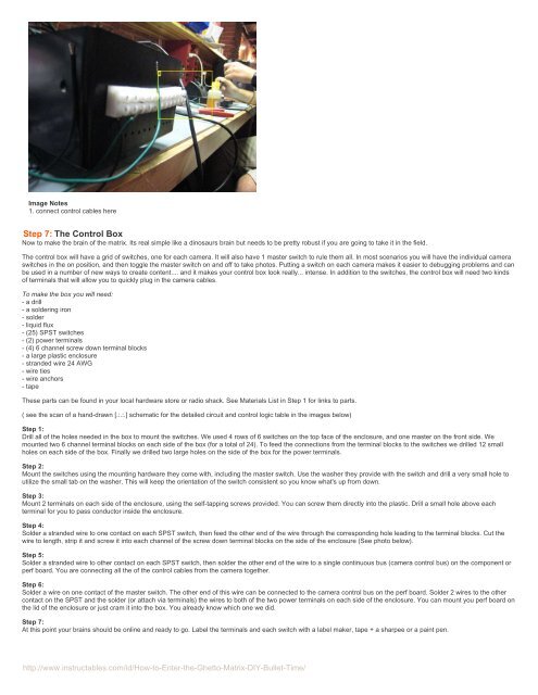
Image Notes<br />
1. connect control cables here<br />
Step 7: The Control Box<br />
Now <strong>to</strong> make <strong>the</strong> brain of <strong>the</strong> matrix. Its real simple like a dinosaurs brain but needs <strong>to</strong> be pretty robust if you are going <strong>to</strong> take it in <strong>the</strong> field.<br />
The control box will have a grid of switches, one for each camera. It will also have 1 master switch <strong>to</strong> rule <strong>the</strong>m all. In most scenarios you will have <strong>the</strong> individual camera<br />
switches in <strong>the</strong> on position, and <strong>the</strong>n <strong>to</strong>ggle <strong>the</strong> master switch on and off <strong>to</strong> take pho<strong>to</strong>s. Putting a switch on each camera makes it easier <strong>to</strong> debugging problems and can<br />
be used in a number of new ways <strong>to</strong> create content.... and it makes your control box look really... intense. In addition <strong>to</strong> <strong>the</strong> switches, <strong>the</strong> control box will need two kinds<br />
of terminals that will allow you <strong>to</strong> quickly plug in <strong>the</strong> camera cables.<br />
To make <strong>the</strong> box you will need:<br />
- a drill<br />
- a soldering iron<br />
- solder<br />
- liquid flux<br />
- (25) SPST switches<br />
- (2) power terminals<br />
- (4) 6 channel screw down terminal blocks<br />
- a large plastic enclosure<br />
- stranded wire 24 AWG<br />
- wire ties<br />
- wire anchors<br />
- tape<br />
These parts can be found in your local hardware s<strong>to</strong>re or radio shack. See Materials List in Step 1 for links <strong>to</strong> parts.<br />
( see <strong>the</strong> scan of a hand-drawn [.:.:.] schematic for <strong>the</strong> detailed circuit and control logic table in <strong>the</strong> images below)<br />
Step 1:<br />
Drill all of <strong>the</strong> holes needed in <strong>the</strong> box <strong>to</strong> mount <strong>the</strong> switches. We used 4 rows of 6 switches on <strong>the</strong> <strong>to</strong>p face of <strong>the</strong> enclosure, and one master on <strong>the</strong> front side. We<br />
mounted two 6 channel terminal blocks on each side of <strong>the</strong> box (for a <strong>to</strong>tal of 24). To feed <strong>the</strong> connections from <strong>the</strong> terminal blocks <strong>to</strong> <strong>the</strong> switches we drilled 12 small<br />
holes on each side of <strong>the</strong> box. Finally we drilled two large holes on <strong>the</strong> side of <strong>the</strong> box for <strong>the</strong> power terminals.<br />
Step 2:<br />
Mount <strong>the</strong> switches using <strong>the</strong> mounting hardware <strong>the</strong>y <strong>com</strong>e with, including <strong>the</strong> master switch. Use <strong>the</strong> washer <strong>the</strong>y provide with <strong>the</strong> switch and drill a very small hole <strong>to</strong><br />
utilize <strong>the</strong> small tab on <strong>the</strong> washer. This will keep <strong>the</strong> orientation of <strong>the</strong> switch consistent so you know what's up from down.<br />
Step 3:<br />
Mount 2 terminals on each side of <strong>the</strong> enclosure, using <strong>the</strong> self-tapping screws provided. You can screw <strong>the</strong>m directly in<strong>to</strong> <strong>the</strong> plastic. Drill a small hole above each<br />
terminal for you <strong>to</strong> pass conduc<strong>to</strong>r inside <strong>the</strong> enclosure.<br />
Step 4:<br />
Solder a stranded wire <strong>to</strong> one contact on each SPST switch, <strong>the</strong>n feed <strong>the</strong> o<strong>the</strong>r end of <strong>the</strong> wire through <strong>the</strong> corresponding hole leading <strong>to</strong> <strong>the</strong> terminal blocks. Cut <strong>the</strong><br />
wire <strong>to</strong> length, strip it and screw it in<strong>to</strong> each channel of <strong>the</strong> screw down terminal blocks on <strong>the</strong> side of <strong>the</strong> enclosure (See pho<strong>to</strong> below).<br />
Step 5:<br />
Solder a stranded wire <strong>to</strong> o<strong>the</strong>r contact on each SPST switch, <strong>the</strong>n solder <strong>the</strong> o<strong>the</strong>r end of <strong>the</strong> wire <strong>to</strong> a single continuous bus (camera control bus) on <strong>the</strong> <strong>com</strong>ponent or<br />
perf board. You are connecting all <strong>the</strong> of <strong>the</strong> control cables from <strong>the</strong> camera <strong>to</strong>ge<strong>the</strong>r.<br />
Step 6:<br />
Solder a wire on one contact of <strong>the</strong> master switch. The o<strong>the</strong>r end of this wire can be connected <strong>to</strong> <strong>the</strong> camera control bus on <strong>the</strong> perf board. Solder 2 wires <strong>to</strong> <strong>the</strong> o<strong>the</strong>r<br />
contact on <strong>the</strong> SPST and <strong>the</strong> solder (or attach via terminals) <strong>the</strong> wires <strong>to</strong> both of <strong>the</strong> two power terminals on each side of <strong>the</strong> enclosure. You can mount you perf board on<br />
<strong>the</strong> lid of <strong>the</strong> enclosure or just cram it in<strong>to</strong> <strong>the</strong> box. You already know which one we did.<br />
Step 7:<br />
At this point your brains should be online and ready <strong>to</strong> go. Label <strong>the</strong> terminals and each switch with a label maker, tape + a sharpee or a paint pen.<br />
http://www.instructables.<strong>com</strong>/id/<strong>How</strong>-<strong>to</strong>-<strong>Enter</strong>-<strong>the</strong>-Ghet<strong>to</strong>-<strong>Matrix</strong>-<strong>DIY</strong>-<strong>Bullet</strong>-<strong>Time</strong>/