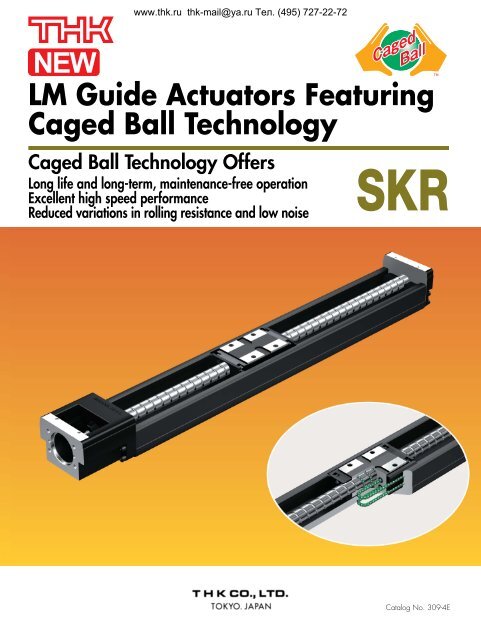
LM Guide Actuators Featuring Caged Ball Technology
LM Guide Actuators Featuring Caged Ball Technology
LM Guide Actuators Featuring Caged Ball Technology
- No tags were found...

Create successful ePaper yourself
Turn your PDF publications into a flip-book with our unique Google optimized e-Paper software.
www.thk.ru thk-mail@ya.ru Тел. (495) 727-22-726. High SpeedThrough the use of <strong>Caged</strong> <strong>Ball</strong> <strong>Technology</strong>, the SKR-type is compatible with the latest high-speedrotational AC servo-motors (6000 min -1 ), achieving higher speeds than the conventional KR-type.The ball screw lead settings of the conventional KR33 type were 6 mm and 10 mm. To achieve ahigher feed rate, a 20 mm ball screw lead has been added to the new SKR 33 series.Table 3 Maximum Traverse RateModel No.<strong>Ball</strong> Screwlead (mm)<strong>LM</strong> rail length(mm)Maximum travel speed (mm/s)Long block Short block150600200600300600064006005006006005525307003933641501,0002001,0003001,000SKR33104001,0005001,0006009208397006566071502,000—2002,000—3002,000—204002,000—5002,000—6001,780—7001,276—3401,000—4401,000105406401,0001,000914740736667SKR469403404312,0004004402,000205406401,9882,0001,7747401,4331,300940845784The maximum travel speed of the SKR-type is limited by the critical speed of the ball screw shaft, regardless ofthe maximum rotational speed (6000 min -1 ) of the motor. Please keep this in mind when using the SKR-type inhigh-speed applications.Please contact THK if you are considering using an SKR model at a rate higher than the maximum travel speednoted above.3
Modelswww.thk.ru thk-mail@ya.ru Тел. (495) 727-22-72SKR-AThis is the typical SKR model.SKR-BThis is the model in which two nut blocks of the SKR-Amodel are provided to achieve higher rigidity, higher loadcapacity, and higher precision.SKR-CThis is the model in which the full length of the SKR-Amodel nut block is shortened to have a longer stroke.Note that the SKR3320 model has no short type block.SKR-DThis is the model in which two SKR-C model nut blocksare provided. By placing two blocks, it achieves high rigiditywithin the application limits.Note that the SKR3320 model has no short type block.5
www.thk.ru thk-mail@ya.ru Тел. (495) 727-22-72Load Rating and Static Permissible Moment in Each Direction● Load RatingThe SKR-type <strong>LM</strong> guide actuators with <strong>Caged</strong> <strong>Ball</strong><strong>Technology</strong> consist of the <strong>LM</strong> guide, ball screw,and support bearing. Table 4 shows the load rating.P TP LP RP T• <strong>LM</strong> guide section unitThe SKR-type can carry loads in all directions, i.e., the radial, reverse-radial, and two lateral directions. Thebasic load rating is the same in these four directions and their values are shown in Table 4.• <strong>Ball</strong> screw section unitThe SKR-type can carry loads in the axial direction since it incorporates a ball screw nut in the nut block. Thebasic load rating value is shown in Table 4.• Support bearing unitThe SKR-type can carry loads in the axial direction since it incorporates an angular bearing in housing A. Thebasic load rating value is shown in Table 4.● Equivalent Load (<strong>LM</strong> <strong>Guide</strong> Unit)When loads are simultaneously applied to the SKR-type's <strong>LM</strong> guide in all directions, the equivalent load isobtained by the following equation.P E= P R(P L) + P TP E: equivalent load (N)In the radial directionIn the reverse-radial directionIn the lateral directionsP R: radial load (N)P L: reverse-radial load (N)P T: load in the lateral directions (N)Table 4 Load ratingBasic dynamicload rating C (N)ModelLong nut block types A, BShort nut block types C, DSKR331700011300<strong>LM</strong> <strong>Guide</strong>Basic staticLong nut block types A, B20400load rating C0 (N) Short nut block types C, D11500Radial clearance (mm)Normal grade, high accuracy grade 0 to –0.004Precision quality grade–0.004 to –0.012Screw shaft outer diameter (mm)13Lead (mm)6 10 20<strong>Ball</strong> ScrewThread minor diameter (mm)10.8<strong>Ball</strong> center-to-center diameter (mm)13.5Basic dynamic load rating Ca (N)4400 2700 2620Basic static load rating C0a (N)6290 3780 3770SupportBearingBasic dynamic load rating Ca (N)Static permissible load P0a (N)62502700Notes: • The load rating of the <strong>LM</strong> guide is the load rating per nut block.• Model SKR3320 has no short type block.SKR46395002840045900287000 to –0.006–0.006 to –0.0161510 2012.515.754350 42406990 7040670033306
www.thk.ru thk-mail@ya.ru Тел. (495) 727-22-72● Permissible Moment (<strong>LM</strong> <strong>Guide</strong> Unit)The SKR-type's <strong>LM</strong> guide section can carry moment loads in all directions, even though it uses only one nutblock. Table 5 shows static permissible moment values in the M A, M B, and M Cdirections.With a single long nut block (type A) With double long nut blocks (type B)With a single short nut block (type C) With double short nut blocks (type D)Figure 7 Static permissible moment in Each DirectionTable 5 Static permissible moment Unit: N·mModelStatic permissible momentNote 1: Symbol A, B, C, or D at the end of the modelnumber represents the type of nut block and theM AM BM Cnumber of them in use.SKR33 - A 173 173 424A: With a single long nut blockB: With double long nut blocksSKR33 - B 990 990 848C: With a single short nut blockSKR33 - C 5858 240D: With double short nuts blocksSKR33 - DSKR46 - ASKR46 - BSKR46 - CSKR46 - D3905793240236146039057932402361460480139027808701740Note 2: The values for models SKR-B/D indicate thevalues when double nut blocks are used inclose contact with each other.Service LifeThe SKR-type <strong>LM</strong> guide actuator with <strong>Caged</strong> <strong>Ball</strong> <strong>Technology</strong> consists of the <strong>LM</strong> guide, ball screw, and support bearing. TheService Life of each constituting component can be calculated based on the basic dynamic load rating shown in Rated Loads(Table 4 on p. 6).● Calculation of Service Life1) <strong>LM</strong> <strong>Guide</strong> Unit■ Nominal LifeThe nominal life (L) refers to the total traveling distance that 90% of a group of the same <strong>LM</strong> guides can achieve withoutflaking (flakes peeling off the metal surface) when these <strong>LM</strong> guides are individually moved under the same conditions.The nominal life of the <strong>LM</strong> guide can be obtained by equation (1).L =3f • CC× 50f • WP C(1)L : Nominal life (km)C : Basic dynamic load rating (N)Pc : Calculated applied load (N)fw : Load factor (see Table 7)fc : Contact factor (see Table 6)• If moment is acted on the SKR-type when using the SKR-A/-C type or the SKR-B/-D type of closely linked double nut blocks,multiply the acting moment by the equivalent coefficient shown in Table 8 to calculate equivalent load.P m= K MPm : Equivalent load (per nut block) (N)K : Equivalent moment factorM : Applied moment (Nmm)(If the SKR-type is used using three or more nut blocks or with the span separated, contact THK.)Particularly, if moment acts upon the SKR-B or SKR-D, use the following equation:P m =K C M C2• If a radial load (P) and moment load act on the SKR-type simultaneously, use the following equation to calculate the life span:P E= Pm + PPE : Overall equivalent radial load (N)7
www.thk.ru thk-mail@ya.ru Тел. (495) 727-22-72■ Service Life TimeWhen the nominal life (L) is obtained, the life span can be calculated by equation (2) if the stroke length andreciprocations of the system per minute are defined.L h =L 10 62 S 1 60Lh : Service life time (h)s : Stroke length (mm)n1 : Number of reciprocations per minute (min -1 )2) <strong>Ball</strong> Screw Unit and Bearing Unit (Fixed side)■ Nominal LifeThe nominal life (L) refers to the total number of revolutions that 90% of a group of the same <strong>Ball</strong> Screw(Bearings) can achieve without flaking when individually operated under the exact conditions.The nominal life of the <strong>Ball</strong> Screw Unit or bearing unit (fixed side) is calculated by equation (3).L =3C a× 10 6f • WF a(3)L : Nominal life (rev.)Ca : Basic dynamic load rating (N)Fa : Axial load (N)fw : Load factor (see Table 7)■ Service Life TimeWhen the nominal life (L) is obtained, the life span can be calculated by equation (4) if the stroke length andreciprocations of the system per minute are defined.L h =L 2 S n 1 60(4)Lh: Service life time(h)s: Stroke length (mm)n1: Number of reciprocations per minute (min -1 ): <strong>Ball</strong> Screw lead (mm)● f C : Contact FactorIf two nut blocks are used and closely linked together in theSKR-B or SKR-D type, multiply the basic load rating by thecontact factor shown in Table 6.● f w : Load FactorTable 7 shows the load factor.Table 6 Contact Factor (fC)Block typeA/C TypeB/D TypeContact Factor fC1.00.81Table 7 Load Factor (f W)Vibration or Impact Speed (V) fWFaintWeakMediumStrongVery low:V 0.25 m/sSlow:0.25 < V 1.0 m/sMedium:1.0 < V 2.0 m/sHigh:V > 2.0 m/s1.0 to 1.21.2 to 1.51.5 to 2.02.0 to 3.5● K: Moment Equivalent Factor (<strong>LM</strong> guide Unit)If a moment load is incurred, the load-carrying distribution on the <strong>LM</strong> guide increases locally. In this case, multiply themoment value with the moment equivalent factor shown in Table 8 to make the load calculation.K A, K B, and K Cshow the moment equivalent loads in the M A, M B, and M Cdirections respectively.Table 8 Moment Equivalent Factor (K)Model No.K AK BK C(2)SKR33 - ASKR33 - BSKR33 - CSKR33 - DSKR46 - ASKR46 - BSKR46 - CSKR46 - D1.42×10 -12.47×10 -22.39×10 -13.54×10 -29.51×10 -21.70×10 -21.46×10 -12.36×10 -2 1.42×10 -12.47×10 -22.39×10 -13.54×10 -29.51×10 -21.70×10 -21.46×10 -12.36×10 -2 5.05×10 -25.05×10 -25.05×10 -25.05×10 -23.46×10 -23.46×10 -23.46×10 -23.46×10 -2KA: moment equivalent factor in the MA directionKB: moment equivalent factor in the MB directionKC: moment equivalent factor in the MC directionNote: For the SKR-B and SKR-D types, the moment equivalent factor shows the value applied when two nut blocks areclosely linked together.8
www.thk.ru thk-mail@ya.ru Тел. (495) 727-22-72Accuracy StandardsThe tables below show the accuracy standards of the SKR-type.Table 9-1 Normal Grade (No Symbol)Table 9 Accuracy StandardsUnit: mmModel No.Rail LengthPositioningRepeatabilityPositioningAccuracyRunning ofParallelismBacklashStarting Torque(N-cm)150200SKR33SKR46300400500600700340440540640740940± 0.010± 0.010No standarddefinedNo standarddefinedNo standarddefinedNo standarddefined0.0200.020710Table 9-2 High-accuracy Grade (H)Unit: mmModel No.Rail LengthPositioningRepeatabilityPositioningAccuracyRunning ofParallelismBacklashStarting Torque(N-cm)150SKR33SKR46200300400500600700340440540640740940± 0.005± 0.0050.0600.1000.1200.1000.1200.1500.0250.0350.0400.0350.0400.0500.02070.020 10Table 9-3 Precision Grade (P)Unit: mmModel No.Rail LengthPositioningRepeatabilityPositioningAccuracyRunning ofParallelismBacklashStarting Torque(N-cm)9SKR33SKR46150200300400500600700340440540640740± 0.003± 0.0030.0200.0250.0300.0250.030The evaluation method complies with THK standards.The starting torque shows a value achieved when THK AFB-LF grease is used with the product.If high-viscosity grease, such as vacuum grease or clean room grease, is used, there are cases where thecriteria value is exceeded. In such a case, exercise care when selecting the motor.0.0100.0150.0200.0150.0200.0030.003151517
www.thk.ru thk-mail@ya.ru Тел. (495) 727-22-72Accuracy StandardsThe precision of the SKR is determined by repetitive positioning repeatability, positioning accuracy, backlash, and runningparallelism.● Positioning RepeatabilityRepeat the measurement seven times from the samedirection to a certain point. Divide the maximum differenceby two. Conduct the same test at three points, the “center”of the stroke, and on both the approximate maximum andminimum positions of travel. Add ± to the largest difference.This accuracy is generally measured with a laserinterferometer and sometimes with a dial-gauge.(Taken from THK Accuracy & Measurement Standards.)t1t2t3Figure. 8 Positioning Repeatability● Positioning AccuracyThe maximum stroke is taken as the reference length, andthe maximum error between the actual distance traveledfrom the reference position and the instructed value isexpressed as an absolute value.(+)A(Error)Referenceposition0A Instructed valueA Distance traveledA=| Distance actually traveled –Instructed travel distance value(-)Figure. 9 Positioning Accuracy● BacklashLock the actuator’s carriage into a fixed position via theactuator’s drive mechanism. Do not lock the actuator’scarriage by “fixing” it rigidly. Push the carriage from onedirection with a predetermined external force using a push/pull gauge. Zero out the dial-gauge while the axial force isbeing applied-release the external force and read the dialgauge.Measure at three separate points along the stroke,at the center and the end of travel positions. Backlash isthe maximum measured value.BacklashScrew feedLoadReturnLoad displacement(including elastic displacement)Figure. 10 Backlash● Running of ParallelismA straightedge is placed on a leveling plate mounted withthe SKR, and parallelism is measured over almost the entiredistance traveled using a test indicator. The maximum errorin the reading within the distance traveled is taken as themeasurement value.StraightedgeFigure. 11 Running of Parallelism10
SKR33 Standard Typewww.thk.ru thk-mail@ya.ru Тел. (495) 727-22-72SKR33 A (with a Single Long Block)SKR33 B (with Two Long Blocks)59L1<strong>LM</strong> rail length11765411 304-M5 depth 6 2 × n1-M2.6 depth 4823H8.52-M2 depth 5 2 × n-5.5 through holeFø9.5 counter bore depth 5.4(n1-1) × F(H)10271692276 MIN(Dimension withtwo nut blocksin close contact)Aø30H8288h7øø2B3G100(n-1)×100B(G)2-M3 depth 5 59.6 2-M4 through3437.43020.330 °43.30.7 42.6PCD4030 °2-M4 depth 8202.630 15602933A arrow viewB - B cross section<strong>LM</strong> RailLength(mm)150200300400500600700OverallLengthL1 (mm)220270370470570670770Available Stroke Range (mm) H G FOverall main unit mass (kg)n n1Type A Type B (mm) (mm) (mm)Type A Type B5525 25 100 2 2 1.710550 50 100 2 2 2.1205 129 50 50 200 3 2 2.83.1305 229 100 50 200 4 2 3.53.8405 329 50 50 200 5 3 4.24.5505 429 100 50 200 6 3 5.05.3605 529 50 50 200 7 4 5.76.0The available stroke range of SKR33B shows a value applicable when the product is used with two long type blocks closelylinked together.How to Interpret the Model Number11SKR33 20 A + 700L P 0 - 0 0 0 01 2 3 4 5 6 7 8 9 101 Model number 2 <strong>Ball</strong> screw lead (mm) 3 Type of nut block 4 <strong>LM</strong> rail length (mm)5 Accuracy grade 6 With/without a motor 7 With/without a cover8 Sensor specifications (see page 19) 9 Type of housing – A: 010 Type of intermediate flange (see page 20) 11 Control number11
www.thk.ru thk-mail@ya.ru Тел. (495) 727-22-72SKR33 C (with a Single Short Block)SKR33 D (with Two Short Blocks)59L 1<strong>LM</strong> rail length111150.52-M2 depth 5 28.52 × n1-M2.6 depth 48238.52-M5 depth 6HF(n1-1) × F2 × n-5.5 through holeø9.5 counter bore depth 5.4(H)1027 2216950.5(Dimension withtwo nut blocksin close contact)Aø30H8ø 28ø 8h72B3G100(n-1) × 100B(G)2-M3 depth 5 59.62-M4 through3437.43020.330 °43.30.7 42.6PCD4030 °2-M4 depth 8202.63060152933A arrow viewB - B cross section<strong>LM</strong> RailLength(mm)150200300400500600700OverallLengthL1 (mm)220270370470570670770Available Stroke Range (mm) H G FOverall main unit mass (kg)n n1Type C Type D (mm) (mm) (mm)Type C Type D80.5130.5230.5330.5430.5530.5630.53080180280380480580255050100501005025505050505050100100200200200200200223456722223341.62.02.73.44.14.85.51.82.12.83.64.35.05.7The available stroke range of SKR33D shows a value applicable when the product is used with two short type blocks closelylinked together.567AccuracygradeProvisionof MotorProvisionof CoverDescriptionSymbolDescriptionSymbolDescriptionSymbolNormal gradeNo SymbolNot provided0Not provided0High-accuracy gradePrecision gradeHPProvided (assembled at THK)1Provided112
SKR33 (with the Cover)www.thk.ru thk-mail@ya.ru Тел. (495) 727-22-72SKR33 A (with a Single Long Block)SKR33 B (with Two Long Blocks)4-M5 depth 1076543054-M2 depth 4(from the back side)BAB2-M3 depth 559.6342-M4 through(0.85)86746445.542.329312030 °30 °48410.7PCD402-M4 depth 83060152.6A arrow viewB - B cross section<strong>LM</strong> RailLength(mm)OverallLengthL1 (mm)Available Stroke Range (mm) H G FOverall main unit mass (kg)n n1Type A Type B (mm) (mm) (mm)Type A Type B15020030040050060070022027037047057067077055105205305405505605129229329429529255050100501005025505050505050100100200200200200200223456722223341.92.33.13.84.65.36.13.54.25.05.76.5The available stroke range of SKR33B shows a value applicable when the product is used with two long type blocks closelylinked together.How to Interpret the Model Number11SKR33 20 A + 700L P 0 - 0 0 0 01 2 3 4 5 6 7 8 9 101 Model number 2 <strong>Ball</strong> screw lead (mm) 3 Type of nut block 4 <strong>LM</strong> rail length (mm)5 Accuracy grade 6 With/without a motor 7 With/without a cover8 Sensor specifications (see page 19) 9 Type of housing – A: 010 Type of intermediate flange (see page 20) 11 Control number13
www.thk.ru thk-mail@ya.ru Тел. (495) 727-22-72SKR33 C (with a Single Short Block)50.528.5SKR33 D (with Two Short Blocks)4-M2 depth 4(from the back side)5 212-M5 depth 10BB862-M3 depth 559.6342-M4 through(0.85)746430 °45.542.32030 °0.729314148PCD402-M4 depth 83060152.6A arrow viewB - B cross section<strong>LM</strong> RailLength(mm)OverallLengthL1 (mm)Available Stroke Range (mm) H G FOverall main unit mass (kg)n n1Type C Type D (mm) (mm) (mm)Type C Type D15020030040050060070022027037047057067077080.5130.5230.5330.5430.5530.5630.53080180280380480580255050100501005025505050505050100100200200200200200223456722223341.82.22.93.74.45.25.92.02.33.13.84.65.36.1The available stroke range of SKR33D shows a value applicable when the product is used with two short type blocks closelylinked together.567AccuracygradeProvisionof MotorProvisionof CoverDescriptionSymbolDescriptionSymbolDescriptionSymbolNormal gradeNo SymbolNot provided0Not provided0High-accuracy gradePrecision gradeHPProvided (assembled at THK)1Provided114
SKR46 Standard Typewww.thk.ru thk-mail@ya.ru Тел. (495) 727-22-72SKR46 A (with a Single Long Block)SKR46 B (with Two Long Blocks)87.5L1<strong>LM</strong> rail length131102-M6 depth 98112.5 462 × n1-M2.6 depth 4946H102002-M2 depth 5 2 × n-6.6 through holeø11 counter bore depth 6.5(n1-1) ×200(H)14 48.5 252818110(Dimension withtwo nut blocksin close contact)2BAø46H8ø42ø10h7G100(n-1)×100B (G)85.44-M4 depth 854.44658.357.126.330 °30 °1.2295.740.846PCD6046 2086A arrow viewB - B cross section<strong>LM</strong> RailLength(mm)340440540640740940OverallLengthL1 (mm)440.5540.5640.5740.5840.51040.5Available Stroke Range (mm) H GOverall main unit mass (kg)n n1Type A Type B (mm) (mm)Type A Type B208.5308.5408.5508.5608.5808.598.5198.5298.5398.5498.5698.57020702070707070707070703456792334456.47.89.210.612.014.87.48.710.111.512.915.7The available stroke range of SKR46B shows a value applicable when the product is used with two long type blocks closelylinked together.How to Interpret the Model Number11SKR46 20 A + 940L P 0 - 0 0 0 01 2 3 4 5 6 7 8 9 101 Model number 2 <strong>Ball</strong> screw lead (mm) 3 Type of nut block 4 <strong>LM</strong> rail length (mm)5 Accuracy grade 6 With/without a motor 7 With/without a cover8 Sensor specifications (see page 19) 9 Type of housing – A: 010 Type of intermediate flange (see page 20) 11 Control number15
www.thk.ru thk-mail@ya.ru Тел. (495) 727-22-72SKR46 C (with a Single Short Block)SKR46 D (with Two Short Blocks)KR15 (With the Cover)87.5L 1<strong>LM</strong> rail length1312.52-M6 depth 977482 × n1-M2.6 depth 4946102-M2 depth 5 2 × n-6.6 through holeø11 counter bore depth 6.5200H (n1-1) × 200(H)1448.5 25281877(Dimension withtwo nut blocksin close contact)2BAø46H8ø42ø10h73.5 G100(n-1) × 100B (G)85.44-M4 depth 854.44658.357.15.740.84626.330 °30 °291.2PCD60468620A arrow viewB - B cross section<strong>LM</strong> RailLength(mm)340440540640740940OverallLengthL1 (mm)440.5540.5640.5740.5840.51040.5Available Stroke Range (mm) H GOverall main unit mass (kg)n n1Type A Type B (mm) (mm)Type A Type B241.5341.5441.5541.5641.5841.5164.5264.5364.5464.5564.5764.57020702070707070707070703456792334456.17.58.910.311.714.56.78.19.510.812.215.0The available stroke range of SKR46D shows a value applicable when the product is used with two short type blocks closelylinked together.567AccuracygradeProvisionof MotorProvisionof CoverDescriptionSymbolDescriptionSymbolDescriptionSymbolNormal gradeNo SymbolNot provided0Not provided0High-accuracy gradePrecision gradeHPProvided (assembled at THK)1Provided116
SKR46 (with the Cover)www.thk.ru thk-mail@ya.ru Тел. (495) 727-22-72SKR46 A (with a Single Long Block)SKR46 B (with Two Long Blocks)110814-M6 depth 12 46304-M5 depth 104-M2.6 depth 5(from the back side)5BAB85.44-M4 depth 8(1.8)112100882630 °641.2 56.8PCD6030 °4686205.740.8435668A arrow viewB - B cross section<strong>LM</strong> RailLength(mm)OverallLengthL1 (mm)Available Stroke Range (mm) H GOverall main unit mass (kg)n n1Type A Type B (mm) (mm)Type A Type B340440540640740940440.5540.5640.5740.5840.51040.5208.5308.5408.5508.5608.5808.598.5198.5298.5398.5498.5698.57020702070707070707070703456792334457.18.610.011.513.016.08.39.811.312.714.217.2The available stroke range of SKR46B shows a value applicable when the product is used with two long type blocks closelylinked together.How to Interpret the Model Number11SKR46 20 A + 940L P 0 - 0 0 0 01 2 3 4 5 6 7 8 9 101 Model number 2 <strong>Ball</strong> screw lead (mm) 3 Type of nut block 4 <strong>LM</strong> rail length (mm)5 Accuracy grade 6 With/without a motor 7 With/without a cover8 Sensor specifications (see page 19) 9 Type of housing – A: 010 Type of intermediate flange (see page 20) 11 Control number17
www.thk.ru thk-mail@ya.ru Тел. (495) 727-22-72SKR46 C (with a Single Short Block)SKR46 D (with Two Short Blocks)KR15 (With the Cover)774-M6 depth 12484-M2.6 depth 5(from the back side)535.5BAB11285.44-M4 depth 8(1.8)1008830 °6456.82630 °40.81.2435668PCD6046 20865.7A arrow viewB - B cross section<strong>LM</strong> RailLength(mm)OverallLengthL1 (mm)Available Stroke Range (mm) H GOverall main unit mass (kg)n n1Type C Type D (mm) (mm)Type C Type D340440540640740940440.5540.5640.5740.5840.51040.5241.5341.5441.5541.5641.5841.5164.5264.5364.5464.5564.5764.57020702070707070707070703456792334456.68.19.611.012.515.57.48.910.311.813.316.3The available stroke range of SKR46D shows a value applicable when the product is used with two short type blocks closelylinked together.567AccuracygradeProvisionof MotorProvisionof CoverDescriptionSymbolDescriptionSymbolDescriptionSymbolNormal gradeNo SymbolNot provided0Not provided0High-accuracy gradePrecision gradeHPProvided (assembled at THK)1Provided118
Sealswww.thk.ru thk-mail@ya.ru Тел. (495) 727-22-72The SKR is equipped with an end seal and side seal as standard for dust-proofing.Side sealEnd sealSensorsProximity sensors and photosensors are available as options for the SKR33 and SKR46. When a customer specifiesa model with a sensor, specially designed sensor rails and sensor dogs are supplied with the product.● Sensor SpecificationsSymbol012456789ABCDEFDescriptionNoneWith sensor rail3 photosensors3 proximity sensorsNormally OPEN3 proximity sensorsNormally OPEN3 photosensors3 proximity sensorsNormally OPEN3 proximity sensorsNormally OPEN3 proximity sensorsNormally CLOSED3 proximity sensorsNormally CLOSED3 proximity sensorsNormally CLOSEDProximity sensorNormally OPEN (1),Normally CLOSED (2)Proximity sensorNormally OPEN (1),Normally CLOSED (2)Proximity sensorNormally OPEN (1),Normally CLOSED (2)Proximity sensorNormally OPEN (1),Normally CLOSED (2)(PNP OUTPUT)Type––EE-SX671 (OMRON)GL-12F (SUNX)GXL-N12F (SUNX)EE-SX674 (OMRON)APM-D3A1-001(YAMATAKE)GL-N12F (SUNX)GL-N12FB (SUNX)GXL-N12FB (SUNX)APM-D3B1-003(YAMATAKE)GL-N12F (1 unit),GL-N12FB (2 units)GXL-N12F (1 unit),GXL-N12FB (2 units)APM-D3A1-001 (1 unit),APM-D3B1-003 (2 units)GXL-N12F-P (1 unit),GXL-N12FB-P (2 units)Accessory–Mounting screwMounting screw/nut, detecting plate, sensor rail,mounting plate, connector (EE-1001)Mounting screw/nut, detecting plate, sensor rail,fixture (MS-GL12)Mounting screw/nut, detecting plate, sensor rail,fixture (MS-GXL12)Mounting screw/nut, detecting plate, sensor rail,mounting plate, connector (EE-1001)Mounting screw/nut, detecting plate, sensor railMounting screw/nut, detecting plate, sensor railMounting screw/nut, detecting plate, sensor railMounting screw/nut, detecting plate, sensor rail,fixture (MS-GXL12)Mounting screw/nut, detecting plate, sensor railMounting screw/nut, detecting plate, sensor railMounting screw/nut, detecting plate, sensor rail,fixture (MS-GXL12)Mounting screw/nut, detecting plate, sensor railMounting screw/nut, detecting plate, sensor rail,fixture (MS-GXL12)19
www.thk.ru thk-mail@ya.ru Тел. (495) 727-22-72● SensorsProximity sensors GL-12 (SUNX)3 units● Sensor railsIt is also possible to install a sensor railGL-N12F (B) (SUNX) 3 unitsonly.GXL-N12F (B) (SUNX) 3 unitsAPM-D3A1-001 (Yamatake) 3 units(APM-D3B1-003)Photosensors EE-SX671 (OMRON) 3 unitsEE-SX674 (OMRON) 3 unitsConnectors EE-1001 (OMRON) 3 unitsNote: Connectors come as standard with photosensors.Proximity sensors GL-12F, GL-N12F (B), and GXL-N12F (B) (SUNX)abModelSKR33SKR46Unit: mma b c d44.757.721.813.824.81422cdProximity sensors APM-D3A1 and APM-D3B1 (Yamatake)abModelSKR33SKR46Unit: mma b c d43.0556.20.30.214.826.81522cdPhotosensor EE-SX671 (OMRON)fgehjiModelSKR33SKR46Unit: mme f g h i j51.164.163.676.68.38.318.829.87.416.419.526.5Photosensor EE-SX674 (OMRON)hifejgModelSKR33SKR46Unit: mme f g h i j45.9 52.1 3.3 17.8 7.1 2058.9 65.1 3.2 28.8 16.1 2720
www.thk.ru thk-mail@ya.ru Тел. (495) 727-22-72Intermediate Flanges● Applicable Motors and Applicable Intermediate FlangesThe SKR-type is provided with intermediate flanges so that a variety of motors can be installed. The table belowshows the control number of the intermediate flanges meeting the applicable motors on a model number basis.At the time of order, specify the intermediate flange control number.Table11 Table of Motors Used and Corresponding Motor BracketsMotor model No. Flange angle SKR33 SKR46SGMAH-A3 (30W) 0H 0FSGMAH-A5 (50W) 400H 0FSGMAH-01 (100W) 0H 0FSGMPH-01 (100W) – 04SGMAH-02 (200W) 60– 04SGMAH-04 (400W) – 04HC-MFS 053 (50W)0H0FHC-KFS 053 (50W)0H0F40HC-MFS 13 (100W)0H0FHC-KFS 13 (100W)0H0FHC-MFS 23 (200W) – 04HC-KFS 23 (200W) – 0460HC-MFS 43 (400W) – 04HC-KFS 43 (400W) – 04MSMA 3A (30W)0K0GMSMA 5A (50W)380K0GMSMA 01 (100W) 0K 0GMQMA 01 (100W) – 03MSMA 02 (200W) 60– 03MSMA 04 (400W) – 03Q1AA04003D (30W)0H0FQ1AA04005D (50W)400H0FQ1AA04010D (100W) 0H 0FQ1AA06020D (200W) – 0460Q1AA06040D (400W) – 04R88M-W03030 (30W)0H0FR88M-W05030 (50W)400H0FR88M-W10030 (100W) 0H 0FR88M-W20030 (200W) – 0460R88M-W40030 (400W) – 04β0.2/5000is (50W) 0H 0F40β0.3/5000is (100W) 0H 0Fβ0.4/5000is (125W) – 04β0.5/5000is (200W) 60– 04β1/5000is (400W) – 04AS 46, ASC46 420I –AS 6, ASC66 600G 01RK54 420I –RK56 600G 01UMK24 420I –UMK26 56.40F –CSK24 420I –CSK2656.4 0F –Note1) The symbols in the table each indicate the last two digits of an administration number.Note2) For the coupling for mounting a motor in the table, contact THK.ServomotorStepping motorYaskawa ElectricMitsubishi ElectricMatsushita ElectricSANYO ElectricOMRONFanucOriental MotorMELSERVO5 phase2 phase∑-2MINAS ASANMOTION Q1OMNUC Wβis seriesαStepJ2 SuperRKUMKCSK21
www.thk.ru thk-mail@ya.ru Тел. (495) 727-22-72Dimensions of the Intermediate Flanges4 - GFAEHousing A<strong>LM</strong> rail45 ° 45 ° A’ øC øDHPCD BSKR33SKR46Control number0B0H0K0203040A0F0GA × A’54 × 5442 × 4042 × 3862 × 6062 × 6062 × 6076 × 7662 × 5362 × 53B604645607070904645C503030505050703030D28282842424242E333.53.53.543.5F101010101010121010GM4M4M3M4M4M5M5M4M3H464 - GFABEHousing A<strong>LM</strong> railA’ øCøDHSKR33SKR46Control number0F0G01A × A’56.4 × 56.460 × 6062 × 60B47.145050C38.13636D2828E22F101010GM4M4M4H5.274 - X through holeøY counter bore depth Z (from the back side)FAEHousing A<strong>LM</strong> railA’ BøCøDHControl number A × A’ B C D E F X Y ZSKR33 0I 42 × 42 31 22 7 3.5 6 422
www.thk.ru thk-mail@ya.ru Тел. (495) 727-22-72<strong>LM</strong>-<strong>Guide</strong> Actuator SKR-typePrecautions on Use● Handling• Exercise care when handling the product. Dropping or tapping it may result in breakage.• Do not disassemble the product unless it is unavoidable. Disassembling the product unnecessarily may resultin the entry of foreign matter or cause accuracy degradation.• Operating the product exceeding the permissible revolution speed may lead to part breakage or accidents.The operating revolution speed should be limited to the range specified by THK.● Operating temperature range•The service temperature range of this product is 0 to 40°C (no freezing or condensation). If you consider usingthis product outside the service temperature range, contact THK.● Lubrication• To deliver the full extent of SKR-type functions, lubrication is essential. Use of the product without lubricationmay result in increased abrasion at the rolling section or shorter life.• Do not mix and use lubricants with different properties.• The greasing intervals differ with the operating conditions. It is recommended that the greasing intervals bedetermined at the initial inspection.• If the product is used in locations constantly exposed to vibration or in special environments such as clean rooms,vacuums, low temperatures, or high temperatures, there are cases where ordinary greases cannot be used. In suchcases, contact THK.● Use and Lubrication in Special Environments• If locations are constantly exposed to vibration or in special environments such as clean rooms, vacuums, lowtemperatures, or high temperatures, consult THK.● Safety precautions• If the product is operating or in the ready state, never touch a moving part. In addition, do not enter the operatingarea of the actuator.• If two or more people are involved in the operation, confirm the procedures such as a sequence, signs and anomaliesin advance, and appoint another person for monitoring the operation.● “<strong>LM</strong> <strong>Guide</strong>”, “<strong>Caged</strong> <strong>Ball</strong>” and “ ” are the registered trademarks of THK CO., LTD.● There may be differences between products appearing in photographs and the actual product.● The appearance, specifications, and other information are subject to change without prior notice to improvereliability, function, etc. When deciding to adopt the product, contact us beforehand.● We have exercised great care in preparing this catalog, but it is still possible that there are misspellings, omissionsof letters, etc. THK assumes no responsibility or liability for damage resulting from such errors possibly containedherein.● We employ the basic policy of observing the Foreign Exchange and Foreign Trade Control Law of Japan withregard to the export of our products/technologies or sales for export. For export of our products as discretecomponents, consult THK beforehand.All rights reserved.NORTH AMERICATHK America,Inc.HEADQUARTERSPhone:+1-847-310-1111 Fax:+1-847-310-1271CHICAGO OFFICEPhone:+1-847-310-1111 Fax:+1-847-310-1182NEW YORK OFFICEPhone:+1-845-369-4035 Fax:+1-845-369-4909ATLANTA OFFICEPhone:+1-770-840-7990 Fax:+1-770-840-7897LOS ANGELES OFFICEPhone:+1-949-955-3145 Fax:+1-949-955-3149SAN FRANCISCO OFFICEPhone:+1-925-455-8948 Fax:+1-925-455-8965BOSTON OFFICEPhone:+1-781-575-1151 Fax:+1-781-575-9295DETROIT OFFICEPhone:+1-248-858-9330 Fax:+1-248-858-9455TORONTO OFFICEPhone:+1-905-820-7800 Fax:+1-905-820-7811SOUTH AMERICATHK Brasil LTDAPhone:+55-11-3767-0100 Fax:+55-11-3767-0101EUROPETHK GmbHEUROPEAN HEADQUARTERSPhone:+49-2102-7425-0 Fax:+49-2102-7425-217HEAD OFFICE 3-11-6, NISHI-GOTANDA, SHINAGAWA-KU, TOKYO 141-8503 JAPANINTERNATIONAL SALES DEPARTMENT PHONE:+81-3-5434-0351 FAX:+81-3-5434-0353Global site : http://www.thk.com/DÜSSELDORF OFFICEPhone:+49-2102-7425-0 Fax:+49-2102-7425-299FRANKFURT OFFICEPhone:+49-2102-7425-650 Fax:+49-2102-7425-699STUTTGART OFFICEPhone:+49-7150-9199-0 Fax:+49-7150-9199-888MÜNCHEN OFFICEPhone:+49-8937-0616-0 Fax:+49-8937-0616-26U.K. OFFICEPhone:+44-1908-30-3050 Fax:+44-1908-30-3070ITALY MILANO OFFICEPhone:+39-039-284-2079 Fax:+39-039-284-2527ITALY BOLOGNA OFFICEPhone:+39-051-641-2211 Fax:+39-051-641-2230SWEDEN OFFICEPhone:+46-8-445-7630 Fax:+46-8-445-7639AUSTRIA OFFICEPhone:+43-7229-51400 Fax:+43-7229-51400-79SPAIN OFFICEPhone:+34-93-652-5740 Fax:+34-93-652-5746TURKEY OFFICEPhone:+90-216-362-4050 Fax:+90-216-569-7150THK France S.A.S.Phone:+33-4-3749-1400 Fax:+33-4-3749-1401CHINATHK (CHINA) CO.,LTD.HEADQUARTERSPhone:+86-411-8733-7111 Fax:+86-411-8733-7000SHANGHAI OFFICEPhone:+86-21-6219-3000 Fax:+86-21-6219-9890BEIJING OFFICEPhone:+86-10-8441-7277 Fax:+86-10-6590-3557CHENGDU OFFICEPhone:+86-28-8526-8025 Fax:+86-28-8525-6357GUANGZHOU OFFICEPhone:+86-20-8333-9770 Fax:+86-20-8333-9726THK (SHANGHAI) CO.,LTD.Phone:+86-21-6275-5280 Fax:+86-21-6219-9890TAIWANTHK TAIWAN CO.,LTD.TAIPEI HEAD OFFICEPhone:+886-2-2888-3818 Fax:+886-2-2888-3819TAICHUNG OFFICEPhone:+886-4-2359-1505 Fax:+886-4-2359-1506TAINAN OFFICEPhone:+886-6-289-7668 Fax:+886-6-289-7669KOREASEOUL REPRESENTATIVE OFFICEPhone:+82-2-3468-4351 Fax:+82-2-3468-4353SINGAPORETHK <strong>LM</strong> SYSTEM Pte. Ltd.Phone:+65-6884-5500 Fax:+65-6884-5550INDIABANGALORE REPRESENTATIVE OFFICEPhone:+91-80-2330-1524 Fax:+91-80-2314-8226©THK CO., LTD.20071003 E4 Printed in Japan