LM Guide Model HR
LM Guide Model HR
LM Guide Model HR
- No tags were found...

Create successful ePaper yourself
Turn your PDF publications into a flip-book with our unique Google optimized e-Paper software.
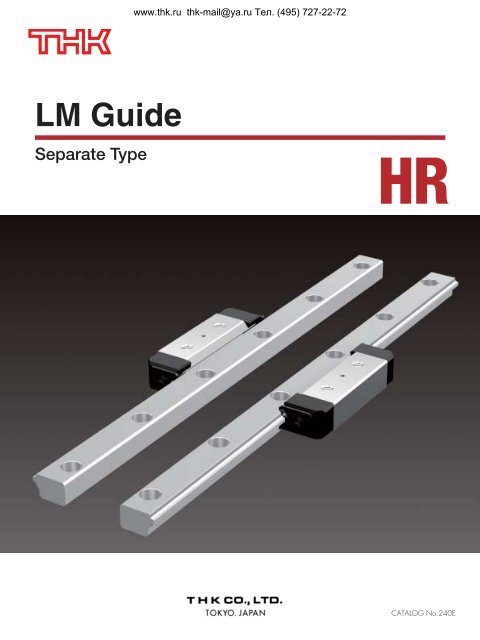
www.thk.ru thk-mail@ya.ru Тел. (495) 727-22-72<strong>LM</strong> <strong>Guide</strong>Separate Type<strong>HR</strong>CATALOG No.240E
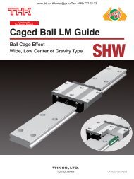
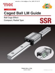
www.thk.ru thk-mail@ya.ru Тел. (495) 727-22-72<strong>HR</strong> Outline<strong>Model</strong> <strong>HR</strong> - Product OverviewWith a thin, highly rigid and space saving structure, model <strong>HR</strong> is interchangeable with the Cross Roller<strong>Guide</strong>.A stainless steel type is also available as standard.Major applications XYZ axes of electric discharge machine / precision table / XZ axes of NC lathe /assembly robot / conveyance system / machining center /wire-cutting electric discharge machine / tool changer / woodworking machine<strong>Model</strong> <strong>HR</strong>Heavy-load TypeThe <strong>LM</strong> blocks can be mounted from the top and the bottom.<strong>Model</strong> <strong>HR</strong>-TUltra-heavy Load TypeIt has the same sectional shape as model <strong>HR</strong>, but has agreater overall <strong>LM</strong> block length (L) and a higher load rating.
www.thk.ru thk-mail@ya.ru Тел. (495) 727-22-72*1: Dimensional table formodel <strong>HR</strong><strong>Model</strong> <strong>HR</strong> pages 11-12Rated Loads in All DirectionsWhen installed, one set of model <strong>HR</strong> iscapable of receiving loads in all fourdirections: radial, reverse-radial andlateral directions.The basic load ratings of an installed set ofmodel <strong>HR</strong> are equal in all four directions (radial,reverse-radial and lateral directions).The basic load ratings in the dimensionaltable* 1 for model <strong>HR</strong> indicate the values in theradial direction per <strong>LM</strong> block as shown in thefigure on the right.Reverse-radial directionLateraldirectionRadial directionLateraldirectionEquivalent LoadWhen the <strong>LM</strong> block of model <strong>HR</strong>receives loads in the reverse-radialand lateral directions simultaneously,the equivalent load is obtained fromthe equation below.wherePEPRPLPE :Equivalent load (N)⋅Radial direction⋅Reverse-radial direction⋅Lateral direction12PTPR :Radial load (N)PL :Reverse-radial load (N)PT :Lateral load (N)
www.thk.ru thk-mail@ya.ru Тел. (495) 727-22-72<strong>HR</strong> OUTLINE<strong>Model</strong> <strong>HR</strong> - Product OverviewService lifeThe service life of an <strong>LM</strong> <strong>Guide</strong> is subject to variations even under the sameoperational conditions. Therefore, it is necessary to use the rated life definedbelow as a reference value for obtaining the service life of the <strong>LM</strong> <strong>Guide</strong>.Rated lifeThe rated life means the total travel distancethat 90% of a group of units of the same <strong>LM</strong><strong>Guide</strong> model can achieve without flaking(scale-like exfoliation on the metal surface)after individually running under the sameconditions.Service life timeOnce the rated life (L) has been obtained, theservice life time can be obtained using theequation on the right if the stroke length andthe number of reciprocations are constant.fH · fT · fC CL = ( · ) 3 50fWPCL : Rated life (km)C : Basic dynamic load rating* 1 (N)PC : Calculated load (N)fH : Hardness factor (see Fig. 1)fT : Temperature factor (see Fig. 2)fC : Contact factor (see Table 1)fW : Load factor (see Table 2)L 10 6Lh =2 RS n1 60Lh : Service lifetime (h)Rs : Stroke length (mm)n1 : No. of reciprocations per min (min -1 )*1: Basic dynamic load rating(C)It refers to a load with aconstant magnitude anddirection under which therated life (L) of a group ofidentical <strong>LM</strong> <strong>Guide</strong> unitsindependently operating is50 km.fHHardness factorTo ensure the achievement of the optimum load capacity of the <strong>LM</strong> <strong>Guide</strong>,the raceway hardness must be between 58 and 64 <strong>HR</strong>C.At hardness below this range, the basic dynamic and static load ratingsdecrease. Therefore, the rating values must be multiplied by therespective hardness factors (fH).Since the <strong>LM</strong> <strong>Guide</strong> has sufficient hardness, the fH value for the <strong>LM</strong> <strong>Guide</strong>is normally 1.0 unless otherwise specified.Fig. 1 1.0Fig. 20.90.81.00.90.70.60.50.40.30.80.70.60.50.20.1Hardness factor fH60 50 40 30 20 10Raceway hardness (<strong>HR</strong>C)fTTemperature factorSince the service temperature of Caged Ball <strong>LM</strong> <strong>Guide</strong>s is normally 80Cor below, the fT value is 1.0.Temperature factor fT100 150 200Raceway temperature (°C)fCContact factorWhen multiple <strong>LM</strong> blocks are used in close contact with each other, it isdifficult to achieve uniform load distribution due to moment loads andmounting-surface accuracy. When using multiple blocks in close contactwith each other, multiply the basic load rating (C or C0) by thecorresponding contact factor indicated in Table 1.Note: When uneven load distribution is expected in a large machine, consider using a contactfactor from Table 1.Table 1 Contact Factor (fC)Number of blocks used in close contact Contact factor fC20.8130.7240.6650.616 or more0.6Normal use1fWLoad factorIn general, reciprocating machines tend to produce vibrations or impactduring operation. It is especially difficult to accurately determine allvibrations generated during high-speed operation and impacts producedeach time the machine starts and stops. Therefore, where the effects ofspeed and vibration are estimated to be significant, divide the basicdynamic load rating (C) by a load factor selected from Table 2, whichcontains empirically obtained data.Table 2 Load FactorfWVibration/impact Speed (V) fWFaintVery slowV0.25m/s1 to 1.2WeakSlow0.25V1m/s1.2 to 1.5ModerateMedium1V2m/s1.5 to 2StrongFastV2m/s2 to 3.5
www.thk.ru thk-mail@ya.ru Тел. (495) 727-22-72<strong>HR</strong> OUTLINE<strong>Model</strong> <strong>HR</strong> - Product OverviewAccuracy StandardThe accuracy of model <strong>HR</strong> is specified in terms of running parallelism ( *1 ),dimensional tolerance for height and width, and height and width differencebetween a pair ( *2, *3 ) when two or more <strong>LM</strong> blocks are used on one rail or when two ormore rails are mounted on the same plane.The accuracy of model <strong>HR</strong> is defined by modelnumbers as indicated in the table below.*1: Running parallelismIt refers to the parallelismerror between the <strong>LM</strong> blockand the <strong>LM</strong> rail datum planewhen the <strong>LM</strong> block travelsthe whole length of the <strong>LM</strong>rail with the <strong>LM</strong> rail securedon the reference datumplane using bolts.*2: Difference in height MIt indicates the differencebetween the minimum andmaximum values of height(M) of each of the <strong>LM</strong>blocks used on the sameplane in combination.Accuracy standardItemDimensional tolerance for height MDifference in height M (see note 1)Dimensional tolerance for total width W0Difference in total width W0 (see note 2)Running parallelism of surface ı against surface ÅNormal gradeNo symbolHigh-accuracygradeHPrecisiongradePSuper-precisiongradeSP±0.1 ±0.05 ±0.025 ±0.0150.03 0.02 0.01 0.005±0.1±0.050.03 0.015 0.01 0.005C (as shown in the figure below)Unit: mmUltra-super precisiongradeUP±0.010.0030.003*3: Difference in width W2It indicates the differencebetween the minimum andmaximum values of thewidth (W2) between each ofthe <strong>LM</strong> blocks, mounted onone <strong>LM</strong> rail in combination,and the <strong>LM</strong> rail.Note 1: Difference in height M applies to a set of model <strong>HR</strong> components used on the same plane.Note 2: Difference in total width W0 applies to <strong>LM</strong> blocks used in combination on one <strong>LM</strong> rail.Note 3: Dimensional tolerance and difference in total width W0 for precision and higher grades apply only to the master-rail side among aset of model <strong>HR</strong> components. The master rail is imprinted with "KB" following a serial number.<strong>LM</strong> Rail Length and Running Parallelism for <strong>Model</strong> <strong>HR</strong>
www.thk.ru thk-mail@ya.ru Тел. (495) 727-22-72Shoulder Height of the Mounting Base and the Corner RadiusNormally, the mounting base for the <strong>LM</strong> rail and the <strong>LM</strong> block has a datum planeon the side face of the shoulder of the base in order to allow easy installation andhighly accurate positioning.The corner of the mounting shoulder must be machined to have a recess, or machined to besmaller than the corner radius "r," to prevent interference with the chamfer of the <strong>LM</strong> rail or the <strong>LM</strong>block.Unit: mm<strong>Model</strong> No.Corner radiusr (max)Shoulder height for the <strong>LM</strong> railH1Shoulder height for the <strong>LM</strong> blockH2918112315302042255530653575408550105601250.30.50.50.51.01.01.01.51.51.556811131618212631671015182026303240
www.thk.ru thk-mail@ya.ru Тел. (495) 727-22-72Error Allowance in the Parallelism Between Two Rails<strong>HR</strong> OUTLINE<strong>Model</strong> <strong>HR</strong> - Product OverviewThe following table shows error allowances inparallelism (P) between two rails that will notaffect the service life in normal operation.Unit:m<strong>Model</strong> No.91811231530204225553065357540855010560125Clearance C0———14202224303850Clearance C1781215242628354255Normal clearance10141820353842505565Error Allowance in Vertical Level Between Two RailsThe values in the table each indicate the errorallowances in vertical level between two railsper 500 mm of the axis-to-axis distance, andare proportional to the axis-to-axis distances.Unit:m<strong>Model</strong> No.91811231530204225553065357540855010560125Clearance C0———508595100120140170Clearance C115206060100110120150175200Normal clearance45509090150165175210245280
www.thk.ru thk-mail@ya.ru Тел. (495) 727-22-72Comparison of <strong>Model</strong> Numbers with Cross Roller <strong>Guide</strong>sEach type of <strong>LM</strong> <strong>Guide</strong> model <strong>HR</strong> has sectional dimensions approximate to that of the correspondingCross Roller <strong>Guide</strong> model.<strong>Model</strong> <strong>HR</strong> Cross Roller <strong>Guide</strong>
www.thk.ru thk-mail@ya.ru Тел. (495) 727-22-72<strong>HR</strong> OUTLINE<strong>Model</strong> <strong>HR</strong> - Product Overview
www.thk.ru thk-mail@ya.ru Тел. (495) 727-22-72<strong>Model</strong>s <strong>HR</strong>/<strong>HR</strong>-T/<strong>HR</strong>-M/<strong>HR</strong>-TMDimensional Table for <strong>Model</strong>s <strong>HR</strong>/<strong>HR</strong>-T/<strong>HR</strong>-M/<strong>HR</strong>-TM<strong>Model</strong>s <strong>HR</strong>918, 918MExternal dimensions<strong>LM</strong> block dimensions<strong>Model</strong> No.<strong>HR</strong> 918<strong>HR</strong> 918M<strong>HR</strong> 1123<strong>HR</strong> 1123M<strong>HR</strong> 1530<strong>HR</strong> 1530M<strong>HR</strong> 2042<strong>HR</strong> 2042M<strong>HR</strong> 2042T<strong>HR</strong> 2042TM<strong>HR</strong> 2555<strong>HR</strong> 2555M<strong>HR</strong> 2555T<strong>HR</strong> 2555TMHeightM8.511.015.020.020.025.025.0WidthW11.413.719.226.326.333.333.3W018233042425555LengthL B1 C H S h2 L1 T K45.052.069.091.6110.7121.0146.65.57.010.013.013.016.016.015152035504572—2.553.305.305.306.806.80M3M3M4M6M6M8M8—3.03.55.55.57.07.025.030.040.056.675.780.0105.47.5 89.5 1013.0 1417.5 1917.5 1922.5 2422.5 24Greasingholed1.52.02.03.03.03.03.0D1—5.06.510.010.011.011.0Symbol M indicates that stainless steel is used in the <strong>LM</strong> block, <strong>LM</strong> rail and balls. Those models marked with this symbolare therefore highly resistant to corrosion and environment.■ Example of model numbercoding2 <strong>HR</strong>2555 UU M +1000L P Mz x c v b n mzNo. of <strong>LM</strong> blocks used on the same rail x<strong>Model</strong> number cDust prevention accessory symbol (see page 17)v<strong>LM</strong> block is made of stainless steel b<strong>LM</strong> rail length (in mm) nAccuracy symbol (see page 6) m<strong>LM</strong> rail is made of stainless steelOne set of model <strong>HR</strong> means a combination of two <strong>LM</strong> rails and <strong>LM</strong> blocks used on the same plane.
www.thk.ru thk-mail@ya.ru Тел. (495) 727-22-72 <strong>Model</strong>s <strong>HR</strong>1123 to 2555M/T/TMUnit: mm<strong>LM</strong> rail dimensions Basic load rating Static permissible moment kN-m* MassWidthHeightPitchCC0MAMB<strong>LM</strong> block<strong>LM</strong> railW1 W4 AM1F✕✕kNkN1 block2 blocks inclose contact1 block2 blocks inclose contactkgkg/m6.73.58.76.5253✕5.5✕31.573.040.02290.170.02290.170.010.39.55.011.68.0403.5✕6✕4.52.354.310.04140.2720.04140.2720.030.510.76.013.511.0603.5✕6✕4.54.317.650.09820.6410.09820.6410.08115.68.019.514.5606✕9.5✕8.59.9017.20.3081.910.3081.910.131.815.68.019.514.5606✕9.5✕8.513.622.90.532.990.532.990.261.822.010.027.018.0809✕14✕1218.630.50.7834.410.7834.410.433.222.010.027.018.0809✕14✕1225.140.81.336.951.336.950.53.2A moment in the direction MC can be received if two rails are used in parallel. However, since it depends on the distancebetween the two rails, the moment in the direction MC is omitted here.Static permissible moment*: Static permissible moment value with one set of model <strong>HR</strong>
www.thk.ru thk-mail@ya.ru Тел. (495) 727-22-72<strong>Model</strong>s <strong>HR</strong>/<strong>HR</strong>-T/<strong>HR</strong>-M/<strong>HR</strong>-TMDimensional Table for <strong>Model</strong>s <strong>HR</strong>/<strong>HR</strong>-T/<strong>HR</strong>-M/<strong>HR</strong>-TMExternal dimensions<strong>LM</strong> block dimensions<strong>Model</strong> No.<strong>HR</strong> 3065<strong>HR</strong> 3065T<strong>HR</strong> 3575<strong>HR</strong> 3575T<strong>HR</strong> 4085<strong>HR</strong> 4085T<strong>HR</strong> 50105<strong>HR</strong> 50105THeightM30354050WidthW40.344.950.463.4W0657585105LengthL B1 C H S h2 L1 T K145173.5154.8182.5177.8215.9227274.519.021.524.030.050.080.060.092.570.011085.01308.610.512.514.5M10M12M14M169.012.013.015.590.0118.5103.8131.5120.8158.9150.0197.527.532.036.045.029343848Greasingholed4445D114182023<strong>HR</strong> 601256074.412532935.016018.0M2018.0236.055.058526■ Example of model numbercoding2 <strong>HR</strong>4085T UU +1500L Pz x c v bzNo. of <strong>LM</strong> blocks used on the same rail x<strong>Model</strong> number cDust prevention accessory symbol (see page 17) v<strong>LM</strong> rail length (in mm)bAccuracy symbol (see page 6)One set of model <strong>HR</strong> means a combination of two <strong>LM</strong> rails and <strong>LM</strong> blocks used on the same plane.
www.thk.ru thk-mail@ya.ru Тел. (495) 727-22-72Unit: mm<strong>LM</strong> rail dimensions Basic load rating Static permissible moment kN-m* MassWidthHeightPitchCC0MAMB<strong>LM</strong> block<strong>LM</strong> railW1 W4 AM1F✕✕kNkN1 block2 blocks inclose contact1 block2 blocks inclose contactkgkg/m2530.535421214.5162031.53742.551.522.5262937801051201509✕14✕1211✕17.5✕1414✕20✕1718✕26✕2224.232.13040.244.159.570.79638.651.647.863.668.691.71071431.111.891.532.592.644.485.158.746.7210.48.8413.514.42328.945.71.111.891.532.592.644.485.158.746.7210.48.8413.514.42328.945.70.70.91.051.41.531.73.063.54.66.4812.15125654518022✕32✕2514120614.379.614.379.67.519.3A moment in the direction MC can be received if two rails are used in parallel. However, since it depends on the distancebetween the two rails, the moment in the direction MC is omitted here.Static permissible moment*: Static permissible moment value with one set of model <strong>HR</strong>
www.thk.ru thk-mail@ya.ru Тел. (495) 727-22-72<strong>HR</strong>Standard Length and Maximum Length of the <strong>LM</strong> RailThe table below shows the standard <strong>LM</strong> rail lengths and the maximum lengths of model <strong>HR</strong>variations. If the maximum length of the desired <strong>LM</strong> rail exceeds them, connected rails will beused. Contact THK for details.For the G dimension when a special length is required, we recommend selecting the corresponding Gvalue from the table. The longer the G dimension is, the less stable the G area may become afterinstallation, thus adversely affecting accuracy.Standard Length and Maximum Length of the <strong>LM</strong> Rail for <strong>Model</strong> <strong>HR</strong>Unit: mm<strong>Model</strong> No.<strong>HR</strong> 918<strong>HR</strong> 1123<strong>HR</strong> 1530<strong>HR</strong> 2042<strong>HR</strong> 2555<strong>HR</strong> 3065<strong>HR</strong> 3575<strong>HR</strong> 4085<strong>HR</strong> 50105<strong>HR</strong> 60125Standard <strong>LM</strong> raillength (L0)70120220295110230310390160280340460580220280340460640280440600760100012402804406007601000124057088512001620204024607801020126015001980258012701570202026201530189022502610Standard pitch F 25 40 60 60 80 80 105 120 150 180G10 15 20 20 20 20 22.5 30 35 45Max length 300 500 1600 2200 2600 3000 3000 3000 3000 3000Note 1: The maximum length varies with accuracy grades. Contact THK for details.Note 2: If connected rails are not allowed and a greater length than the maximum values above is required, contact THK.
www.thk.ru thk-mail@ya.ru Тел. (495) 727-22-72Image<strong>HR</strong> OPTIONSOptionsFor model <strong>HR</strong>, dust-prevention accessories are available. Make aselection according to the application and the installation site.2Dedicated C-cap for <strong>LM</strong> railmounting holes1End seal
www.thk.ru thk-mail@ya.ru Тел. (495) 727-22-72Dust Prevention AccessoriesWhen foreign matter enters an <strong>LM</strong> system, it will cause abnormal wear or shorten the service life. Itis necessary to prevent foreign matter from entering the system. Therefore, when possible entranceof foreign matter is predicted, it is important to select an effective sealing device or dust-preventiondevice that meets the working conditions.12End sealUsed in locations exposed todust.End sealDust Prevention MethodDedicated C-capIt prevents cutting chips fromentering the <strong>LM</strong> rail mountingholes.DHz SealsHighly wear-resistant end seals made of special syntheticrubber are available.If desiring a dust-prevention accessory, specify it with thecorresponding symbol indicated in table 2.For the supported model numbers for dust-prevention accessoriesand the overall <strong>LM</strong> block length with a dust-prevention accessoryattached (dimension L), see table 3.Seal resistance valueFor the maximum seal resistancevalue per <strong>LM</strong> block when a lubricantis applied on seals <strong>HR</strong> … UU, referto the corresponding value providedin table 1.Table 2 Symbol of Dust PreventionAccessory for <strong>Model</strong> <strong>HR</strong>SymbolUUDust prevention accessoryWith end sealTable 3 Overall <strong>LM</strong> Block Length (Dimension L) of <strong>Model</strong> <strong>HR</strong> with aDust Prevention Accessory AttachedUnit: mm<strong>Model</strong> No.9181123153020422042T25552555T30653065Tx Dedicated C-cap for <strong>LM</strong> Rail Mounting HolesIf any of the <strong>LM</strong> rail mounting holes of an <strong>LM</strong> <strong>Guide</strong> isfilled with cutting chips or foreign matter, they may enterthe <strong>LM</strong> block structure. Entrance of such foreign mattercan be prevented by covering each <strong>LM</strong> rail mounting holewith the dedicated cap so that the top of the mountingholes is on the same level as the <strong>LM</strong> rail top face.The dedicated C-cap for <strong>LM</strong>rail mounting holes is highlydurable since it uses aspecial synthetic resin withhigh oil resistance and highwear resistance.When placing an order,specify the desired cap typewith the corresponding capnumber indicated in thetable on the right.UU45.052.069.091.6110.7121.0146.4145.0173.5<strong>Model</strong> No.112315302042255530653575408550105Table 1 Maximum Seal Resistance Valueof Seals <strong>HR</strong> … UU Unit: NC-capmodel No.<strong>Model</strong> No.91811231530204225553065357540855010560125<strong>Model</strong> No.35753575T40854085T5010550105T60125Bolt usedSeal resistance value0.50.71.02.02.93.43.94.45.99.8UU154.8182.5177.8215.9227.0274.5329.0Major dimensions mmD HC 3 M 3 6.3 1.2C 3 M 3 6.3 1.2C 5 M 5 9.8 2.4C 8 M 8 14.4 3.7C 8 M 8 14.4 3.7C10 M10 18.0 3.7C12 M12 20.5 4.7C16 M16 26.5 5.7
www.thk.ru thk-mail@ya.ru Тел. (495) 727-22-72LubricationThe <strong>LM</strong> block has a greasing hole in the center of its top face.To provide lubrication through this hole, the table must bemachined to also have a greasing hole as shown in thefigure on the right and attach a grease nipple or the like.When using oil lubrication, it is necessary to identify thelubrication route. Contact THK for details.TableExample of Machining a Greasing HoleDedicated Mounting BoltNormally, when mounting the <strong>LM</strong> block with which toadjust a clearance, use the tapped hole provided on the<strong>LM</strong> block to secure it as shown in Fig. 1.In this case, the hole must be machined so that itsdiameters d1 and D1 are larger by the adjustmentallowance.If it is inevitable to use the mounting method as indicated byFig. 2 for a structural reason. The dedicated mounting bolt asshown in Fig. 3 is required for securing the <strong>LM</strong> block. Besure to specify that the dedicated mounting bolt isrequired when ordering the <strong>LM</strong> <strong>Guide</strong>.Dedicated Mounting BoltFig. 1Dedicated Mounting Bolt<strong>Model</strong> No.B 3B 5B 6B 8B10B12B14B16SM3M5M6M8M10M12M14M16d2.44.14.96.68.310.111.813.8D5.58.510.013.016.018.021.024.0H356810121416L1722283439455566R5791215182124Unit: mmSupported model<strong>HR</strong> 1530<strong>HR</strong> 2042<strong>HR</strong> 2555<strong>HR</strong> 3065<strong>HR</strong> 3575<strong>HR</strong> 4085<strong>HR</strong> 50105<strong>HR</strong> 60125Fig. 2RFig. 3
www.thk.ru thk-mail@ya.ru Тел. (495) 727-22-72 Handling<strong>LM</strong> <strong>Guide</strong> <strong>Model</strong> <strong>HR</strong>Precautions on useDisassembling components may cause dust to enter the system or degrade mounting accuracy of parts. Do not disassemble theproduct.Tilting an <strong>LM</strong> block or <strong>LM</strong> rail may cause them to fall by their own weight.Dropping or hitting the <strong>LM</strong> <strong>Guide</strong> may damage it. Giving an impact to the <strong>LM</strong> <strong>Guide</strong> could also cause damage to its function even ifthe guide looks intact. LubricationThoroughly remove anti-corrosion oil and feed lubricant before using the product.Do not mix lubricants of different physical properties.In locations exposed to constant vibrations or in special environments such as clean rooms, vacuum and low/high temperature,normal lubricants may not be used. Contact THK for details.When planning to use a special lubricant, contact THK before using it.When adopting oil lubrication, the lubricant may not be distributed throughout the <strong>LM</strong> system depending on the mounting orientationof the system. Contact THK for details.Lubrication interval varies according to the service conditions. Contact THK for details. Precautions on UseEntrance of foreign matter may cause damage to the ball circulating path or functional loss. Prevent foreign matter, such as dust orcutting chips, from entering the system.When planning to use the <strong>LM</strong> system in an environment where coolant penetrates the <strong>LM</strong> block, it may cause trouble to productfunctions depending on the type of coolant. Contact THK for details.Do not use the <strong>LM</strong> system at temperature of 80 or higher. When desiring to use the system at temperature of 80 or higher,contact THK in advance.If foreign matter adheres to the <strong>LM</strong> system, replenish the lubricant after cleaning the product. For available types of detergent,contact THK .When using the <strong>LM</strong> <strong>Guide</strong> with an inverted mount, breakage of the endplate due to an accident or the like may cause balls to fallout and the <strong>LM</strong> block to come off from the <strong>LM</strong> rail and fall. In these cases, take preventive measures such as adding a safetymechanism for preventing such falls.When using the <strong>LM</strong> system in locations exposed to constant vibrations or in special environments such as clean rooms, vacuumand low/high temperature, contact THK in advance.When removing the <strong>LM</strong> block from the <strong>LM</strong> rail and then replacing the block, an <strong>LM</strong> block mounting/removing jig that facilitates suchinstallation is available. Contact THK for details. StorageWhen storing the <strong>LM</strong> <strong>Guide</strong>, enclose it in a package designated by THK and store it in a horizontal orientation while avoiding hightemperature, low temperature and high humidity.● “<strong>LM</strong> <strong>Guide</strong>,” “Ball Cage,” “,” and “QZ” are registered trademarks of THK CO., LTD.● The photo may differ slightly in appearance from the actual product.● The appearance and specifications of the product are subject to change without notice. Contact THK before placing an order.● Although great care has been taken in the production of this catalog, THK will not take any responsibility for damage resulting from typographical errors or omissions.● For the export of our products or technologies and for the sale for exports, THK in principle complies with the foreign exchange law and the Foreign Exchangeand Foreign Trade Control Law as well as other relevant laws.All rights reservedFor export of THK products as single items, contact THK in advance.HEAD OFFICE 3-11-6, NISHI-GOTANDA, SHINAGAWA-KU, TOKYO 141-8503 JAPANASIA PACIFIC SALES DEPARTMENT PHONE:(03)5434-0351 FAX:(03)5434-0353NORTH AMERICACHICAGOPHONE:(847)310-1111 FAX:(847)310-1182NEW JERSEYPHONE:(201)529-1950 FAX:(201)529-1962ATLANTAPHONE:(770)840-7990 FAX:(770)840-7897LOS ANGELESPHONE:(714)891-6752 FAX:(714)894-9315SAN FRANCISCOPHONE:(925)455-8948 FAX:(925)455-8965BOSTONPHONE:(781)575-1151 FAX:(781)575-9295DETROITPHONE:(248)858-9330 FAX:(248)858-9455TORONTOPHONE:(905)712-2922 FAX:(905)712-2925BRASIL (SÃO PAULO)PHONE:(011)3767-0100 FAX:(011)3767-0101EUROPEDÜSSELDORFPHONE:0049-(0)2102-7425-0 FAX:0049-(0)2102-7425-299STUTTGARTPHONE:0049-(0)7150-9199-0 FAX:0049-(0)7150-9199-888MÜNCHENPHONE:0049-(0)89-370616-0 FAX:0049-(0)89-370616-26U.K.PHONE:0044-(0)1908-303050 FAX:0044-(0)1908-303070MILANOPHONE:0039-039-2842079 FAX:0039-039-2842527BOLOGNAPHONE:0039-051-6412211 FAX:0039-051-6412230SWEDENPHONE:0046-(0)8-4457630 FAX:0046-(0)8-4457639AUSTRIAPHONE:0043-(0)7229-51400 FAX:0043-(0)7229-51400-79SPAINPHONE:0034-93-652-5740 FAX:0034-93-652-5746THK FRANCE S. A. S.PHONE:0033-(0)4-37491400 FAX:0033-(0)4-37491401SOUTH AFRICAPHONE:0027-(0)44-2720020 FAX:0027-(0)44-2720020CHINATHK SHANGHAI CO.,LTD.PHONE:(21)6334-5131 FAX:(21)6334-5137BEIJINGPHONE:(10)6590-3259 FAX:(10)6590-3557THK SHOUZAN CO.,LTD.PHONE:2376-1091 FAX:2376-0749TAIWANTAIPEIPHONE:(02)2888-3818 FAX:(02)2888-3819TAICHUNGPHONE:(04)2359-1505 FAX:(04)2359-1506SOUTHERNPHONE:(06)289-7668 FAX:(06)289-7669KOREA (SEOUL)PHONE:(02)3468-4351 FAX:(02)3468-4353MALAYSIA (KUALA LUMPUR)PHONE:(03)9287-1137 FAX:(03)9287-8071INDIA (BANGALORE)PHONE:(080)2330-1524FAX:(080)2330-1524©THK CO., LTD.20050303 Printed in Japan