
Create successful ePaper yourself
Turn your PDF publications into a flip-book with our unique Google optimized e-Paper software.
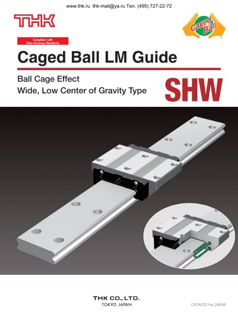
www.thk.ru thk-mail@ya.ru Тел. (495) 727-22-72Compliant withNew Accuracy Standards<strong>Caged</strong> <strong>Ball</strong> <strong>LM</strong> <strong>Guide</strong><strong>Ball</strong> Cage EffectWide, Low Center of Gravity Type<strong>SHW</strong>CATALOG No.248-6E
<strong>Ball</strong> Cage EffectThe early forms of ball bearings were full-ball types without ball cages. Friction between balls caused loudnoise, made high-speed rotation impossible and shortened the service life. Twenty years later, a <strong>Caged</strong> <strong>Ball</strong>design was developed for ball bearings. The new design enabled high-speed rotation at a low noise level,and extended the service life despite the reduced number of balls used. It marked a major development inthe history of ball bearings.Similarly, the quality of needle bearings was significantly improved by the caged needle structure.With cage-less, full-ball types of ball bearings, balls make metallic contact with one another andproduce loud noise. In addition, they rotate in opposite directions, causing the sliding contact between twoadjacent balls to occur at a speed twice the ball-spinning rate. It results in severe wear and shortens theservice life.In addition, without a cage, balls make point contact to increase bearing stress, thus facilitatingbreakage of the oil film. In contrast, each caged ball contacts the cage over a wide area. Therefore, the oilfilm does not break, the noise level is low and balls can rotate at a high speed, resulting in a longservice life.Long Service Life and Long-termMaintenance-free OperationSuperbly High SpeedLow Noise, Acceptable Running SoundSmooth MotionLow Dust Generationwww.thk.ru thk-mail@ya.ru Тел. (495) 727-22-72Rotary ball bearing<strong>Caged</strong> <strong>Ball</strong> <strong>LM</strong> <strong>Guide</strong>Conventional structureAdjacent balls contact each otherat a point. As a result, contactstress is high and the oil filmbreaks due to friction.The service life becomes shorter.<strong>Ball</strong><strong>Caged</strong> <strong>Ball</strong> structureThe service life is prolonged due to the elimination of wear causedby friction between balls.The absence of friction between balls results in reduced heatgeneration during high-speed rotation.The absence of friction between balls eliminates collision noise ofthe balls.The even spacing of the balls enables them to move smoothly.Retention of lubricant in the ball cage ensures a long service life.Oil-film contactWith the <strong>Caged</strong> <strong>Ball</strong> <strong>LM</strong> <strong>Guide</strong>, the use of a ball cageallows lines of evenly spaced balls to circulate, thuseliminating friction between the balls.In addition, grease held in a space between the ballcirculation path and the ball cage (grease pocket) isapplied on the contact surface between each ball andthe ball cage as the ball rotates, forming an oil film onthe ball surface. This minimizes the risk of oil-filmbreak.High bearing stress due toball-to-ball contactConventional structure<strong>Caged</strong> <strong>Ball</strong> structureExtremely low bearing stressachieved with ball-to-cage contact
www.thk.ru thk-mail@ya.ru Тел. (495) 727-22-72Wide, Low Center of Gravity Type<strong>Caged</strong> <strong>Ball</strong> <strong>LM</strong> <strong>Guide</strong><strong>SHW</strong><strong>LM</strong> block<strong>LM</strong> railEndplateEnd seal<strong>Ball</strong><strong>Ball</strong> cageCross sectionStructure of <strong>Model</strong> <strong>SHW</strong><strong>Ball</strong>s roll in four rows of raceways precision-ground on an <strong>LM</strong> rail and an <strong>LM</strong> block, and ball cages andendplates incorporated in the <strong>LM</strong> block allow the balls to circulate.This model is a wide and highly rigid <strong>LM</strong> <strong>Guide</strong> that uses ball cages to achieve low noise, long-termmaintenance-free operation and high speed. Wide, low center of gravity<strong>Model</strong> <strong>SHW</strong>, which has a wide <strong>LM</strong> rail and a low center ofgravity, is optimal for locations requiring space saving andlarge Mc moment rigidity. 4-way equal loadEach row of balls is placed at a contact angle of 45so thatthe rated loads applied to the <strong>LM</strong> block are uniform in thefour directions (radial, reverse-radial and lateral directions),enabling the <strong>LM</strong> <strong>Guide</strong> to be used in all orientations and inextensive applications. Self-adjustment capabilityThe self-adjustment capability through Face-to-Faceconfiguration of THK's unique circular-arc grooves (DF set)enables a mounting error to be absorbed even under apreload, thus achieving highly accurate, smooth linearmotion. Low dust generationUse of ball cages eliminates friction between balls andretains lubricant, thus achieving low dust generation.
www.thk.ru thk-mail@ya.ru Тел. (495) 727-22-72<strong>SHW</strong> Outline<strong>Model</strong> <strong>SHW</strong> - Product OverviewThis model is capable of receiving a large moment with a single rail due to a 4-way equal-load, wide, lowcenter of gravity structure. In addition, the geometrical moment of inertia of the <strong>LM</strong> rail is large and thelateral rigidity is high.Major applications Printed circuit board drilling machine / semiconductor manufacturing machine /electric discharge machine / insertion machine / optical stage<strong>Model</strong> <strong>SHW</strong>-CAThe flange of the <strong>LM</strong> block hastapped holes.It can be mounted from the top orthe bottom.<strong>SHW</strong> 12CAM<strong>SHW</strong> 14CAM<strong>SHW</strong> 17CAM<strong>SHW</strong> 21CA<strong>SHW</strong> 27CA<strong>SHW</strong> 35CA<strong>SHW</strong> 50CA<strong>Model</strong> <strong>SHW</strong>-CRThe <strong>LM</strong> block has tapped holes.<strong>SHW</strong> 12CRM<strong>SHW</strong> 12HRM<strong>SHW</strong> 14CRM<strong>SHW</strong> 17CRM<strong>SHW</strong> 21CR<strong>SHW</strong> 27CR<strong>SHW</strong> 35CR<strong>SHW</strong> 50CR
www.thk.ru thk-mail@ya.ru Тел. (495) 727-22-72<strong>SHW</strong> OUTLINE<strong>Model</strong> <strong>SHW</strong> - Product OverviewRated Loads in All Directions<strong>Model</strong> <strong>SHW</strong> is capable of receivingloads in all four directions: radial,reverse-radial and lateral directions.The basic load ratings are uniform in the fourdirections (radial, reverse-radial and lateraldirections), and their actual values areprovided in the dimensional table* 1 for <strong>SHW</strong>.Reverse-radial directionLateraldirectionRadial directionLateraldirection*1: Dimensional table formodel <strong>SHW</strong><strong>Model</strong> <strong>SHW</strong>-CA pages 9-10<strong>Model</strong> <strong>SHW</strong>-CR/<strong>SHW</strong>-HR pages 11-12Equivalent LoadWhen the <strong>LM</strong> block of model <strong>SHW</strong>receives loads in all directionssimultaneously, the equivalent load isobtained from the equation below.PEPRPLPTPE Equivalent load (N)⋅Radial direction⋅Reverse-radial direction⋅Lateral directionPR Radial load (N)PL Reverse-radial load (N)PT Lateral load (N)
www.thk.ru thk-mail@ya.ru Тел. (495) 727-22-72*1: Basic dynamic load rating(C)It refers to a load with aconstant magnitude anddirection under which thenominal life (L) of a group ofidentical <strong>LM</strong> <strong>Guide</strong> unitsindependently operating is50 km.Service lifeThe service life of an <strong>LM</strong> <strong>Guide</strong> is subject to variations even under the sameoperational conditions. Therefore, it is necessary to use the nominal life definedbelow as a reference value for obtaining the service life of the <strong>LM</strong> <strong>Guide</strong>.Nominal lifeThe nominal life means the total traveldistance that 90% of a group of units of thesame <strong>LM</strong> <strong>Guide</strong> model can achieve withoutflaking (scale-like exfoliation on the metalsurface) after individually running under thesame conditions.Service life timeOnce the nominal life (L) has been obtained,the service life time can be obtained using theequation on the right if the stroke length andthe number of reciprocations are constant.fH · fT · fC CL = ( · ) 3 50fWPCL : Nominal life (km)C : Basic dynamic load rating* 1 (N)PC : Calculated load (N)fH : Hardness factor (see Fig. 1)fT : Temperature factorfC : Contact factor (see Table 1)fW : Load factor (see Table 2)L 10 6Lh =2 RS n1 60Lh : Service life time (h)Rs : Stroke length (mm)n1 : No. of reciprocations per min (min -1 )fHHardness factorTo ensure the achievement of the optimum load capacity of the <strong>LM</strong> <strong>Guide</strong>,the raceway hardness must be between 58 and 64 HRC.At hardness below this range, the basic dynamic and static load ratingsdecrease. Therefore, the rating values must be multiplied by therespective hardness factors (fH).Since the <strong>LM</strong> <strong>Guide</strong> has sufficient hardness, the fH value for the <strong>LM</strong> <strong>Guide</strong>is normally 1.0 unless otherwise specified.Fig. 1 1.00.90.80.70.60.50.40.30.20.1Hardness factor fH60 50 40 30 20 10Raceway hardness (HRC)fCContact factorWhen multiple <strong>LM</strong> blocks are used in close contact with each other, it isdifficult to achieve uniform load distribution due to moment loads andmounting-surface accuracy. When using multiple blocks in close contactwith each other, multiply the basic load rating (C or C0) by thecorresponding contact factor indicated in Table 1.Note: When uneven load distribution is expected in a large machine, consider using a contactfactor from Table 1.Table 1 Contact Factor (fC)Number of blocks used in close contact23456 or greaterNormal useContact factor fC0.810.720.660.610.61fTTemperature factorSince the service temperature of <strong>Caged</strong> <strong>Ball</strong> <strong>LM</strong> <strong>Guide</strong>s is normally 80Cor below, the fT value is 1.0.fWLoad factorIn general, reciprocating machines tend to produce vibrations or impactduring operation. It is especially difficult to accurately determine allvibrations generated during high-speed operation and impacts producedeach time the machine starts and stops. Therefore, where the effects ofspeed and vibration are estimated to be significant, divide the basicdynamic load rating (C) by a load factor selected from Table 2, whichcontains empirically obtained data.FaintWeakMediumStrongTable 2 Load FactorfWVibration/impact Speed (V) fWVery slowV0.25m/sSlow0.25V1m/sMedium1V2m/sFastV2m/s1 to 1.21.2 to 1.51.5 to 22 to 3.5
www.thk.ru thk-mail@ya.ru Тел. (495) 727-22-72<strong>SHW</strong> OUTLINE<strong>Model</strong> <strong>SHW</strong> - Product OverviewRadial Clearance StandardSince the radial clearance of an <strong>LM</strong><strong>Guide</strong> greatly affects the runningaccuracy, load carrying capacity andrigidity of the <strong>LM</strong> <strong>Guide</strong>, it is importantto select an appropriate clearanceaccording to the application.In general, selecting a negative clearance (i.e., apreload* 1 is applied) while taking into accountpossible vibrations and impact generated fromreciprocating motion favorably affects theservice life and the accuracy.Radial clearance*1: PreloadPreload is an internal loadapplied to the rollingelements (balls, rollers,etc.) of an <strong>LM</strong> block inadvance in order toincrease its rigidity.The clearance of all model<strong>SHW</strong> units is adjusted tothe designated value beforebeing shipped. Therefore, itis unnecessary to adjust thepreload.Unit: mIndication symbol Normal Light preload Medium preload<strong>Model</strong> No. No symbol C1 C012–81.5 to 0 –84 to –81.0 ——14–82.0 to 0 –85 to –81.0 ——17–83.0 to 0 –87 to –83.0 ——21–84.0 to +2 –88 to –84.0 ——27–85.0 to +2 –11 to –85.0 ——35–81.0 to +4 –18 to –88.0 –28 to –1850–10.0 to +5 –24 to –10.0 –38 to –24
www.thk.ru thk-mail@ya.ru Тел. (495) 727-22-72*1: Running parallelismIt refers to the parallelismerror between the <strong>LM</strong> blockand the <strong>LM</strong> rail datum planewhen the <strong>LM</strong> block travelsthe whole length of the <strong>LM</strong>rail with the <strong>LM</strong> rail securedon the reference datumplane using bolts.*2: Difference in height MIt indicates the differencebetween the minimum andmaximum values of height(M) of each of the <strong>LM</strong>blocks used on the sameplane in combination.Accuracy StandardThe accuracy of model <strong>SHW</strong> is specified in terms of running parallelism ( *1 ),dimensional tolerance for height and width, and height and width differencebetween a pair ( *2, *3 ) when two or more <strong>LM</strong>blocks are used on one rail or when two ormore rails are mounted on the same plane.The accuracy of model <strong>SHW</strong> is categorized into Normalgrade (no symbol), High-accuracy grade (H), Precision grade (P),Super-precision grade (SP) and Ultra-super-precision grade(UP) by model numbers,as indicated in the table below.*3: Difference in width W2It indicates the differencebetween the minimum andmaximum values of thewidth (W2) between each ofthe <strong>LM</strong> blocks, mounted onone <strong>LM</strong> rail in combination,and the <strong>LM</strong> rail.<strong>Model</strong> No.12141721273550Accuracy standardsItemC AD BC AD BC AD BC AD BNormal gradeNo symbol0.070.0150.040.020.070.020.060.020.080.020.070.0250.080.0250.070.03High-accuracy gradeH0.030.0070.020.01Precision gradeP0.0150.0050.010.006as shown in the table belowas shown in the table belowas shown in the table belowas shown in the table belowSuper precision grade Ultra precision gradeSP0.0070.0030.0070.004UP0000.03– 0.03– 0.015– 0.0080.01 0.006 0.004 0.0030000.03– 0.02– 0.015– 0.0080.01 0.006 0.004 0.0030000.04– 0.04– 0.02– 0.010.015 0.007 0.005 0.0030000.03– 0.03– 0.015– 0.010.015 0.007 0.005 0.003as shown in the table belowas shown in the table below0000.04– 0.05– 0.03– 0.0150.015 0.007 0.005 0.0030000.04– 0.04– 0.025– 0.0150.015 0.007 0.005 0.003as shown in the table belowas shown in the table belowUnit: mm<strong>LM</strong> Rail Length and Running Parallelism by Accuracy of model <strong>SHW</strong>Unit: m<strong>LM</strong> rail length (mm)Running Parallelism ValuesAboveOr lessNormal grade High-accuracy grade Precision grade Super precision grade Ultra precision gradeNo Symbol H P SP UP 50 5 3 2 1.5 150 80 5 3 2 1.5 180 125 5 3 2 1.5 1125 200 5 3.5 2 1.5 1200 250 6 4 2.5 1.5 1250 315 7 4.5 3 1.5 1315 400 8 5 3.5 2 1.5400 500 9 6 4.5 2.5 1.5500 630 11 7 5 3 2630 800 12 8.5 6 3.5 2800 1000 13 9 6.5 4 2.51000 1250 15 11 7.5 4.5 31250 1600 16 12 8 5 41600 2000 18 13 8.5 5.5 4.52000 2500 20 14 9.5 6 52500 3150 21 16 11 6.5 5.53150 4000 23 17 12 7.5 64000 5000 24 18 13 8.5 6.5
Shoulder Height of the Mounting Base and the Corner RadiusNormally, the mounting base for the <strong>LM</strong> rail and the <strong>LM</strong> block has a datum plane onthe side face of the shoulder of the base in order to allow easy installation and highlyaccurate positioning.www.thk.ru thk-mail@ya.ru Тел. (495) 727-22-72<strong>SHW</strong> OUTLINE<strong>Model</strong> <strong>SHW</strong> - Product OverviewThe corner of the mountingshoulder must be machinedto have a recess, ormachined to be smallerthan the corner radius "r," toprevent interference withthe chamfer of the <strong>LM</strong> rail orthe <strong>LM</strong> block.<strong>Model</strong> No.12141721273550Shoulder for the <strong>LM</strong> railCorner radiusr (max)0.50.50.40.40.40.80.8Shoulder for the <strong>LM</strong> blockShoulder heightfor the <strong>LM</strong> railH11.51.52.02.52.53.53.0Shoulder heightfor the <strong>LM</strong> blockH24545556H32.02.02.53.03.04.03.4Unit: mmError Allowance in the Parallelism Between Two RailsThe table shows error allowances in parallelism(P) between two rails that will not affect theservice life in normal operation.<strong>Model</strong> No. Clearance C0 Clearance C1 Normal clearance12141721273550—————202710121518202230Unit: mError Allowance in Vertical Level Between Two Rails13162025253040The values in the table indicate the errorallowance in vertical level(S) between two railsper 500 mm of the axis-to-axis distance, andare proportional to the axis-to-axis distance.Unit: m<strong>Model</strong> No. Clearance C0 Clearance C1 Normal clearance12141721273550—————7090111620858585110405065130130130170
www.thk.ru thk-mail@ya.ru Тел. (495) 727-22-72<strong>Model</strong> <strong>SHW</strong>-CADimensional Table for <strong>Model</strong> <strong>SHW</strong>-CA <strong>Model</strong>s <strong>SHW</strong>12CAM and <strong>SHW</strong>14CAM<strong>Model</strong> No.<strong>SHW</strong> 12CAM<strong>SHW</strong> 14CAM<strong>SHW</strong> 17CAM<strong>SHW</strong> 21CA<strong>SHW</strong> 27CA<strong>SHW</strong> 35CA<strong>SHW</strong> 50CAHeightM12141721273550Outer dimensionsWidthW4050606880120162Length<strong>LM</strong> block dimensionsL B C S H L1 T K N37.045.551.059.072.8107.0141.0354553607010714418242629406080M 3M 3M 4M 5M 6M 8M102.52.53.34.45.36.88.627.034.038.043.656.683.0107.0456810141810.012.014.517.723.531.046.02.83.34.05.06.07.614.0H32.02.02.53.03.04.03.4Symbol M indicates that stainless steel is used in the <strong>LM</strong> block, <strong>LM</strong> rail and balls. Those models marked with this symbol aretherefore highly resistant to corrosion and environment.■ Example of model numbercoding<strong>SHW</strong>17 CA 2 QZ UU C1 M +580L P M -z x c v b n m , . ⁄0 ⁄1z<strong>Model</strong> number xType of <strong>LM</strong> block cNo. of <strong>LM</strong> blocks used on the same rail vWith QZ LubricatorbContamination protection accessory symbol (see page 15) nRadial clearance symbol (see page 6) m<strong>LM</strong> block is made of stainless steel,<strong>LM</strong> rail length (in mm) .Accuracy symbol (see page 7) ⁄0<strong>LM</strong> rail is made of stainless steel ⁄1No. of rails used on the same plane This model number indicates that an <strong>LM</strong> block and an <strong>LM</strong> rail constitute one set (i.e., the required number of sets when 2rails are used in parallel is 2).Those models equipped with QZ Lubricator cannot have a grease nipple.
www.thk.ru thk-mail@ya.ru Тел. (495) 727-22-72 <strong>Model</strong>s <strong>SHW</strong>17CAM and <strong>SHW</strong>21 to 50CAWidthW1 W2 W31824333742699011.013.013.515.519.025.536.0——1822244060Unit: mm<strong>LM</strong> rail dimensions Basic load rating Static permissible moment [kN-m] 2 MassHeightM16.67.58.611.015.019.024.0PitchF40404050608080d1✕d2✕h4.5✕7.5✕5.34.5✕7.5✕5.34.5✕7.5✕5.34.5✕7.5✕5.34.5✕7.5✕5.37✕11✕99✕14✕12LengthMax 11000143018001900300030003000CkN4.317.057.658.2416.0035.5070.20C0kN5.668.9810.1812.8022.7049.2091.40MA1 block0.02280.04660.05910.08060.18700.60301.46002 blocks inclose contact0.1200.2360.2980.4340.9493.0007.370MB1 block0.02280.04660.05910.08060.18700.60301.46002 blocks inclose contact0.1200.2360.2980.4340.9493.0007.370MC1 block0.04050.09040.16400.22900.45501.63003.9700<strong>LM</strong> blockkg0.050.100.150.240.471.403.70<strong>LM</strong> railkg/m0.801.231.902.904.509.6015.00If a grease nipple is required, indicate "with grease nipple;" if a greasing hole is required, indicate "with a tapped hole forgreasing."1 The maximum length under "Length" indicates the standard maximum length of an <strong>LM</strong> rail.2 Static permissible moment: 1 block: static permissible moment value with 1 <strong>LM</strong> blockDouble blocks: static permissible moment value with 2 blocks closely contacting with eachother
www.thk.ru thk-mail@ya.ru Тел. (495) 727-22-72<strong>Model</strong>s <strong>SHW</strong>-CR/<strong>SHW</strong>-HRDimensional Table for <strong>Model</strong>s <strong>SHW</strong>-CR/<strong>SHW</strong>-HRR <strong>Model</strong>s <strong>SHW</strong>27 to 50CR<strong>Model</strong> No.<strong>SHW</strong> 12CRM<strong>SHW</strong> 12HRM<strong>SHW</strong> 14CRM<strong>SHW</strong> 17CRM<strong>SHW</strong> 21CR<strong>SHW</strong> 27CR<strong>SHW</strong> 35CR<strong>SHW</strong> 50CRHeightM1212141721273550Outer dimensionsWidthW303040505462100130Length<strong>LM</strong> block dimensionsL B C S✕R L1 T K N37.050.445.551.059.072.8107.0141.0212128293146761001224151519325065M3✕3.5M3✕3.5M3✕4M4✕5M5✕6M6✕6M8✕8M10✕1527.040.434.038.043.656.683.0107.04456810141810.010.012.014.517.723.531.046.02.82.83.34.05.06.07.614.0H32.02.02.02.53.03.04.03.4Symbol M indicates that stainless steel is used in the <strong>LM</strong> block, <strong>LM</strong> rail and balls. Those models marked with this symbol aretherefore highly resistant to corrosion and environment.■ Example of model numbercoding<strong>SHW</strong>17 CR 2 QZ KKHH C1 M +820L P M -z x c v b n m , . ⁄0 ⁄1z<strong>Model</strong> number xType of <strong>LM</strong> block cNo. of <strong>LM</strong> blocks used on the same rail vWith QZ LubricatorbContamination protection accessory symbol (see page 15) nRadial clearance symbol (see page 6) m<strong>LM</strong> block is made of stainless steel,<strong>LM</strong> rail length (in mm) .Accuracy symbol (see page 7) ⁄0<strong>LM</strong> rail is made of stainless steel ⁄1No. of rails used on the same plane This model number indicates that an <strong>LM</strong> block and an <strong>LM</strong> rail constitute one set (i.e., the required number of sets when 2rails are used in parallel is 2).Those models equipped with QZ Lubricator cannot have a grease nipple.
www.thk.ru thk-mail@ya.ru Тел. (495) 727-22-72 R <strong>Model</strong>s <strong>SHW</strong>12CRM, <strong>SHW</strong>12HRM and <strong>SHW</strong>14CRMR <strong>Model</strong>s <strong>SHW</strong>17CRM and <strong>SHW</strong>21CRWidthW1 W2 W318182433374269906.06.08.08.58.510.015.520.0———1822244060Unit: mm<strong>LM</strong> rail dimensions Basic load rating Static permissible moment [kN-m] 2 MassHeightM16.66.67.58.611.015.019.024.0PitchF4040404050608080d1✕d2✕h4.5✕7.5✕5.34.5✕7.5✕5.34.5✕7.5✕5.34.5✕7.5✕5.34.5✕7.5✕5.34.5✕7.5✕5.37✕11✕99✕14✕12LengthMax 110001000143018001900300030003000CkNC0kNMA1 block2 blocks in4.31 5.66 0.02285.56 8.68 0.05117.05 8.98 0.04667.65 10.18 0.05918.24 12.80 0.080616.00 22.70 0.187035.50 49.20 0.603070.20 91.40 1.4600close contact0.1200.2460.2360.2980.4340.9493.0007.370MB1 block0.02280.05110.04660.05910.08060.18700.60301.46002 blocks inclose contact0.1200.2460.2360.2980.4340.9493.0007.370MC1 block0.04050.06210.09040.16400.22900.45501.63003.9700<strong>LM</strong> blockkg0.040.060.080.130.190.361.203.00<strong>LM</strong> railkg/m0.800.801.231.902.904.509.6015.00If a grease nipple is required, indicate "with grease nipple;" if a greasing hole is required, indicate "with a tapped hole forgreasing."1 The maximum length under "Length" indicates the standard maximum length of an <strong>LM</strong> rail.2 Static permissible moment: 1 block: static permissible moment value with 1 <strong>LM</strong> blockDouble blocks: static permissible moment value with 2 blocks closely contacting with eachother
www.thk.ru thk-mail@ya.ru Тел. (495) 727-22-72<strong>SHW</strong>Standard Length and Maximum Length of the <strong>LM</strong> RailThe table below shows the standard <strong>LM</strong> rail lengths and the maximum lengths of model <strong>SHW</strong>variations. If the maximum length of the desired <strong>LM</strong> rail exceeds them, connected rails will beused. Contact THK for details.For the G dimension when a special length is required, we recommend selecting the corresponding Gvalue from the table. The longer the G dimension is, the less stable the G area may become afterinstallation, thus adversely affecting accuracy.<strong>Model</strong> No.Standard <strong>LM</strong> rail length (L0)Standard pitch F 40G15Max length 1000Standard Length and Maximum Length of the <strong>LM</strong> Rail for <strong>Model</strong> <strong>SHW</strong><strong>SHW</strong> 1270110150190230270310390470<strong>SHW</strong> 147011015019023027031039047055067040151430<strong>SHW</strong> 1711019031047055040151800<strong>SHW</strong> 2113023038048058078050151900<strong>SHW</strong> 2716028034046064082060203000<strong>SHW</strong> 3528044076010001240156080203000Unit: mm<strong>SHW</strong> 50280440760100012401640204080203000Note 1: The maximum length varies with accuracy grades. Contact THK for details.Note 2: If connected rails are not allowed and a greater length than the maximum values above is required, contact THK.Note 3: <strong>Model</strong>s <strong>SHW</strong>12, 14 and 17 are made of stainless steel.
www.thk.ru thk-mail@ya.ru Тел. (495) 727-22-72<strong>SHW</strong> OPTIONSOptionsFor model <strong>SHW</strong>, contamination protection and lubricationaccessories are available. Make a selection according to theapplication and the installation site.7Dedicated bellows J<strong>SHW</strong> for model <strong>SHW</strong>8Dedicated C-cap for <strong>LM</strong> rail mounting holes4Double seals6Metal scraper1End seal5Laminated ContactScraper LaCSInner seal 3Grease nipple 10QZ Lubricator 92Side seal
www.thk.ru thk-mail@ya.ru Тел. (495) 727-22-72Contamination Protection AccessoriesWhen foreign matter enters an <strong>LM</strong> system, it will cause abnormal wear or shorten the service life. It isnecessary to prevent foreign matter from entering the system. Therefore, when possible entrance offoreign matter is predicted, it is important to select an effective sealing device or contaminationprotection device that meets the working conditions.1End sealUsed in locations exposed to dust.End sealSeals and Scrapersz to v SealsHighly wear-resistant end seals made of special resin rubber and sideseals for increased contamination protection effect are available.If desiring a contamination protection accessory, specify it with thecorresponding symbol indicated in table 3.For the supported model numbers for contamination protectionaccessories and the overall <strong>LM</strong> block length with a contaminationprotection accessory attached (dimension L), see table 4.2Side sealSide sealUsed in locations where dust mayenter the <strong>LM</strong> block from the side orbottom surface, such as vertical,horizontal and inverted mounts.Seal resistance valueFor the maximum seal resistancevalue per <strong>LM</strong> block when a lubricantis applied on seals <strong>SHW</strong> … UU/SS,refer to the corresponding valueprovided in table 1.Table 1 Maximum Seal Resistance Valueof Seals <strong>SHW</strong> … UU/SS Unit: N<strong>Model</strong> No.Seal resistance valueUU SS12CA/CR 1.0 1.412HR 1.0 1.8141.2 1.8171.4 2.2214.9 6.9274.9 8.9359.8 15.850 14.7 22.734Inner sealUsed in locations severely exposedto dust or cutting chips.Inner sealDouble sealsUsed in locations exposed to muchdust or many cutting chips.End sealbn ScrapersLaminated Contact Scraper LaCS®For locations with an even more adverse working conditions, theLaminated Contact Scraper LaCS is available. LaCS preventsminute foreign matter from entering the <strong>LM</strong> block by removingsuch foreign matter adhering to the <strong>LM</strong> rail in multiple stagesthrough a laminated contact structure (3-layered scraper).FeaturesSince the 3 layers of scrapers fullycontact the <strong>LM</strong> rail, LaCS is highlycapable of removing minute foreignmatter.Since it uses oil-impregnated, foamsynthetic rubber with a selflubricatingfunction, low frictionresistance is achieved.Basic Specifications of LaCS1 Service temperature range ofLaCS: -20 C to +80 C2 Resistance of LaCS: indicated intable 2*Note that LaCS is not sold alone.Table 2 Resistance of LaCSUnit: N<strong>Model</strong> No. Resistance of LaCS213.9276.53513.05019.5Note 1: Each resistance value in the tableonly consists of that of LaCS, anddoes not include slidingresistances of seals and otheraccessories.Note 2: For the maximum service speedof LaCS, contact THK.
www.thk.ru thk-mail@ya.ru Тел. (495) 727-22-72OPTIONSOptionsTable 3 Symbols of Contamination Protection Accessories for <strong>Model</strong> <strong>SHW</strong>SymbolUUSSDDZZKKSSHHDDHHZZHHKKHHContamination protection accessoryWith end sealWith end seal + side seal + inner sealWith double seals + side seal + inner sealWith end seal + side seal + inner seal + metal scraperWith double seals + side seal + inner seal + metal scraperWith end seal + side seal + inner seal + LaCSWith double seals + side seal + inner seal + LaCSWith end seal + side seal + inner seal + metal scraper + LaCSWith double seals + side seal + inner seal + metal scraper + LaCSNote: The inner seal and LaCS are not available for models <strong>SHW</strong>12, 14 and 17.Table 4 Overall <strong>LM</strong> Block Length (Dimension L) of <strong>Model</strong> <strong>SHW</strong> with aContamination Protection Accessory AttachedUnit: mm<strong>Model</strong> No. UU SS DD ZZ KK SSHH DDHH ZZHH KKHH12 CAM/CRM 37.0 37.0 — — — 48.0 — — —12 HRM50.4 50.4 — — — 61.4 — — —14 CAM/CRM 45.5 45.5 — — — 60.7 — — —17 CAM/CRM 51.0 51.0 54.0 53.4 56.4 66.2 69.2 67.4 70.421 CA/CR59.0 59.0 64.0 63.2 68.2 75.6 80.6 77.2 82.227 CA/CR72.8 72.8 78.6 77.8 83.6 89.4 95.2 91.8 97.635 CA/CR 107.0 107.0 114.4 112.0 119.4 129.0 136.4 131.4 138.850 CA/CR 141.0 141.0 149.2 147.4 155.6 166.0 174.2 168.4 176.6Note: "—" indicates not available.LaCSUsed in harsh environments exposedto foreign matter such as fine dust andliquids. <strong>Ball</strong> cage<strong>Ball</strong> Contact scraperStructural drawingLiquidMetal scraperUsed in locations where weldingspatter may adhere to the <strong>LM</strong> rail.Metal scraper5Large amount offoreign matter6m Dedicated Bellows J<strong>SHW</strong> for <strong>Model</strong> <strong>SHW</strong>For locations with an even more adverse working conditions,dedicated bellows are available. The dimensions of thededicated bellows are provided below. When placing an order,specify the desired bellows type with the corresponding bellowsmodel number indicated below.Dimensional Table for J<strong>SHW</strong>Main dimensions(mm)<strong>Model</strong> No.W H H1 P1 P2 b1 t1 b2 t2J<strong>SHW</strong> 17J<strong>SHW</strong> 21J<strong>SHW</strong> 27J<strong>SHW</strong> 35J<strong>SHW</strong> 50<strong>Model</strong> No.J<strong>SHW</strong> 17J<strong>SHW</strong> 21J<strong>SHW</strong> 27J<strong>SHW</strong> 35J<strong>SHW</strong> 5068758512016422.025.033.535.042.023.026.033.535.042.0151720202015.417.020.020.020.0■ Example of model numbercoding39.035.825.075.089.42.62.93.57.514.0Note 1: When desiring to use the dedicated bellows other than in horizontal mount (i.e., vertical,wall and inverted mount), or when desiring a heat-resistant type of bellows, contact THK.Note 2: For lubrication when using the dedicated bellows, contact THK.Note 3: For the mounting bolts marked with "*", use tapping screws.Note 4: When using the dedicated bellows, the <strong>LM</strong> block and <strong>LM</strong> rail need to be machined so thatthe bellows can be mounted. Be sure to indicate that the dedicated bellows is requiredwhen ordering SHS.J<strong>SHW</strong>21-60/360z<strong>Model</strong> number bellows for <strong>SHW</strong>21xBellows dimensions (length when compressed / length when extended)1822204050z67101316Other dimensions(mm)Mounting bolt a bS* S1 Type CA Type CRM2.0✕ 4RM2.0✕ 5RM2.6✕ 6RM3.0✕ 8RM4.0✕12RM3✕6RM3✕6RM3✕6RM3✕6RM4✕8R88106—4.03.52.50.01.09.010.511.510.017.0Supportedmodel<strong>SHW</strong> 17<strong>SHW</strong> 21<strong>SHW</strong> 27<strong>SHW</strong> 35<strong>SHW</strong> 50ALmaxLmin56777xDedicated bellows J<strong>SHW</strong>for model <strong>SHW</strong>Used in locations exposed todust or cutting chips.SLmin SStroke length (mm)(A1)Lmax LminAAExtension rateNote: The length of the bellows iscalculated as follows.7
www.thk.ru thk-mail@ya.ru Тел. (495) 727-22-7285Lubrication Accessories9Dedicated C-capIt prevents cutting chips fromentering the <strong>LM</strong> rail mountingholes.QZ Lubricator, Dedicated C-cap for <strong>LM</strong> Rail Mounting HolesIf any of the <strong>LM</strong> rail mounting holes of an <strong>LM</strong> <strong>Guide</strong> is filled with cuttingchips or foreign matter, they may enter the <strong>LM</strong> block structure.Entrance of such foreign matter can be prevented by covering each <strong>LM</strong>rail mounting hole with the dedicated cap so that the top of themounting holes are on the same level as the <strong>LM</strong> rail top face.The dedicated C-cap for <strong>LM</strong> rail mounting holes is highly durable sinceit uses a special synthetic resin with high oil resistance and high wearresistance. When placingan order, specify thedesired cap type with thecorresponding capnumber indicated in thetable on the right.. QZ LubricatorTMC-cap<strong>Model</strong> No.model No.12141721273550Main dimensions mmBolt usedD HC4 M4 7.8 1.0C4 M4 7.8 1.0C4 M4 7.8 1.0C4 M4 7.8 1.0C4 M4 7.8 1.0C6 M6 11.4 2.7C8 M8 14.4 3.7CaseHeavy oil-impregnated fiber netEnd sealHigh-density fiber net<strong>Ball</strong>The QZ Lubricator feeds the right amount of lubricant to the ballraceway on the <strong>LM</strong> rail. This allows an oil film to continuously beformed between the balls and the raceway, and drasticallyextends the lubrication and maintenance intervals.When the QZ Lubricator is required, specify the desired type with thecorresponding symbol indicated in table 1. For supported <strong>LM</strong> <strong>Guide</strong>model numbers for the QZ Lubricator and overall <strong>LM</strong> block length with theQZ Lubricator attached (dimension L), see table 2.FeaturesSupplements lost oil todrastically extend thelubrication/maintenanceinterval.Eco-friendly lubrication systemthat does not contaminate thesurrounding area since it feedsthe right amount of lubricant tothe ball raceway.The user can select a type oflubricant that meets theintended use.Significant Extensionof the MaintenanceIntervalAttaching the QZ Lubricator helpsextend the maintenance intervalthroughout the whole load rangefrom the light-load area to theheavy-load area.Oil control plateFlow of lubricant<strong>Ball</strong> cage*Note that the QZ Lubricator is not sold alone.*Those models equipped with the QZ Lubricator cannot have a grease nipple. When desiring boththe QZ Lubricator and a grease nipple to be attached, contact THK .Table 1 Parts Symbols for <strong>Model</strong> <strong>SHW</strong> with the QZ Lubricator AttachedSymbolQZUUQZSSQZDDQZZZQZKKQZSSHHQZDDHHQZZZHHQZKKHHContamination protection accessories for <strong>LM</strong> <strong>Guide</strong> with QZ Lubricator attachedWith end seal + QZ LubricatorWith end seal + side seal + inner seal + QZ LubricatorWith double seals + side seal + inner seal + QZ LubricatorWith end seal + side seal + inner seal + metal scraper + QZ LubricatorWith double seals + side seal + inner seal + metal scraper + QZ LubricatorWith end seal + side seal + inner seal + LaCS + QZ LubricatorWith double seals + side seal + inner seal + LaCS + QZ LubricatorWith end seal + side seal + inner seal + metal scraper + LaCS + QZ LubricatorWith double seals + side seal + inner seal + metal scraper + LaCS + QZ LubricatorNote: The inner seal and LaCS are not available for models <strong>SHW</strong>12, 14 and 17.
www.thk.ru thk-mail@ya.ru Тел. (495) 727-22-72OPTIONSOptionsTable 2 Overall <strong>LM</strong> Block Length (Dimension L) of <strong>Model</strong> <strong>SHW</strong> withthe QZ Lubricator AttachedUnit: mm<strong>Model</strong> No. QZUU QZSS QZDD QZZZ QZKK QZSSHH QZDDHH QZZZHH QZKKHH12 CAM/CRM 47.0 47.0 — — — 58 — — —12 HRM60.4 60.4 — — — 71.4 — — —14 CAM/CRM 55.5 55.5 — — — 70.7 — — —17 CAM/CRM 63.0 63.0 66.0 65.4 68.4 78.2 81.2 79.4 82.421 CA/CR75.0 75.0 80.0 78.6 83.6 91.6 96.6 93.2 98.227 CA/CR92.8 92.8 98.6 97.2 103 109.4 115.2 111.8 117.635 CA/CR 127.0 127.0 134.4 132.0 139.4 149.0 156.4 151.4 158.850 CA/CR 161.0 161.0 169.2 167.4 175.6 186.0 194.2 188.4 196.6Note: "" indicates not available.The structure of the QZ Lubricatorconsists of three major components: a heavy oil-impregnated fiber net(functions to store lubricant). a high-density fiber net(functions to apply lubricant to theraceway). an oil-control plate(functions to adjust oil flow).The lubricant contained in the QZLubricator is fed by the capillaryphenomenon, which is used also infelt pens and many other products,as the fundamental principle.⁄0 Grease Nipple and Greasing HoleGrease nipple10<strong>Model</strong> <strong>SHW</strong> does not have a grease nipple as standard. For thelocation for attaching the grease nipple, see Fig. 1. Note thatattaching the grease nipple will increase the overall <strong>LM</strong> rail length.The installation of a grease nipple and the drilling of a greasinghole are performed at THK. When ordering <strong>SHW</strong>, indicate that thedesired model requires a grease nipple or greasing hole (forgreasing hole dimensions, supported <strong>LM</strong> <strong>Guide</strong> model numbers forgrease nipples and incremental dimensions, see table 1).End sealEnd sealNote 1: The grease nipple is not available for models <strong>SHW</strong>12, 14 and 17. They can have agreasing hole.Note 2: Using a greasing hole other than for greasing may cause damage.When ContaminationProtection AccessoriesSSHH, DDHH, ZZHH orKKHH are AttachedWhen contamination protectionaccessories SSHH, DDHH,ZZHH or KKHH are attached,the grease nipple is in thelocation indicated in Fig. on theright. Table 2 showsincremental dimensions withthe grease nipple.When ContaminaionProtection Accessories UUor SS are AttachedFor the incremental dimensionof the grease nipple whencontamination protectionaccessories UU or SS areattached, see table 1.When ContaminationProtection Accessories DD,ZZ or KK are AttachedFor the mounting location ofthe grease nipple and itsincremental dimension whencontamination protectionaccessories DD, ZZ or KK areattached, contact THK.LaCSEndplateGrease nippleNote: When desiring the mounting location for thegrease nipple other than the one indicated in Fig.above, contact THK.Table 2 Incremental Dimension withGrease Nipple<strong>Model</strong> No.21CA/CR27CA/CR35CA/CR50CA/CRIncremental dimensionwith grease nippleE4.210.710.021.0EUnit: mmNipple typePB1021BB-M6FB-M6FB-PT1/8Note: For the dimension L, see the correspondingdimension tablepages 9 to 12.Fig1 Location for mounting the greasenippleTable 1 Table of Grease Nippleand Greasing Hole DimensionsUnit: mm<strong>Model</strong> No.12141721273550E——55.5121216Grease nipple or greasing hole2.2 drilled hole2.2 drilled holePB107PB1021BB-M6FB-M6FB-PT1/8
www.thk.ru thk-mail@ya.ru Тел. (495) 727-22-72 Handling<strong>Caged</strong> <strong>Ball</strong> <strong>LM</strong> <strong>Guide</strong> <strong>Model</strong> <strong>SHW</strong>Precautions on useMost models of this product are heavy articles (20 kg or heavier). When carrying the product, two or more people must hold it orconveyance equipment must be used. Failure to do so may cause personal injury or damage to the product.Disassembling components may cause dust to enter the system or degrade mounting accuracy of parts. Do not disassemble theproduct.Tilting an <strong>LM</strong> block or <strong>LM</strong> rail may cause them to fall by their own weight.Dropping or hitting the <strong>LM</strong> <strong>Guide</strong> may damage it. Giving an impact to the <strong>LM</strong> <strong>Guide</strong> could also cause damage to its function even ifthe guide looks intact. LubricationThoroughly remove anti-corrosion oil and feed lubricant before using the product.Do not mix lubricants of different physical properties.In locations exposed to constant vibrations or in special environments such as clean rooms, vacuum and low/high temperature,normal lubricants may not be used. Contact THK for details.When planning to use a special lubricant, contact THK before using it.When adopting oil lubrication, the lubricant may not be distributed throughout the <strong>LM</strong> system depending on the mounting orientationof the system. Contact THK for details.Lubrication interval varies according to the service conditions. Contact THK for details. Precautions on UseEntrance of foreign matter may cause damage to the ball circulating path or functional loss. Prevent foreign matter, such as dust orcutting chips, from entering the system.When planning to use the <strong>LM</strong> system in an environment where coolant penetrates the <strong>LM</strong> block, it may cause trouble to productfunctions depending on the type of coolant. Contact THK for details.Do not use the <strong>LM</strong> system at temperature of 80 or higher. When desiring to use the system at temperature of 80 or higher,contact THK in advance.If foreign matter adheres to the <strong>LM</strong> system, replenish the lubricant after cleaning the product. For available types of detergent,contact THK .When using the <strong>LM</strong> <strong>Guide</strong> with an inverted mount, breakage of the endplate due to an accident or the like may cause balls to fallout and the <strong>LM</strong> block to come off from the <strong>LM</strong> rail and fall. In these cases, take preventive measures such as adding a safetymechanism for preventing such falls.When using the <strong>LM</strong> system in locations exposed to constant vibrations or in special environments such as clean rooms, vacuumand low/high temperature, contact THK in advance.When removing the <strong>LM</strong> block from the <strong>LM</strong> rail and then replacing the block, an <strong>LM</strong> block mounting/removing jig that facilitates suchinstallation is available. Contact THK for details. StorageWhen storing the <strong>LM</strong> <strong>Guide</strong>, enclose it in a package designated by THK and store it in a horizontal orientation while avoiding hightemperature, low temperature and high humidity.● “<strong>LM</strong> <strong>Guide</strong>,” “<strong>Caged</strong> <strong>Ball</strong>,” and “” are registered trademarks of THK CO., LTD.● The photo may differ slightly in appearance from the actual product.● The appearance and specifications of the product are subject to change without notice. Contact THK before placing an order.● Although great care has been taken in the production of this catalog, THK will not take any responsibility for damage resulting from typographical errors or omissions.● For the export of our products or technologies and for the sale for exports, THK in principle complies with the foreign exchange law and the Foreign Exchangeand Foreign Trade Control Law as well as other relevant laws.All rights reservedFor export of THK products as single items, contact THK in advance.NORTH AMERICATHK America,Inc.HEADQUARTERSPhone:+1-847-310-1111 Fax:+1-847-310-1271CHICAGO OFFICEPhone:+1-847-310-1111 Fax:+1-847-310-1182NEW YORK OFFICEPhone:+1-845-369-4035 Fax:+1-845-369-4909ATLANTA OFFICEPhone:+1-770-840-7990 Fax:+1-770-840-7897LOS ANGELES OFFICEPhone:+1-949-955-3145 Fax:+1-949-955-3149SAN FRANCISCO OFFICEPhone:+1-925-455-8948 Fax:+1-925-455-8965BOSTON OFFICEPhone:+1-781-575-1151 Fax:+1-781-575-9295DETROIT OFFICEPhone:+1-248-858-9330 Fax:+1-248-858-9455TORONTO OFFICEPhone:+1-905-820-7800 Fax:+1-905-820-7811SOUTH AMERICATHK Brasil LTDAPhone:+55-11-3767-0100 Fax:+55-11-3767-0101EUROPETHK GmbHEUROPEAN HEADQUARTERSPhone:+49-2102-7425-0 Fax:+49-2102-7425-217HEAD OFFICE 3-11-6, NISHI-GOTANDA, SHINAGAWA-KU, TOKYO 141-8503 JAPANINTERNATIONAL SALES DEPARTMENT PHONE:+81-3-5434-0351 FAX:+81-3-5434-0353Global site : http://www.thk.com/DÜSSELDORF OFFICEPhone:+49-2102-7425-0 Fax:+49-2102-7425-299FRANKFURT OFFICEPhone:+49-2102-7425-650 Fax:+49-2102-7425-699STUTTGART OFFICEPhone:+49-7150-9199-0 Fax:+49-7150-9199-888MÜNCHEN OFFICEPhone:+49-8937-0616-0 Fax:+49-8937-0616-26U.K. OFFICEPhone:+44-1908-30-3050 Fax:+44-1908-30-3070ITALY MILANO OFFICEPhone:+39-039-284-2079 Fax:+39-039-284-2527ITALY BOLOGNA OFFICEPhone:+39-051-641-2211 Fax:+39-051-641-2230SWEDEN OFFICEPhone:+46-8-445-7630 Fax:+46-8-445-7639AUSTRIA OFFICEPhone:+43-7229-51400 Fax:+43-7229-51400-79SPAIN OFFICEPhone:+34-93-652-5740 Fax:+34-93-652-5746TURKEY OFFICEPhone:+90-216-362-4050 Fax:+90-216-569-7150THK France S.A.S.Phone:+33-4-3749-1400 Fax:+33-4-3749-1401CHINATHK (CHINA) CO.,LTD.HEADQUARTERSPhone:+86-411-8733-7111 Fax:+86-411-8733-7000SHANGHAI OFFICEPhone:+86-21-6219-3000 Fax:+86-21-6219-9890BEIJING OFFICEPhone:+86-10-8441-7277 Fax:+86-10-6590-3557CHENGDU OFFICEPhone:+86-28-8526-8025 Fax:+86-28-8525-6357GUANGZHOU OFFICEPhone:+86-20-8333-9770 Fax:+86-20-8333-9726THK (SHANGHAI) CO.,LTD.Phone:+86-21-6275-5280 Fax:+86-21-6219-9890TAIWANTHK TAIWAN CO.,LTD.TAIPEI HEAD OFFICEPhone:+886-2-2888-3818 Fax:+886-2-2888-3819TAICHUNG OFFICEPhone:+886-4-2359-1505 Fax:+886-4-2359-1506TAINAN OFFICEPhone:+886-6-289-7668 Fax:+886-6-289-7669KOREASEOUL REPRESENTATIVE OFFICEPhone:+82-2-3468-4351 Fax:+82-2-3468-4353SINGAPORETHK <strong>LM</strong> SYSTEM Pte. Ltd.Phone:+65-6884-5500 Fax:+65-6884-5550INDIABANGALORE REPRESENTATIVE OFFICEPhone:+91-80-2330-1524 Fax:+91-80-2314-8226©THK CO., LTD.20080103 E4 Printed in Japan