
You also want an ePaper? Increase the reach of your titles
YUMPU automatically turns print PDFs into web optimized ePapers that Google loves.
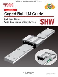
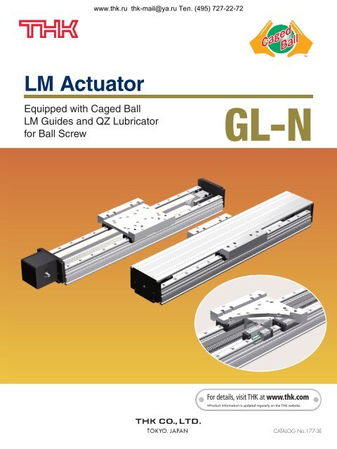
www.thk.ru thk-mail@ya.ru Тел. (495) 727-22-72<strong>LM</strong> <strong>Actuator</strong>Equipped with Caged Ball<strong>LM</strong> Guides and QZ Lubricatorfor Ball Screw<strong>GL</strong>-NFor details, visit THK at www.thk.comProduct information is updated regularly on the THK website.CATALOG No.177-3E
Structures of <strong>LM</strong> <strong>Actuator</strong> <strong>GL</strong>-N ModelBall Screwwww.thk.ru thk-mail@ya.ru Тел. (495) 727-22-72CoverNut bracketSupport unitTableSupport unitAluminum baseCaged Ball <strong>LM</strong> GuideEnd plateBall ScrewFigure 1 Ball Screw Type StructureTiming BeltCoverTiming beltBelt mounting plateTableEnd plateHousingAluminum baseTiming pulley & pulley mounting bracketCaged Ball <strong>LM</strong> GuideFigure 2 Timing Belt Type Structure
Features of <strong>LM</strong> <strong>Actuator</strong> <strong>GL</strong>-N ModelLightweight, high rigidity aluminum base with Caged Ball <strong>LM</strong> Guides has been utilized for the guide portion. A screw orbelt options are available for the drive system.In addition, Caged Ball <strong>LM</strong> Guides and QZ Lubricator for the Ball Screw has been utilized to provide a long-termmaintenance free actuator.Utilizing Caged Ball <strong>LM</strong> Guide (SSR, SHS)SSR model: Due to its 90-degree ball contact structure, is best suited to horizontal applications with relatively lowmoment loads.SHS model: It can handle loads from all directions (radial, reverse radial, and horizontal) with its 4-way equal loadrating capability.Drive System[Ball Screw Type]Variety of screw leads can be selected.www.thk.ru thk-mail@ya.ru Тел. (495) 727-22-72Table 1 Ball Screw Leads by Model Numbers (Rolled ball screw)Model numberBall Screw lead (mm)<strong>GL</strong>15N 5, 10, 16, 20, 30<strong>GL</strong>20N 5, 10, 20, 40Note: For wrap-around motor types, three motor directions (left, right and bottom) can be selected. (See page 4 for details.)[Timing Belt Type]Highly rigid timing belt ensures that high speed processes arepossible for longer stroke (max. 2720 mm) applications than the BallScrew driven type.Table 2 Pitch Diameter of the Timing PulleyModel numberPitch diameter(mm)Slider move distanceper pulley rotation (mm)<strong>GL</strong>15N 35.01 35.01χπ 110<strong>GL</strong>20N 38.20 38.20χπ 120Note: Because the timing pulley has a large pitch diameter, the use of a reducer isrecommended. For details, see pages 18 and 19.PulleySlider1 rotationTravel distanceFigure 3 Slider move distance perpulley rotationLightweight and High RigidityBy using a hollow aluminum extrusion, lightweight and high rigidity is achieved.Table 3 Geometrical Moment of Inertia and Weight in the BaseModel numberGeometrical Moment of Inertia WeightlX (mm 4 ) lY (mm 4 ) (kg/m)<strong>GL</strong>15N 1.61×10 5 2.47×10 6 4.85<strong>GL</strong>20N 3.15×10 5 4.28×10 6 6.47 ** The weight of the SSR model is 6.69kg/m.Y axisCenter of gravityX axisFigure 4 Base Section
www.thk.ru thk-mail@ya.ru Тел. (495) 727-22-72<strong>GL</strong>-N Model also available with optional QZ LubricatorA Caged Ball <strong>LM</strong> Guide and QZ Lubricator for the Ball Screw have been utilized to ensure a long-term maintenancefreeactuator.Ensuring Adaptability with Most Advanced MotorsA wide variety of end plates (motor mounting plates, motor brackets, reducers) are available to be attached to motorswith the latest control technologies. As well as, motors with features applicable for Model <strong>GL</strong>-N. (See pages 16 to 19.)Multiple Options AvailableMultiple options such as covers, bellows, sensors and cable carriers are available.Height Dimensions Standardized with Model <strong>GL</strong>With the same height dimensions as Model <strong>GL</strong> using the conventional full-ball type Model GSR, replacing with themaintenance-free actuator Model <strong>GL</strong>-N using Caged Ball <strong>LM</strong> Guide is possible.1541542723.675.675.69011690116<strong>GL</strong>15<strong>GL</strong>15NFigure 5 Cross-section comparative views18018035.531.59090100130100130<strong>GL</strong>20<strong>GL</strong>20NFigure 6 Cross-section comparative views
Types and FeaturesTypes of Drive Systems[Ball Screw Drive]Direct Mountingwww.thk.ru thk-mail@ya.ru Тел. (495) 727-22-72MotorRequires Servo Coupling to connect the ball screw shaft with input motor shaft.Lateral wrap-around OptionBottom wrap-around OptionR2: Left side motor wrapMotorMotorR1: Right side motor wrap Motor R3: Bottom wrap-aroundAxial dimensions are kept to minimum by applying theWrap-Around option.(Pulley ratio: 1:1)When horizontal space is at a minimum, the bottomside Wrap-Around option is available.(Pulley ratio: 1:1)[Timing Belt Type]Horizontal MountingTiming pulleyNote 1: Please mount Model <strong>GL</strong>-N horizontally. Contact THK if Model <strong>GL</strong>-N will be mounted on a wall.Note 2: Please note that Model <strong>GL</strong>-N with timing belts cannot be mounted vertically.
Specificationwww.thk.ru thk-mail@ya.ru Тел. (495) 727-22-72Model number <strong>GL</strong>15N <strong>GL</strong>20NDrive system Ball Screw Belt Ball Screw BeltScrew lead (mm) 5 10 16 20 30 – 5 10 20 40 –Pulley pitch diameter (mm) – 35.01 – 38.20Repeatability Note 1) (mm) ±0.02 ±0.08 ±0.02 ±0.08Effective stroke Note 2) (mm) 100 to 1200 50 to 1700 200 to 1550 150 to 2700Maximum load capacityguideline Note 3) Note 4) Static permissibleload Note 5) Static permissiblemoment Note 6) [kg][N][N-m]200WHorizontal 60 60 50 45 20 30 – – – – –Vertical 20 16 10 10 3 – – – – – –400WHorizontal – – – – – – 70 70 60 15 50Vertical – – – – – – 30 30 13 6 –Reverse radialdirection9600 14300Horizontal direction 2900 4500Axial direction 2100 – 2200 –MA 430 710MB 240 430MC 610 1020Note 1: This repeatability is ensured at an ambient temperature of 20°C.Note 2: The effective stroke decreases depending on the table length. See the dimensional drawings (pages 7 to 14) for stroke details.Note 3: Maximum load capacity guideline is determined based on rated revolution of the motor at the acceleration of 0.3G.The motor capacity assumes the use of an AC servomotor.Note 4: Values for the belt drive type are guidelines when using 1/5 reducers.Note 5: The static permissible load is determined by the bolt joint strength, and the static rated load of the <strong>LM</strong> guide unit, ball screw unit and the support bearing.For safety purposes, please take into consideration that the strength of the actuator mounting unit is not included.Note 6: The static permissible moment is the maximum value of the moment in each direction.For details on fatigue life, see "Service Life Time and Static Safety Factor" on pages 25 to 26.MA : Pitching directionMB : Yawing directionFigure 7 Directions of static permissible momentMC : Rolling directionTypes of TablesS type: Short table (applicable <strong>LM</strong> Guide model number: SSR-XV)A short table length ensures a longer stroke.L type: Long table (applicable <strong>LM</strong> Guide model number: SSR-XW, and SHS-V)This table is suitable for mounting large sized objects or if the load is off center.L-QZ type: Long table with an <strong>LM</strong> Guide QZ Lubricator (applicable <strong>LM</strong> Guide model numbers: SSR-XWQZand SHS-VQZ)The <strong>LM</strong> Guide is provided with a QZ Lubricator. (This table is longer than the L-type table. See dimensionaldrawings for more details.)Maximum Travel Speed of the <strong>LM</strong> <strong>Actuator</strong>Ball Screw TypeBall Screws have an allowablerotational speed based on the DNvalue and the critical speed.The table travel speed (mm/s) of theL M A c t u a t o r d e p e n d s o n t h erotational speed of the Ball Screwand the rated rpm (3000 min -1 ) of theAC servo motor.Timing Belt TypeThe table shown below summarizes the table travel speed(mm/s) of when the <strong>LM</strong> <strong>Actuator</strong> is equipped with areducer and the AC servo motor is operated at a ratedrpm (3000min -1 ).Maximum travel speedUnit: mm/sNominal model number <strong>GL</strong>15N <strong>GL</strong>20NBall Screw lead 5 10 16 20 30 5 10 20 40340 248 500 800 1000 1500 – – – –460 248 500 800 1000 1500 202 500 1000 2000580 248 500 800 1000 1500 202 500 1000 2000700 248 500 800 1000 1500 202 500 1000 2000Base 820 248 500 800 1000 1500 202 500 1000 2000length 1060 207 391 685 776 1175 202 396 1000 20001240 144 271 474 540 815 185 275 763 15331420 105 198 349 396 595 136 201 560 11201600 – – – – – 104 – 426 8601780 – – – – – 82 – 336 673Note: The <strong>LM</strong> actuator may not reach the maximum travel speed if the moving distance is short.Maximum travel speedUnit: mm/sNominal model number <strong>GL</strong>15N <strong>GL</strong>20NReduction ratio 1/3 1/5 1/9 1/3 1/5 1/9Maximum travelspeed1833 1100 611 2000 1200 667
4444Ball Screw Driven Dimensions<strong>GL</strong>15N Model, Ball Screw Driven[Direct Mounting Specification]www.thk.ru thk-mail@ya.ru Тел. (495) 727-22-724-M6 THRU with thread inserts 2Dcø8h715140(25)dMechanical stroke/2Table length: aMechanical stroke/2(25)b 102-M3 depth 6A1259.1Base length: L12154170.514.32 36455.8119011623.675.6CB611Detailed view of B2.5 1.5Detailed view of CView of AUnit: mmTable type Table length: a b c dS type 126 38 90 53L type 154 52 90 39L(QZ) type 154 52 90 48L-QZ type 180 65 120 21Mechanicalstroke [mm]Main unitweight [kg]Base length: L [mm] 340 460 580 700 820 1060 1240 1420TableTableS type 136 256 376 496 616 856 1036 1216L type 122 242 362 482 602 842 1022 1202L(QZ) type 113 233 353 473 593 833 1013 1193L-QZ type 114 234 354 474 594 834 1014 1194S type 5.8 6.9 8.0 9.2 10.3 12.5 14.2 15.9L type (SSR15XW) 6.1 7.2 8.3 9.5 10.6 12.8 14.5 16.2L type (SHS15V) 6.5 7.6 8.8 9.9 11.1 13.4 15.1 16.8Note 1: The main unit weight includes the cover weight.Note 2: The table L(QZ) type shows a QZ specification only for the Ball Screw.Note 3: The main unit weight of the QZ type is the main unit weight of the table +0.1kg.
ø38.2www.thk.ru thk-mail@ya.ru Тел. (495) 727-22-72<strong>GL</strong>15N Model, Ball Screw Driven[Lateral Wrap-around Specification]BC3.734.319.975.64-M6 THRU with thread inserts 2Dc942551401169015414068(70.6)dMechanical stroke/2Table length: a Mechanical stroke/2 (25)14.311b102-M3 depth 611645710.55.82.5 1.5Detailed view of BDetailed view of C5359.1Base length: L12Unit: mmTable type Table length: a b c dS type 126 38 90 53L type 154 52 90 39L(QZ) type 154 52 90 48L-QZ type 180 65 120 21Mechanicalstroke [mm]Main unitweight [kg]Base length: L [mm] 340 460 580 700 820 1060 1240 1420TableTableS type 136 256 376 496 616 856 1036 1216L type 122 242 362 482 602 842 1022 1202L(QZ) type 113 233 353 473 593 833 1013 1193L-QZ type 114 234 354 474 594 834 1014 1194S type 7.4 8.5 9.6 10.8 11.9 14.1 15.8 17.5L type (SSR15XW) 7.7 8.8 9.9 11.1 12.2 14.4 16.1 17.8L type (SHS15V) 8.1 9.2 10.4 11.5 12.7 15.0 16.7 18.4Note 1: The main unit weight includes the cover weight.Note 2: The table L(QZ) type shows a QZ specification only for the Ball Screw.Note 3: The main unit weight of the QZ type is the main unit weight of the table +0.1kg.
www.thk.ru thk-mail@ya.ru Тел. (495) 727-22-72<strong>GL</strong>15N Model, Ball Screw Driven[Bottom Wrap-around Specification]4-M6 THRU with thread inserts 2DcCB174.30.59445115.8140Base length: L53 12154d Mechanical stroke/2Table length: aMechanical stroke/2 (25)b102-M3 depth 611523.6ø38.2(136)75.659.1161.52.511(85)68Detailed view of BDetailed view of C90Unit: mmTable type Table length: a b c dS type 126 38 90 53L type 154 52 90 39L(QZ) type 154 52 90 48L-QZ type 180 65 120 21Mechanicalstroke [mm]Main unitweight [kg]Base length: L [mm] 340 460 580 700 820 1060 1240 1420TableTableS type 136 256 376 496 616 856 1036 1216L type 122 242 362 482 602 842 1022 1202L(QZ) type 113 233 353 473 593 833 1013 1193L-QZ type 114 234 354 474 594 834 1014 1194S type 7.4 8.5 9.6 10.8 11.9 14.1 15.8 17.5L type (SSR15XW) 7.7 8.8 9.9 11.1 12.2 14.4 16.1 17.8L type (SHS15V) 8.1 9.2 10.4 11.5 12.7 15.0 16.7 18.4Note 1: The main unit weight includes the cover weight.Note 2: The table L(QZ) type shows a QZ specification only for the Ball Screw.Note 3: The main unit weight of the QZ type is the main unit weight of the table +0.1kg.
www.thk.ru thk-mail@ya.ru Тел. (495) 727-22-72<strong>GL</strong>20N Model, Ball Screw Driven[Direct Mounting Specification]4-M8 THRU with thread inserts 2D cø10h712.5165(29)dMechanical stroke/2Table length: aMechanical stroke/2(25)b 10 2-M3 depth 6A12 Base length: L 12180(SSR)69.5(SHS)67.5170.519054.32 4210031.5C611Detailed view of B2.5 1.5Detailed view of C130BView of A45.811Unit: mmTable type Table length: a b c dS type 160 45 100 37L type 180 55 100 27L(QZ) type 180 55 100 34L-QZ type 210 70 150 5Mechanicalstroke [mm]Main unitweight [kg]Base length: L [mm] 460 580 700 820 1060 1240 1420 1600 1780TableTableS type 238 358 478 598 838 1018 1198 1378 1558L type 228 348 468 588 828 1008 1188 1368 1548L(QZ) type 221 341 461 581 821 1001 1181 1361 1541L-QZ type 220 340 460 580 820 1000 1180 1360 1540S type 9.9 11.5 13.2 14.8 18.1 20.6 23.1 25.5 28.0L type (SSR20XW) 10.4 12.0 13.7 15.3 18.6 21.1 23.6 26.0 28.5L type (SHS20V) 11.2 12.9 14.6 16.3 19.7 22.2 24.7 27.3 29.8Note 1: The main unit weight includes the cover weight.Note 2: The table L(QZ) type shows a QZ specification only for the Ball Screw.Note 3: The main unit weight of the QZ type is the main unit weight of the table +0.1kg.Note 4: The maximum base length for the 10mm ball screw lead is 1420mm.10
4454ø38.2www.thk.ru thk-mail@ya.ru Тел. (495) 727-22-72<strong>GL</strong>20N Model, Ball Screw Driven[Lateral Wrap-around Specification]B2.5C41.529904-M8 THRU with thread inserts 2D c9426214013010018016568(85)d Mechanical stroke/2Table length: a Mechanical stroke/2 (25)b 10 2-M3 depth 614.31111645710.55.82.5 1.5Detailed view of BDetailed view of C53(SSR)69.5(SHS)67.5Base length: L12Unit: mmTable type Table length: a b c dS type 160 45 100 37L type 180 55 100 27L(QZ) type 180 55 100 34L-QZ type 210 70 150 5Mechanicalstroke [mm]Main unitweight [kg]Base length: L [mm] 460 580 700 820 1060 1240 1420 1600 1780TableTableS type 238 358 478 598 838 1018 1198 1378 1558L type 228 348 468 588 828 1008 1188 1368 1548L(QZ) type 221 341 461 581 821 1001 1181 1361 1541L-QZ type 220 340 460 580 820 1000 1180 1360 1540S type 11.8 13.4 15.1 16.7 20.0 22.5 25.0 27.4 29.9L type (SSR20XW) 12.3 13.9 15.6 17.2 20.5 23.0 25.5 27.9 30.4L type (SHS20V) 13.1 14.8 16.5 18.2 21.6 24.1 26.6 29.2 31.7Note 1: The main unit weight includes the cover weight.Note 2: The table L(QZ) type shows a QZ specification only for the Ball Screw.Note 3: The main unit weight of the QZ type is the main unit weight of the table +0.1kg.Note 4: The maximum base length for the 10mm ball screw lead is 1420mm.11
445www.thk.ru thk-mail@ya.ru Тел. (495) 727-22-72<strong>GL</strong>20N Model, Ball Screw Driven[Bottom Wrap-around Specification]4-M8 THRU with thread inserts 2D c53180Mechanical stroke/2 Table length: aMechanical stroke/2 (25)b 10 2-M3 depth 6CB115174.30.59445115.831.590165Base length: L12dø38.2(SSR)69.5(SHS)67.51(130)61.52.511(85)68Detailed view of BDetailed view of C100Unit: mmTable type Table length: a b c dS type 160 45 100 37L type 180 55 100 27L(QZ) type 180 55 100 34L-QZ type 210 70 150 5Mechanicalstroke [mm]Main unitweight [kg]Base length: L [mm] 460 580 700 820 1060 1240 1420 1600 1780TableTableS type 238 358 478 598 838 1018 1198 1378 1558L type 228 348 468 588 828 1008 1188 1368 1548L(QZ) type 221 341 461 581 821 1001 1181 1361 1541L-QZ type 220 340 460 580 820 1000 1180 1360 1540S type 11.8 13.4 15.1 16.7 20.0 22.5 25.0 27.4 29.9L type (SSR20XW) 12.3 13.9 15.6 17.2 20.5 23.0 25.5 27.9 30.4L type (SHS20V) 13.1 14.8 16.5 18.2 21.6 24.1 26.6 29.2 31.7Note 1: The main unit weight includes the cover weight.Note 2: The table L(QZ) type shows a QZ specification only for the Ball Screw.Note 3: The main unit weight of the QZ type is the main unit weight of the table +0.1kg.Note 4: The maximum base length for the 10mm ball screw lead is 1420mm.12
Belt Driven Dimensions<strong>GL</strong>15N Model, Belt Drivenwww.thk.ru thk-mail@ya.ru Тел. (495) 727-22-724-M6 THRU with thread inserts 2DcPCD 7645°b 10A170.55611CDetailed view of BDetailed view of CBView of A45.8111260140ø10h74-M5 depth 8(15)Mechanical stroke/2 Table length: aMechanical stroke/2(105)45°2-M3 depth 666(7.5)(40.5)74371215459.1Base length: L14.31223.675.62.5 1.590116Unit: mmTable type Table length: a b cS type 126 38 90L type 154 52 90L-QZ type 180 65 120Mechanicalstroke [mm]Main unitweight [kg]Base length: L [mm] 340 460 580 700 820 1060 1240 1420 1600 1780 1960TableTableS type 94 214 334 454 574 814 994 1174 1354 1534 1714L type 66 186 306 426 546 786 966 1146 1326 1506 1686L-QZ type 40 160 280 400 520 760 940 1120 1300 1480 1660S type 7.1 8.1 9.1 10.1 11.1 13.1 14.5 16.0 17.5 19.0 20.5L type (SSR15XW) 7.4 8.4 9.4 10.4 11.4 13.4 14.8 16.3 17.8 19.3 20.8L type (SHS15V) 7.8 8.8 9.8 10.9 11.9 13.9 15.4 16.9 18.5 20.0 21.5Note 1: The main unit weight includes the cover weight.Note 2: The main unit weight of QZ type is the main unit weight of the table +0.1kg.13
5555555555556565www.thk.ru thk-mail@ya.ru Тел. (495) 727-22-72<strong>GL</strong>20N Model, Belt Driven4-M8 THRU with thread inserts 2DcA180170.5455.8111572165ø12h74-M5 depth 8(15)Mechanical stroke/2 Table length: aMechanical stroke/2(105)PCD 7645°45°b 10 2-M3 depth 6(12.5) 76(50.5)804012(SSR)69.5(SHS)67.5Base length: L14.3129062.5 1.531.511Detailed view of BDetailed view of C100130View of ABCUnit: mmTable type Table length: a b cS type 160 45 100L type 180 55 100L-QZ type 210 70 150Mechanicalstroke [mm]Main unitweight [kg]Base length: L [mm] 460 580 700 820 1060 1240 1420 1600 1780 1960 2200 2320 2500 3000TableTableS type 180 300 420 540 780 960 1140 1320 1500 1680 1920 2040 2220 2720L type 160 280 400 520 760 940 1120 1300 1480 1660 1900 2020 2200 2700L-QZ type 130 250 370 490 730 910 1090 1270 1450 1630 1870 1990 2170 2670S type 11.5 12.9 14.3 15.7 18.6 20.7 22.8 24.9 27.0 29.1 31.9 33.3 35.5 41.3L type (SSR20XW) 12.0 13.4 14.8 16.2 19.1 21.2 23.3 25.4 27.5 29.6 32.4 33.8 36.0 41.8L type (SHS20V) 12.8 14.2 15.7 17.1 20.1 22.2 24.4 26.6 28.8 31.0 33.9 35.4 37.5 43.6Note 1: The main unit weight includes the cover weight.Note 2: The main unit weight of QZ type is the main unit weight of the table +0.1kg.14
Optionswww.thk.ru thk-mail@ya.ru Тел. (495) 727-22-72QZ Lubricator[<strong>LM</strong> Guide]QZ Lubricator, composed of high-density fiber net feeds the right amount of lubricant to the raceway of the <strong>LM</strong> rail. Thisallows oil film to continuously be formed between balls and raceways and significantly extends the lubrication andmaintenance intervals.QZ LubricatorCaseOily fiber netEnd sealHigh-density fiber netBallQZ LubricatorApplication &spreading<strong>LM</strong> railOil control plateLubricant flowBall CageFigure 8 QZ Lubricator Structure Diagram (<strong>LM</strong> Guide)[Ball Screw]An adequate amount of lubricant can be supplied to necessary locations as in the <strong>LM</strong> Guide portion so thatmaintenance interval can be greatly extended.QZ LubricatorBall Screw shaftQZ fixing screwQZ LubricatorBallBall Screw nutSealed caseBall Screw shaftOily fiber netBall Screw nutDirectly applied to the rolling surfaceLubricant flowHigh-density fiber netOil control fiber netFigure 9 QZ Lubricator Structure Diagram (Ball Screw)15
www.thk.ru thk-mail@ya.ru Тел. (495) 727-22-72Motor Bracket (Ball Screw Type Specification)[Control Number]Motor brackets are available to mount various types of motors. The following table lists by model number the motorbrackets available for motors. When purchasing a motor bracket, specify the corresponding model number.Table 4 Motors and Applicable motor BracketsMotor <strong>GL</strong>15N <strong>GL</strong>20NManufacturer Series Model numberRatedoutputFlangeangleDirect motormountingWrap-aroundDirect motormountingWrap-aroundSGMJV-01A – A –100W l40SGMAV-01 A – A –SGMJV-02B B14 B B14Σ -V200WSGMAV-02 B B14 B B14l60SGMJV-04– – B B14400WSGMAV-04 – – B B14SGMAS-01l40 A – A –100WSGMPS-01B – B –YASKAWA ElectricSGMAS-02 200W l60 B B14 B B14Σ -IIICorporationSGMAS-04 400W − − B B14SGMPS-02 200W− − J J14l80SGMPS-04 400W − − J J14SGMAH-01l40 A − A −100WSGMPH-01B − B −Σ -IISGMAH-02 200W l60 B B14 B B14SGMAH-04 400W − − B B14SGMPH-02 200W− − J J14l80SGMPH-04 400W − − J J14HF-MP13A − A −100W l40HF-KP13 A − A −HF-MP23B B14 B B14J3200WHF-KP23 B B14 B B14l60HF-MP43− − B B14400WMitsubishi ElectricHF-KP43 − − B B14MELSERVOCorporationHC-MFS13A − A −100W l40HC-KFS13 A − A −HC-MFS23B B14 B B14J2-Super200WHC-KFS23 B B14 B B14l60HC-MFS43− − B B14400WHC-KFS43 − − B B14MSMD01l38 E − E −100WMQMA01F − F −MINAS A4MSMD02 200W l60 F F11 F F11MSMD04 400W − − F F14MQMA02 200W− − D D11l80MQMA04 400W − − D D14MSMA01 100W l38 E − E −Panasonic Corporation MINAS A III MSMA02 200WF F11 F F11l60MSMA04 400W − − F F14MSMA01l38 E − E −100WMQMA01F − F −MINAS AMSMA02 200W l60 F F11 F F11MSMA04 400W − − F F14MQMA02 200W− − D D11l80MQMA04 400W − − D D14R88M-U10030A − A −l40R88M-W10030 100WA − A −R88M-WP10030B − B −R88M-U20030B B14 B B14200WOMRON Corporation OMNUC W R88M-W20030 l60 B B14 B B14R88M-U40030− − B B14400WR88M-W40030 − − B B14R88M-WP20030 200W− − J −l80R88M-WP40030 400W − − J −FANUCβ is seriesβ 0.3/5000is 100WA − A −l40β 0.4/5000is 125W B − B −β 0.5/5000is 200WB B9 B B9l60β 1/5000is 400W − − B B14Q1AA04010D 100W l40 A − A −Sanyo Denki Co.,Ltd. SANMOTION Q1 Q1AA06020D 200WB B14 B B14l60Q1AA06040D 400W − − B B14RK564H − H −RK566 l60 H − H −5-phase RK RK569 H − H −ORIENTAL MOTORRK596− − I −− l85Co.,Ltd.RK599 − − I −AS66H − H −l60α stepASC66 H − H −AS98 l85 − − I −Note: A motor shaft for motor wrap option will need a key.AC Servo motorStepping motor16
4454www.thk.ru thk-mail@ya.ru Тел. (495) 727-22-72Motor Bracket (Ball Screw Type Specification)[Dimensional Drawing]• Direct motor mountingPCD c45°øa4-bd 12Table 5 Motor Mounting Plate Unit: mmBracket SymbolMotor mount dimensionsa b c dA 30H7 M4 46 –B 50H7 M5 70 –C 50H7 M4 60 –D 70H7 M5 90 –E 30H7 M3 45 –F 50H7 M4 70 –G 34H7 M3 48 –H 36H7 M4 – 50I 60H7 M6 – 70J 70H7 M6 90 –• Motor wrap-aroundTable 6 Motor Mounting PlateMotor mount dimensionsBracket Symbola b c eUnit: mmfB9 50 M5 70 68 9B14 50 M5 70 68 14D11 70 M5 90 80 11D14 70 M5 90 80 14F11 50 M4 70 68 11F14 50 M4 70 68 14J14 70 M6 90 80 1445°øf94øa45°PCD ce4-b depth 617
www.thk.ru thk-mail@ya.ru Тел. (495) 727-22-72Motor Bracket (Belt Type Specification)[Control Number]Motor brackets are available that allow different motors to be attached. The following table lists control numbers formotors with reducers and motor brackets applicable for reducers by their model numbers. Please specify thecorresponding model number.Table 7 Motors and Applicable Motor BracketsServomotor with reducerReducerMotor (Reducer)Common to both,Manufacturer Series Model Number Rated output Reduction Ratio <strong>GL</strong>15N and <strong>GL</strong>20NSGMAS-01A * AJ1 100W 1/5 A1Σ -IIIYASKAWA ElectricSGMAS-02A * AJ1 200W 1/5 A2CorporationΣ -IISGMAH-01 ** AJ1 100W 1/5 A1Mitsubishi ElectricCorporationPanasonicCorporationSHIMPODRIVES, INC.MELSERVOMINAS A4MINAS AVRJ3J2-SuperSGMAH-02 * * AJ1 200W 1/5 A2HF-KP13G1HF-MP13G1HC-MFS13G1HC-KFS13G1100W100W100W100W1/5 C11/12 C11/5 C11/12 C11/5 C11/12 C11/5 C11/12 C1MSMD01 *** 1N 100W 1/5 B1MSMD02 *** 1N 200W 1/5 B1MSMD04 *** 1N 400W 1/5 B2MSMA01 ** 32 100W 1/5 B1MSMA02 ** 32 200W 1/5 B1MSMA04 ** 32 400W 1/5 B2VR * F-3B-1001/3 B1100WVR * F-5B-100 1/5 B1VR * F-3B-2001/3 B1200WVR * F-5B-200 1/5 B1VR * F-3B-4001/3 B1400WVR * F-5C-400 1/5 B2[Dimensional Drawing]d45°øa+0.2+0.1e(ø 43 in B1 only)4-b90° equidistantPCD cø54L2L1View of AATable 8 Motor Bracket Dimensional DrawingUnit: mmBracket SymbolMotor bracket dimensionsa b c d e L1 L2A1 65 M6 depth 12 80 70 35 59 98A2 85 M8 depth 16 105 90 45 66 112B1 50 5.5 THRU 60 56 28 49 69B2 70 6.6 THRU 90 78 39 60 86C1 60 M6 depth 12 75 66 33 54 9818
www.thk.ru thk-mail@ya.ru Тел. (495) 727-22-72Reducer (Belt Type Specification)[Control Number]The following table lists reducers and motors available with motor bracket B1 or B2. It also shows the control numbersof reducers available with the motors. When purchasing a reducer, specify the corresponding control number.AC Servo motorTable 9 Motors and Applicable ReducerMotorReduction ratioManufacture Series Model number Rated output 1/3 1/5 1/9SGMAV-01 100W B1G103 B1G105 B1G109Σ -VSGMAV-02 200W B1G303 B1G305 B2G309SGMAV-04 400W B1G303 B2G305 B2G309YASKAWASGMAS-01 100W B1G103 B1G105 B1G109ElectricΣ -IIISGMAS-02 200W B1G303 B1G305 B2G309CorporationSGMAS-04 400W B1G303 B2G305 B2G309SGMAH-01 100W B1G103 B1G105 B1G109Σ -IISGMAH-02 200W B1G303 B1G305 B2G309SGMAH-04 400W B1G303 B2G305 B2G309HF-MP13B1G103 B1G105 B1G109100WHF-KP13 B1G103 B1G105 B1G109J3HF-MP23B1G303 B1G305 B2G309200WHF-KP23 B1G303 B1G305 B2G309HF-MP43B1G303 B2G305 B2G309Mitsubishi400WHF-KP43 B1G303 B2G305 B2G309Electric MELSERVOHC-MFS13B1G103 B1G105 B1G109Corporation100WHC-KFS13 B1G103 B1G105 B1G109J2-SuperHC-MFS23B1G303 B1G305 B2G309200WHC-KFS23 B1G303 B1G305 B2G309HC-MFS43B1G303 B2G305 B2G309400WHC-KFS43 B1G303 B2G305 B2G309MSMD01 100W B1G203 B1G205 B1G209MINAS A4MSMD02 200W B1G403 B1G405 B2G409MSMD04 400W B1G503 B2G505 B2G509PanasonicMSMA01 100W B1G203 B1G205 B1G209CorporationMSMA02B1G403 B1G405 B2G409200WMINAS AMUMA02 B1G403 B1G405 B2G409MSMA04B1G503 B2G505 B2G509400WMUMA04 B1G503 B2G505 B2G509R88M-U10030B1G103 B1G105 B1G109100WR88M-W10030 B1G103 B1G105 B1G109OMRONR88M-U20030B1G303 B1G305 B2G309OMNUC W200WCorporationR88M-W20030 B1G303 B1G305 B2G309R88M-U40030B1G303 B2G305 B2G309400WR88M-W40030 B1G303 B2G305 B2G309Sanyo DenkiCo.,Ltd.SANMOTION Q1Q1AA04010D 100W B1G103 B1G105 B1G109Q1AA06020D 200W B1G303 B1G305 B2G309Q1AA06040D 400W B1G303 B2G305 B2G309Note 1: B1: VR * F-B (SHIMPO DRIVES, INC.); B2: VR * F-C (SHIMPO DRIVES, INC.)Note 2: When ordering a belt drive with reducer inform us of the model number of the motor to which it is to be attached.[Dimensional Drawing]d45°øføae4-b90° equidistantPCD cL2 L1AView of ATable 10 Reducer Dimensional DrawingUnit: mmMotor bracket dimensionsBracket Symbola b c d e f L1 L2B1G1 ** 30 M4 depth 10 46 40 20 8 69 67.5B1G2 ** 30 M3 depth 8 45 38 19 8 69 67.5B1G3 ** 50 M5 depth 10 70 60 30 14 69 72.5B1G4 ** 50 M4 depth 10 70 60 30 11 69 72.5B1G5 ** 50 M4 depth 10 70 60 30 14 69 72.5B2G3 ** 50 M5 depth 10 70 60 30 14 86 89.5B2G4 ** 50 M4 depth 10 70 60 30 11 86 89.5B2G5 ** 50 M4 depth 10 70 60 30 14 86 89.5Note: ** represents an actual gear ratio19
Coverwww.thk.ru thk-mail@ya.ru Тел. (495) 727-22-72The <strong>GL</strong>-N model has an anti-dust cover.This cover is common to <strong>GL</strong>15N and <strong>GL</strong>20N.5.5118Base length +24Figure 10 Cover Outline ViewNote 1: Deflection of the cover increases as the base length increases. A cover-support is attached to the table to prevent table interference (See thediagram below). This is attached as standard from models with base lengths above 1000 mm. The cover may touch another part such as the railand belt, because deflection caused by the cover’s own weight increases.Note 2: If the <strong>GL</strong>-N model is used in any position other than horizontal, a part mounted on the table might touch the cover due to deflection caused by thecover.Cover receiverFigure 11 Section View of a Model with a Cover Receiver20
Bellowswww.thk.ru thk-mail@ya.ru Тел. (495) 727-22-72The <strong>GL</strong>-N model has an anti-dust bellows as well as an anti-dust cover.[<strong>GL</strong>15N Model, Ball Screw Driven]4073.6( A )Stroke starting pointMechanical stroke/2Table lengthMechanical stroke/212 Base length: L12Unit: mmBase length: L 340 460 580 700 820 1060 1240 1420S type 133 248 358 468 563 763 913 1058[<strong>GL</strong>20N Model, Ball Screw Driven]178(Bellows)180(Table)153(Bellows)154(Table)2Mechanical strokeStroke starting point: ATable TableL type 119 234 340 440 535 735 885 1030L(QZ) type 110 225 335 440 535 735 885 1030L-QZ type 104 214 314 414 509 709 859 1004S type 53 53 53 53 65.5 85.5 100.5 118L type 39 39 43 53 65.5 85.5 100.5 118L(QZ) type 48 48 48 53 65.5 85.5 100.5 118L-QZ type 28 33 43 53 65.5 85.5 100.5 11845:SSR47:SHS891( A )Stroke starting pointMechanical stroke/2Table lengthMechanical stroke/212Base length: L12Mechanical strokeStroke starting point: AUnit: mmBase length: L 460 580 700 820 1060 1240 1420 1600 1780S type 237 352 464 569 779 939 1094 1254 1409Table TableL type 227 339 444 549 759 919 1074 1234 1389L(QZ) type 220 336 444 549 759 919 1074 1234 1389L-QZ type 198 309 414 519 729 889 1044 1204 1359S type 37 37 38 45.5 60.5 70.5 83 93 105.5L type 27 30.5 38 45.5 60.5 70.5 83 93 105.5L(QZ) type 34 34 38 45.5 60.5 70.5 83 93 105.5L-QZ type 25.5 30.5 38 45.5 60.5 70.5 83 93 105.521
[<strong>GL</strong>15N Model, Belt Driven]www.thk.ru thk-mail@ya.ru Тел. (495) 727-22-72153(Bellows)154(Table)12 60ø10h74073.62(A)Stroke starting pointMechanical stroke/2Table lengthMechanical stroke/274 12Base length: L12MechanicalstrokeBase length: L 340 460 580 700 820 1060 1240 1420 1600 1780 1960TableUnit: mmS type 78 186 291 396 501 698 833 973 1108 1243 1378L type 50 158 263 368 473 670 805 945 1080 1215 1350L-QZ type 24 132 237 342 447 644 779 919 1054 1189 1324Stroke starting point: A 31 43 58 73 88 118 140.5 160.5 183 205.5 228[<strong>GL</strong>20N Model, Belt Driven]178(Bellows)15180(Table)72ø12h745:SSR47:SHS891(A)Stroke starting pointMechanical stroke/2Table lengthMechanical stroke/2(12.5) 768012Base length: L12MechanicalstrokeUnit: mmBase length: L 460 580 700 820 1060 1240 1420 1600 1780 1960 2200 2320 2500 3000TableS type 159 267 374 482 697 849 989 1134 1274 1419 1609 1704 1844 2239L type 139 247 354 462 677 829 969 1114 1254 1399 1589 1684 1824 2219L-QZ type 109 217 324 432 647 799 939 1084 1224 1369 1559 1654 1794 2189Stroke starting point: A 36 48 61 73 98 115.5 135.5 153 173 190.5 215.5 228 248 300.522
Sensorwww.thk.ru thk-mail@ya.ru Тел. (495) 727-22-72The <strong>GL</strong>-N model allows various sensors to be set to the T groove at the side of the base.[Control Number]TypeLogic ModeSensor ModelNumber TypeQuantity Manufacturer Accessories SymbolPhotoSelectable EE-SX671 3 OMRON Mounting bolts and nuts, Sensor target, Mounting plate AsensorSelectable EE-SX674 3 OMRON Mounting bolts and nuts, Sensor target, Mounting plate BN.O.(Normally Open)TL-W3MC1 3 OMRON Mounting bolts and nuts, Sensor target C1ProximityN.O.sensor (Normally Open)TL-W3MC1 1N.C.(Normally Closed)TL-W3MC2 2OMRON Mounting bolts and nuts, Sensor target C2Note 1: All sensor outputs are NPN outputs.Note 2: The sensor and accessories are provided with the product.Note 3: N.O.contact: Normally Open typeN.C.contact: Normally Closed type[Dimensional Drawing]<strong>GL</strong>15N(4)(4)(4)(9)(6.5)59.159.1(17.1)59.1(34)(21)(7.5)A: EE-SX671 (OMRON)B: EE-SX674 (OMRON) C1: TL-W3MC1 (OMRON)C2: TL-W3MC2 (OMRON)<strong>GL</strong>20N(4) (4)(4)(17)SSR:69.5SHS:67.5(14.4)SSR:69.5SHS:67.5SSR:69.5SHS:67.5(34)(21)(7.5)SSR:(26.5)SHS:(24.5)A: EE-SX671 (OMRON)B: EE-SX674 (OMRON) C1: TL-W3MC1 (OMRON)C2: TL-W3MC2 (OMRON)23
Cable Carrierwww.thk.ru thk-mail@ya.ru Тел. (495) 727-22-72The <strong>GL</strong>-N model enables various cable carriers to be set to the T groove at the side of the base.[Control Number]Cable carrier model number Manufacturer SymbolCable carrier model number Manufacturer SymbolTKP0180-W40-R28ATKP0320-W24-R75FTKP0180-W40-R37BTKP0320-W50-R37GTSUBAKIMOTO CHAIN CO.TKP0180-W40-R50 TSUBAKIMOTO CHAIN CO. CTKP0320-W50-R50HTKP0320-W24-R37DTKP0320-W50-R75ITKP0320-W24-R50EKSH-24L-42 THK JNote: For the selection of cable carriers, etc., refer to the catalogs of cable carriers.[Dimensional Drawing]70W2.5Unit: mmH2401714a(H1)2SymbolCable carriermodel numberH1H2A TKP0180-W40-R28 (78) 33B TKP0180-W40-R37 (96) 51C TKP0180-W40-R50 (122) 77DimensionsWa<strong>GL</strong>15N <strong>GL</strong>20N <strong>GL</strong>15N <strong>GL</strong>20N45 39 8.6 16.54996H256W241719(H1)2.5a2SymbolCable carriermodel numberH1H2D TKP0320-W24-R37 (104) 59E TKP0320-W24-R50 (130) 85F TKP0320-W24-R75 (180) 135Unit: mmDimensionsWa<strong>GL</strong>15N <strong>GL</strong>20N <strong>GL</strong>15N <strong>GL</strong>20N38 32 8.6 16.53682H2W82275019(H1) 2.5172SymbolCable carriermodel numberH1H2G TKP0320-W50-R37 (104) 59H TKP0320-W50-R50 (130) 85I TKP0320-W50-R75 (180) 135Unit: mmDimensionsWa<strong>GL</strong>15N <strong>GL</strong>20N <strong>GL</strong>15N <strong>GL</strong>20N36.75 30.75 8.6 16.5a621086698W4024.524(143) 2.5SymbolCable carriermodel numberWDimensionsUnit: mm<strong>GL</strong>15N <strong>GL</strong>20N <strong>GL</strong>15N <strong>GL</strong>20NJ KSH-24L-42 28 22 8.6 16.5aa172925024
www.thk.ru thk-mail@ya.ru Тел. (495) 727-22-72Nut for mounting the base (accessory)For model <strong>GL</strong>-N, T-Slot Nuts for mounting the base are available. T-Slot Nuts for mounting the base are included.M50.8 through20410.5Standard base length (mm) 340 460 580 700 820 1060 1240 1420 1600 1780 1960 2200 2320 2500 3000Quantity 4 4 6 6 8 10 10 12 14 14 16 16 18 18 20T-Slot Nuts for base mounting are included.AppendixService Life Time and Static Safety factorThe <strong>GL</strong>-N model consists of <strong>LM</strong> Guides, a ball screw, and support units. The life and safety factor of each componentcan be calculated from the basic dynamic load rating and the basic static load rating. For more information on these,refer to each item (<strong>LM</strong> Guides, ball screws, and support units) in the general catalog.The nominal life of the <strong>LM</strong> Guides and ball screw can be calculated using the technical calculation software availablefrom the THK Technical Support Site (https://tech.thk.com/) or contained in the CD-ROM catalog. In calculating thenominal life, see the data in the following table.Note: Please note that the calculation of life is theoretical. In actual use, the life varies depending on the service conditions such as the usageenvironment, the lubricating condition, the accuracy or rigidity of the area where the <strong>LM</strong> actuator is installed, and so forth.[<strong>LM</strong> Guide]<strong>Actuator</strong> model numberTabletype<strong>LM</strong> Guidemodel numberThrust positionRail BlockMovable sectionSliderspan span MassGravity centerheightB1 (mm) B2 (mm) W (mm) L1 (mm) m1 (kg) G1 (mm) G2 (mm) G3 (mm) H (mm)-5.482 1.741 30 43<strong>GL</strong>15N- *** -SV-B<strong>GL</strong>15N- *** -SW-BSLSSR15XVUU-YSSR15XWUU-Y -5.4 74 2.2 37 30 43<strong>GL</strong>15N- *** -SWQ-B L-QZ SSR15XWQZUU-Y 45 -5.4 90 94 2.4 45 47 30 43<strong>GL</strong>15N- *** -HV-B L SHS15VUU -5.4 74 2.2 37 30 43<strong>GL</strong>15N- *** -HVQ-B L-QZ SHS15VQZUU -5.4 94 2.4 47 30 43<strong>GL</strong>20N- *** -SV-B S SSR20XVUU-2108 2.754 34.6 48<strong>GL</strong>20N- *** -SW-B L SSR20XWUU -2 108 3.2 54 34.6 48<strong>GL</strong>20N- *** -SWQ-B L-QZ SSR20XWQZUU 51 -2 102 110 3.4 51 55 34.6 48<strong>GL</strong>20N- *** -HV-B L SHS20VUU -4 96 3.6 48 36.6 50<strong>GL</strong>20N- *** -HVQ-B L-QZ SHS20VQZUU -4 110 3.8 55 36.6 50<strong>GL</strong>15N- *** -SV-E S SSR15XVUU-Y -2682 1.241 30 43<strong>GL</strong>15N- *** -SW-E L SSR15XWUU-Y -26 74 1.7 37 30 43<strong>GL</strong>15N- *** -SWQ-E L-QZ SSR15XWQZUU-Y 45 -26 90 94 1.8 45 47 30 43<strong>GL</strong>15N- *** -HV-E L SHS15VUU -26 74 1.7 37 30 43<strong>GL</strong>15N- *** -HVQ-E L-QZ SHS15VQZUU -26 94 1.8 47 30 43<strong>GL</strong>20N- *** -SV-E S SSR20XVUU-27108 2.154 34.6 48<strong>GL</strong>20N- *** -SW-E L SSR20XWUU -27 108 2.6 54 34.6 48<strong>GL</strong>20N- *** -SWQ-E L-QZ SSR20XWQZUU 51 -27 102 110 2.8 51 55 34.6 48<strong>GL</strong>20N- *** -HV-E L SHS20VUU -29 96 3.0 48 36.6 50<strong>GL</strong>20N- *** -HVQ-E L-QZ SHS20VQZUU -29 110 3.2 55 36.6 50Mass of the table: m1G1G2HG3B2L1WB125
[Ball Screw]<strong>Actuator</strong> model numberMechanical stopper-to-mechanicalstopper stroke (mm)Ball screwNominalMountingmodelBase length* Ball S type L type L-QZ type MountingNut modelnumber(mm) screwCategorydistancemethodnumberSV SW, HV SWQ, HVQ MAX (mm)<strong>GL</strong>15N034136 122 114B05Fixed– Rolled–without186support pre-loadBTK1605-2.6ZZ142 1216 1202 1194 1266<strong>GL</strong>15N034136 122 114B10Fixed– Rolled–without179support pre-loadBLK1510-5.6ZZ142 1216 1202 1194 1259<strong>GL</strong>15N034136 122 114B16Fixed– Rolled–without176support pre-loadBLK1616-3.6142 1216 1202 1194 1256<strong>GL</strong>15N034136 122 114B20Fixed– Rolled–without179support pre-loadWTF1520-3ZZ142 1216 1202 1194 1259<strong>GL</strong>15N034136 122 114B30Fixed– Rolled–without179support pre-loadWTF1530-2ZZ142 1216 1202 1194 1259<strong>GL</strong>20N046238 228 220B05Fixed– Rolled–without299support pre-loadBTK2005-2.6ZZ178 1558 1548 1540 1619<strong>GL</strong>20N046238 228 220B10Fixed– Rolled–without299support pre-loadBLK1510-5.6ZZ142 1198 1188 1180 1259<strong>GL</strong>20N046238 228 220B20Fixed– Rolled–without297support pre-loadBLK2020-3.6ZZ178 1558 1548 1540 1617<strong>GL</strong>20N046238 228 220B40Fixed– Rolled–without297support pre-loadWTF2040-2ZZ178 1558 1548 1540 1617* The base length shows the minimum and maximum lengths.Example: 034 for a base length of 340mm and 142 for a base length of 1420mm[Support Unit]Nominalmodelnumber<strong>GL</strong>15N<strong>GL</strong>20NModelnumberGK10SGK12SMotor Selectionwww.thk.ru thk-mail@ya.ru Тел. (495) 727-22-72Support unit fixed sideAngular ball bearingBearing model number7000HTDFGMP5 (Direct-mounting specification)7000HTDBGMP5 (Wrap-around specification)7001HTDFGMP5 (Direct-mounting specification)7001HTDBGMP5 (Wrap-around specification)Support unit support sideDeep-groove ball bearingModel numberBearing modelnumberGF10GF12608ZZ6000ZZ<strong>LM</strong> Guide modelnumber symbolMovablesectionmass (kg)Slidingresistance(N)<strong>GL</strong>15N- * * * -SV 1.7 16.2<strong>GL</strong>15N- * * * -SW 2.2 16.6<strong>GL</strong>15N- * * * -SWQ 2.4 26.6<strong>GL</strong>15N- * * * -HV 2.2 17.2<strong>GL</strong>15N- * * * -HVQ 2.4 33.2<strong>GL</strong>20N- * * * -SV 2.7 21.0<strong>GL</strong>20N- * * * -SW 3.2 21.4<strong>GL</strong>20N- * * * -SWQ 3.4 33.4<strong>GL</strong>20N- * * * -HV 3.6 20.6<strong>GL</strong>20N- * * * -HVQ 3.8 36.6When selecting a motor that is installed on the <strong>GL</strong>-N model, refer to the following data. For details of the motorselection method and motor specifications, contact the motor manufacturer.[Ball Screw Specifications]Nominalmodelnumber<strong>GL</strong>15N<strong>GL</strong>15N<strong>GL</strong>15N<strong>GL</strong>15N<strong>GL</strong>15N<strong>GL</strong>20N<strong>GL</strong>20N<strong>GL</strong>20N<strong>GL</strong>20N<strong>Actuator</strong> model numberBase length* 1(mm)Ballscrew[Belt Specifications]Model numberOuterdiameter(mm)Ball screw shaftLead(mm)Length* 2(mm)034311B05 BTK1605-2.6ZZ 16 5142 1391034311B10 BLK1510-5.6ZZ 15 10142 1391034311B16 BLK1616-3.6 16 16142 1391034311B20 WTF1520-3ZZ 15 20142 1391034311B30 WTF1530-2ZZ 15 30142 1391046427B05 BTK2005-2.6ZZ 20 5178 1747046427B10 BLK1510-5.6ZZ 15 10142 1387046427B20 BLK2020-3.6ZZ 20 20178 1747046427B40 WTF2040-2ZZ 20 40178 1747Shaft-end outerdiameter (mm)ø 8h7ø 8h7ø 8h7ø 8h7ø 8h7ø 10h7ø 10h7ø 10h7ø 10h7<strong>LM</strong> Guide modelnumber symbolNominal model number*1 The base length shows the minimum and maximum lengths.Example: 034 for a base length of 340mm and 142 for a base length of 1420mm*2 The length of a ball screw shaft is the length available for the direct-mounting specification. For the wraparoundspecification, the length of the ball screw shaft is 74mm longer for the <strong>GL</strong>15N model and 78mm longer for the <strong>GL</strong>20N model.*3 The allowable input torque is the value for the direct-mounting specification. For the wrap-around specification, contact THK.<strong>Actuator</strong> model number Belt Timing pulleyNominalmodelnumberTiming beltModelnumberMass*(kg)ModelnumberDiameter(PCD)(mm)Table movingdistance/oneturn of pulleyMoment of inertia(total of two pulleys)(kg-cm 2 )<strong>GL</strong>15N EH 025-MA5 0.38 22-MA5-025 35.01 110 mm 0.289<strong>GL</strong>20N EH 025-MA5 0.58 24-MA5-025 38.20 120 mm 0.447ReducerReduction ratio Rated output (W)Moment of inertia(kg-cm 2 )1/3 100 0.0581/3 200 0.1351/5 100 0.041/5 200 0.1181/9 100 0.035* The belt mass is the mass for the maximum belt length.Allowable input torqueNominal model number (N-m)<strong>GL</strong>15N 4.8<strong>GL</strong>20N 8.1Movable sectionmass (kg)Slidingresistance (N)<strong>GL</strong>15N- ***-SV 1.7 16.2<strong>GL</strong>15N- ***-SW 2.2 16.6<strong>GL</strong>15N- ***-SWQ 2.4 26.6<strong>GL</strong>15N- ***-HV 2.2 17.2<strong>GL</strong>15N- ***-HVQ 2.4 33.2<strong>GL</strong>20N- *** -SV 2.7 21.0<strong>GL</strong>20N- *** -SW 3.2 21.4<strong>GL</strong>20N- *** -SWQ 3.4 33.4<strong>GL</strong>20N- ***-HV 3.6 20.6<strong>GL</strong>20N- ***-HVQ 3.8 36.6Timing pulleyNominal model numberMoment of inertia(kg-cm 2 )<strong>GL</strong>15N 0.12<strong>GL</strong>20N 0.12Allowable input torque* 3(N-m)<strong>GL</strong>15N 2.8<strong>GL</strong>20N 5.3<strong>LM</strong> Guide modelnumber symbolMovablesectionmass (kg)Slidingresistance(N)<strong>GL</strong>15N- *** -SV 1.2 16.2<strong>GL</strong>15N- *** -SW 1.7 16.6<strong>GL</strong>15N- *** -SWQ 1.8 26.6<strong>GL</strong>15N- *** -HV 1.7 17.2<strong>GL</strong>15N- *** -HVQ 1.8 33.2<strong>GL</strong>20N- ***-SV 2.1 21.0<strong>GL</strong>20N- ***-SW 2.6 21.4<strong>GL</strong>20N- ***-SWQ 2.8 33.4<strong>GL</strong>20N- ***-HV 3.0 20.6<strong>GL</strong>20N- ***-HVQ 3.2 36.626
www.thk.ru thk-mail@ya.ru Тел. (495) 727-22-72<strong>LM</strong> <strong>Actuator</strong> <strong>GL</strong>-NPrecautions on UseHandling· Disassembling parts may cause foreign material to enter the system or deteriorate the accuracy. Do not disassemble the product.· Do not drop or strike this product. Doing so may damage the product. If this product is a shocked, its functions may be damaged even though itlooks normal in appearance.· Entrance of foreign material may cause damage to the ball circulating component or functional loss. Prevent foreign material, such as dust or cuttingchips, from entering the system.· When planning to use the <strong>LM</strong> system in an environment where the coolant penetrates the <strong>LM</strong> <strong>Actuator</strong> model <strong>GL</strong>-N, it may cause trouble to productfunctions depending on the type of the coolant. Contact THK for details.· Exceeding the permissible rotational speed may lead the components to be damaged or cause an accident. Be sure to use the product within thespecifi cation range designated by THK.· The service temperature range of this product is 0 to 40°C (no freezing or condensation). If you consider using this product outside the servicetemperature range, contact THK.· When using the <strong>LM</strong> system in locations exposed to constant vibrations or in special environments such as clean rooms, vacuum and low/hightemperature, contact THK in advance.· If the product is operating or in the ready state, never touch a moving part. In addition, do not enter the operating area of the actuator.· If two or more people are involved in the operation, confi rm the procedures such as a sequence, signs and anomalies in advance, and appointanother person for monitoring the operation.Lubrication· Thoroughly remove anti-rust oil and feed lubricant before using the product.· To maximize the performance of the <strong>LM</strong> <strong>Actuator</strong> model <strong>GL</strong>-N, lubrication is required. Using the product without lubrication may increase wear ofthe rolling elements or shorten the service life. This product contains THK AFB-LF grease as standard.· The ball screw does not have a grease nipple, apply grease directly onto the rolling surface.· Do not mix lubricants of different physical properties.· When planning to use a special lubricant, contact THK before using it.· When planning to use an oil lubricant, contact THK before using it.· In normal use, the lubricant must be replenished every 100 km as a guide. However, the greasing interval varies according to the conditions. Werecommend determining the greasing interval based on the result of the initial inspection.· In locations exposed to constant vibrations or in special environments such as clean rooms, vacuum and low/high temperature, normal lubricantsmay not be used. Contact THK for details. For clean room applications, low dust-generative grease is available. Contact THK for details.StorageWhen storing the <strong>LM</strong> <strong>Actuator</strong> model <strong>GL</strong>-N, enclose it in a package designated by THK and store it in a horizontal orientation while avoiding hightemperature, low temperature and high humidity. “<strong>LM</strong> GUIDE,” and “ ” are registered trademarks of THK CO., LTD. The actual products may differ from the pictures and photographs in this catalog. Outward appearances and specifications is subject to change without notification for purposes of improvement, please inquire before using them. Although great care has been taken in the production of this catalog, THK will not take any responsibility for damage resulting from typographical errors or omissions. In exporting our products and technology, or selling them for the purpose of export, THK has a basic policy of observing laws relating to foreign exchange,trade and other laws. For export of THK products as single items, contact THK in advance.All rights reservedHEAD OFFICE 3-11-6, NISHI-GOTANDA, SHINAGAWA-KU, TOKYO 141-8503 JAPANINTERNATIONAL SALES DEPARTMENT PHONE:+81-3-5434-0351 FAX:+81-3-5434-0353Global site : http://www.thk.com/NORTH AMERICATHK America,Inc.HEADQUARTERSPhone:+1-847-310-1111 Fax:+1-847-310-1271CHICAGO OFFICEPhone:+1-847-310-1111 Fax:+1-847-310-1182NORTH EAST OFFICEPhone:+1-845-369-4035 Fax:+1-845-369-4909ATLANTA OFFICEPhone:+1-770-840-7990 Fax:+1-770-840-7897LOS ANGELES OFFICEPhone:+1-949-955-3145 Fax:+1-949-955-3149SAN FRANCISCO OFFICEPhone:+1-925-455-8948 Fax:+1-925-455-8965DETROIT OFFICEPhone:+1-248-858-9330 Fax:+1-248-858-9455TORONTO OFFICEPhone:+1-905-820-7800 Fax:+1-905-820-7811SOUTH AMERICATHK Brasil LTDAPhone:+55-11-3767-0100 Fax:+55-11-3767-0101EUROPETHK GmbHEUROPEAN HEADQUARTERSPhone:+49-2102-7425-555 Fax:+49-2102-7425-556DÜSSELDORF OFFICEPhone:+49-2102-7425-0 Fax:+49-2102-7425-299FRANKFURT OFFICEPhone:+49-2102-7425-650 Fax:+49-2102-7425-699STUTTGART OFFICEPhone:+49-7150-9199-0 Fax:+49-7150-9199-888MÜNCHEN OFFICEPhone:+49-8937-0616-0 Fax:+49-8937-0616-26U.K. OFFICEPhone:+44-1908-30-3050 Fax:+44-1908-30-3070ITALY MILANO OFFICEPhone:+39-039-284-2079 Fax:+39-039-284-2527ITALY BOLOGNA OFFICEPhone:+39-051-641-2211 Fax:+39-051-641-2230SWEDEN OFFICEPhone:+46-8-445-7630 Fax:+46-8-445-7639AUSTRIA OFFICEPhone:+43-7229-51400 Fax:+43-7229-51400-79SPAIN OFFICEPhone:+34-93-652-5740 Fax:+34-93-652-5746TURKEY OFFICEPhone:+90-216-362-4050 Fax:+90-216-569-7150PRAGUE OFFICEPhone:+420-2-41025-100 Fax:+420-2-41025-199MOSCOW OFFICEPhone:+7-495-649-80-47 Fax:+7-495-649-80-44THK Europe B.V.EINDHOVEN OFFICEPhone:+31-040-290-9500 Fax:+31-040-290-9599THK France S.A.S.Phone:+33-4-3749-1400 Fax:+33-4-3749-1401CHINATHK (CHINA) CO.,LTD.HEADQUARTERSPhone:+86-411-8733-7111 Fax:+86-411-8733-7000SHANGHAI OFFICEPhone:+86-21-6219-3000 Fax:+86-21-6219-9890BEIJING OFFICEPhone:+86-10-8441-7277 Fax:+86-10-6590-3557CHENGDU OFFICEPhone:+86-28-8526-8025 Fax:+86-28-8525-6357GUANGZHOU OFFICEPhone:+86-20-8523-8418 Fax:+86-20-3801-0456THK (SHANGHAI) CO.,LTD.Phone:+86-21-6275-5280 Fax:+86-21-6219-9890TAIWANTHK TAIWAN CO.,LTD.TAIPEI HEAD OFFICEPhone:+886-2-2888-3818 Fax:+886-2-2888-3819TAICHUNG OFFICEPhone:+886-4-2359-1505 Fax:+886-4-2359-1506TAINAN OFFICEPhone:+886-6-289-7668 Fax:+886-6-289-7669KOREASEOUL REPRESENTATIVE OFFICEPhone:+82-2-3468-4351 Fax:+82-2-3468-4353SINGAPORETHK <strong>LM</strong> SYSTEM Pte. Ltd.Phone:+65-6884-5500 Fax:+65-6884-5550INDIABANGALORE REPRESENTATIVE OFFICEPhone:+91-80-2330-1524 Fax:+91-80-2314-8226©THK CO., LTD.200907020 E10 Printed in Japan