Design of Extrusion Dies - Kostic - Northern Illinois University
Design of Extrusion Dies - Kostic - Northern Illinois University
Design of Extrusion Dies - Kostic - Northern Illinois University

Create successful ePaper yourself
Turn your PDF publications into a flip-book with our unique Google optimized e-Paper software.
<strong>Design</strong> <strong>of</strong> <strong>Extrusion</strong> <strong>Dies</strong><br />
Milivoje M. <strong>Kostic</strong><br />
Department <strong>of</strong> Mechanical Engineering, <strong>Northern</strong> <strong>Illinois</strong> <strong>University</strong>,<br />
DeKalb, <strong>Illinois</strong>, U.S.A.<br />
Louis G. Reifschneider<br />
Department <strong>of</strong> Technology, <strong>Illinois</strong> State <strong>University</strong>, Normal, <strong>Illinois</strong>, U.S.A.<br />
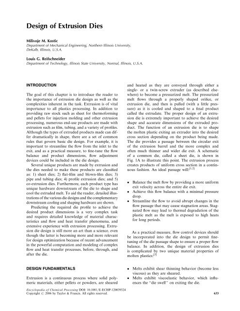
INTRODUCTION<br />
The goal <strong>of</strong> this chapter is to introduce the reader to<br />
the importance <strong>of</strong> extrusion die design as well as the<br />
complexities inherent in the task. <strong>Extrusion</strong> is <strong>of</strong> vital<br />
importance to all plastics processing. In addition to<br />
providing raw stock such as sheet for therm<strong>of</strong>orming<br />
and pellets for injection molding and other extrusion<br />
processing, numerous end-use products are made with<br />
extrusion such as film, tubing, and a variety <strong>of</strong> pr<strong>of</strong>iles.<br />
Although the types <strong>of</strong> extruded products made can differ<br />
dramatically in shape, there are a set <strong>of</strong> common<br />
rules that govern basic die design. For example, it is<br />
important to streamline the flow from the inlet to the<br />
exit, and as a practical measure, to fine-tune the flow<br />
balance and product dimensions, flow adjustment<br />
devices could be included in the die design.<br />
Several unique products are made by extrusion and<br />
the dies needed to make these products are classified<br />
as: 1) sheet dies; 2) flat-film and blown-film dies; 3)<br />
pipe and tubing dies; 4) pr<strong>of</strong>ile extrusion dies; and 5)<br />
co-extrusion dies. Furthermore, each product type has<br />
unique hardware downstream <strong>of</strong> the die to shape and<br />
cool the extruded melt. To aid the reader, detailed illustrations<br />
<strong>of</strong> the various die designs and the complementary<br />
downstream cooling and shaping hardware are shown.<br />
Predicting the required die pr<strong>of</strong>ile to achieve the<br />
desired product dimensions is a very complex task<br />
and requires detailed knowledge <strong>of</strong> material characteristics<br />
and flow and heat transfer phenomena, and<br />
extensive experience with extrusion processing. <strong>Extrusion</strong><br />
die design is still more an art than a science, even<br />
though the latter is becoming more and more relevant<br />
for design optimization because <strong>of</strong> recent advancement<br />
in the powerful computation and modeling <strong>of</strong> complex<br />
flow and heat transfer processes, before, through, and<br />
after the die.<br />
DESIGN FUNDAMENTALS<br />
<strong>Extrusion</strong> is a continuous process where solid polymeric<br />
materials, either pellets or powders, are sheared<br />
and heated as they are conveyed through either a<br />
single- or a twin-screw extruder (as described elsewhere)<br />
to become a pressurized melt. The pressurized<br />
melt flows through a properly shaped orifice, or<br />
extrusion die, and then is pulled (with a little pressure)<br />
as it is cooled and shaped to a final product<br />
called the extrudate. The proper design <strong>of</strong> an extrusion<br />
die is extremely important to achieve the desired<br />
shape and accurate dimensions <strong>of</strong> the extruded product.<br />
The function <strong>of</strong> an extrusion die is to shape<br />
the molten plastic exiting an extruder into the desired<br />
cross section depending on the product being made.<br />
The die provides a passage between the circular exit<br />
<strong>of</strong> the extrusion barrel and the more complex and<br />
<strong>of</strong>ten much thinner and wider die exit. A schematic<br />
<strong>of</strong> a common die, called a sheet die, is shown in<br />
Fig. 1A to illustrate this point. The extrusion process<br />
creates products <strong>of</strong> uniform cross section in a continuous<br />
fashion. An ideal passage will: [1,2]<br />
Balance the melt flow by providing a more uniform<br />
exit velocity across the entire die exit.<br />
Achieve this flow balance with a minimal pressure<br />
drop.<br />
Streamline the flow to avoid abrupt changes in the<br />
flow passage that may cause stagnation areas. Stagnated<br />
flow may lead to thermal degradation <strong>of</strong> the<br />
plastic melt as the melt is exposed to high heats<br />
for long periods.<br />
As a practical measure, flow control devices should<br />
be incorporated into the die design to permit finetuning<br />
<strong>of</strong> the die passage shape to ensure a proper flow<br />
balance. In addition, the design <strong>of</strong> extrusion dies<br />
is complicated by two unique material properties <strong>of</strong><br />
molten plastics: [3]<br />
Melts exhibit shear thinning behavior (become less<br />
viscous) as they are sheared.<br />
Melts exhibit viscoelastic behavior, which influences<br />
the ‘‘die swell’’ on exiting the die.<br />
Encyclopedia <strong>of</strong> Chemical Processing DOI: 10.1081/E-ECHP-120039324<br />
Copyright # 2006 by Taylor & Francis. All rights reserved. 633
634 <strong>Design</strong> <strong>of</strong> <strong>Extrusion</strong> <strong>Dies</strong><br />
Fig. 1 Coat hanger-type sheet die concept (A): (1) central inlet port; (2) manifold (distributes melt); (3) island (along with manifold,<br />
provides uniform pressure drop from inlet to die lip; (4) die lip (die exit forms a wide slit); and schematic <strong>of</strong> sheet die (B): (1)<br />
upper die plate; (2) lower die plate; (3) manifold; (4) island; (5) choker bar; (6) choker bar adjustment bolt; (7) flex die lip; (8) flex<br />
lip adjustment bolt; (9) lower lip; (10) die bolt; (11) heater cartridge.<br />
The shear thinning causes the volumetric flow to be<br />
very sensitive to slight changes in die geometry. For<br />
example, the flow for a typical polymer melt through<br />
a slit will vary with the cubic thickness <strong>of</strong> the gap.<br />
Thus, a small change in the die gap along the contour<br />
<strong>of</strong> the die exit may cause considerable change <strong>of</strong> the<br />
melt flow. The term ‘‘die swell’’ refers to the enlargement<br />
in the direction orthogonal to the flow direction.
<strong>Design</strong> <strong>of</strong> <strong>Extrusion</strong> <strong>Dies</strong> 635<br />
Swelling after exiting the die lip is due to two distinct<br />
phenomena: [4,5]<br />
Velocity relaxation (unification) <strong>of</strong> the melt flow.<br />
Viscoelastic relaxation <strong>of</strong> the strained polymer<br />
molecules.<br />
Velocity relaxation occurs because the melt is no<br />
longer under shear from the no-slip walls <strong>of</strong> the extrusion<br />
die. The melt assumes a uniform bulk velocity that<br />
causes the high-speed areas to slow down and the areas<br />
previously retarded from the wall to increase their<br />
speed. The net result is enlarging (swelling) <strong>of</strong> the melt<br />
cross-section bulk as it exits the die, while the stagnant<br />
outside region and, especially, the corners are stretched<br />
and shrunk. Newtonian and non-Newtonian fluids<br />
exhibit die swell owing to velocity relaxation. The swelling<br />
due to viscoelastic memory is a characteristic <strong>of</strong><br />
polymeric fluids and occurs because the polymer molecules<br />
are stretched in the flow direction while passing<br />
through the high-shear area before the die exit. On<br />
exiting, the molecules recoil and shorten in the flow<br />
direction. The result is an expansion in the direction<br />
orthogonal to the flow, a swelling <strong>of</strong> the diameter <strong>of</strong> a<br />
round strand on exiting the die, for example. The<br />
amount <strong>of</strong> viscoelastic swelling is a combination <strong>of</strong><br />
the material properties <strong>of</strong> the polymer as well as process<br />
conditions such as melt temperature, shear rate,<br />
and residence time under high shear, especially near<br />
the die exit. [6]<br />
The design <strong>of</strong> extrusion dies today is facilitated<br />
by computer-based simulation tools. The flow <strong>of</strong><br />
Table 1 Typical extruded product shapes<br />
Films t < 0.01 in.<br />
Sheets t > 0.01 in.<br />
Pr<strong>of</strong>iles Strand<br />
Open<br />
Hollow chamber<br />
Tubes d < 1.0 in.<br />
Pipes d > 1.0 in.<br />
non-Newtonian fluids through complex passages is<br />
routinely performed by computational fluid dynamics<br />
(CFD) programs. [7–10] Factors such as shear thinning<br />
are readily accounted in die design. The viscoelastic<br />
behavior can also be modeled today, although this<br />
simulation requires extensive material testing to obtain<br />
the required material parameters for accurate simulation<br />
results. This is discussed in more detail later in<br />
this entry.<br />
<strong>Extrusion</strong> dies vary in shape and complexity to meet<br />
the demands <strong>of</strong> the product being manufactured. There<br />
are five basic shapes <strong>of</strong> products made with extrusion<br />
dies, as illustrated in Table 1. [11,12] Film and sheet dies<br />
are called slit dies as the basic shape <strong>of</strong> the die exit is a<br />
slit. Film is also made with annular dies as in the case<br />
<strong>of</strong> blown film. Strand dies make simple geometric<br />
shapes, such as circles, squares, or triangles. Pipe and<br />
tubing dies are called annular dies as the melt exits<br />
the die in the shape <strong>of</strong> an annulus. The inner wall <strong>of</strong><br />
the annulus is supported with slight air pressure during<br />
extrusion. Open pr<strong>of</strong>ile dies make irregular geometric<br />
shapes, such as ‘‘L’’ pr<strong>of</strong>iles or ‘‘U’’ pr<strong>of</strong>iles, and combinations<br />
<strong>of</strong> these. Hollow pr<strong>of</strong>ile dies make irregular<br />
pr<strong>of</strong>iles that have at least one area that is completely<br />
surrounded by material. Examples <strong>of</strong> hollow pr<strong>of</strong>iles<br />
can be simple, such as concentric squares to make a<br />
box beam, or a very complex window pr<strong>of</strong>ile.<br />
Each extruded product relies on a die to shape the<br />
moving melt followed by shaping and cooling devices<br />
downstream to form the extrudate into the final<br />
desired shape and size. A more complete treatment <strong>of</strong><br />
these devices, which are typically water-cooled metallic
636 <strong>Design</strong> <strong>of</strong> <strong>Extrusion</strong> <strong>Dies</strong><br />
devices that contact the extrudate melt, is presented<br />
later in the section ‘‘Extrudate Cooling and Sizing<br />
Hardware.’’<br />
SHEET DIES<br />
The most common extrusion die for sheet products is<br />
the coat hanger-type manifold die as shown schematically<br />
in Fig. 1A and as a section view in Fig. 1B. The<br />
key elements <strong>of</strong> Fig. 1A are:<br />
Central inlet port: connects to the extruder barrel.<br />
Manifold: provides a streamlined channel to evenly<br />
distribute the melt to the island.<br />
Island: with the manifold serves to create an equal<br />
pressure drop from the die inlet to all points across<br />
the die exit.<br />
Die lip: wide slit across the die that provides the<br />
final sizing <strong>of</strong> the melt.<br />
Commercial sheet dies typically employ four features<br />
to control the flow to the die lip. These are the<br />
combined shape <strong>of</strong> the manifold and the island as well<br />
as the following three features shown in Fig. 1B:<br />
Choker bar: adjustable along with the width <strong>of</strong> the<br />
die and serves to tune the flow balance across the<br />
width <strong>of</strong> the die.<br />
Lower lip: sets the nominal sheet thickness.<br />
Flex-lip: adjustable along the width <strong>of</strong> the die and<br />
provides the final tuning to create uniform flow<br />
across the die.<br />
In addition, sheet dies have die bolts that hold the<br />
upper and lower die plates together. The die plates<br />
are normally heated with cartridge heaters spaced<br />
along the width <strong>of</strong> the die. This type <strong>of</strong> die is typically<br />
made for a specific type <strong>of</strong> polymer to account for the<br />
shear thinning behavior <strong>of</strong> that polymer. [11] Consequently,<br />
the flow distribution in the die will change<br />
with melt viscosity, i.e., when the power law viscosity<br />
index <strong>of</strong> the resin changes. As the polymer grades<br />
change, flow adjustments can be made at the choker<br />
bar and at the flex lip, which both span the width <strong>of</strong><br />
the die and can be adjusted at numerous points along<br />
the width. Clam shelling, or die deflection, is another<br />
cause <strong>of</strong> nonuniform flow across the die. [13,14] The<br />
higher pressures along the centerline <strong>of</strong> the die coupled<br />
with the lack <strong>of</strong> bolting to keep the die plates together<br />
cause the centerline <strong>of</strong> the die gap to widen. Clam shelling<br />
can increase as the throughput <strong>of</strong> the die increases<br />
because <strong>of</strong> higher die pressures. Thus, the flow balance<br />
across the die will be sensitive to production rates.<br />
Innovations in automatic flow adjustments have been<br />
made with designs like the Auto-Flex sheet die where<br />
the die lip gap at the flex lip is automatically adjusted<br />
by changing the length <strong>of</strong> the flex lip adjustment<br />
bolts. [15,16] The temperature-controlled bolts change<br />
length in response to cross-machine scanning <strong>of</strong> the<br />
sheet thickness.<br />
FLAT FILM AND BLOWN FILM DIES<br />
<strong>Dies</strong> used to make film less than 0.01 in. thick include<br />
flat, slit-shaped dies called T-dies and annular dies<br />
for blown film (Figs. 2 and 3). The design <strong>of</strong> the<br />
T-die is similar to the coat hanger-type die with the<br />
exception that the manifold and the land length are<br />
constant along with the width <strong>of</strong> the die. Consequently,<br />
the use <strong>of</strong> T-dies is <strong>of</strong>ten limited to coating applications<br />
with low-viscosity resins that resist thermal<br />
degradation, as the ends <strong>of</strong> the manifold in the T-die<br />
create stagnation pockets. [13] A common application<br />
for a film die is to coat a substrate like paper.<br />
Blown film dies are the most common way <strong>of</strong> making<br />
commercial films. Because the blown film is so thin,<br />
weld lines are not tolerated, and the melt is typically<br />
introduced at the bottom <strong>of</strong> a spiral mandrel through<br />
a ring-shaped distribution system, as shown in Fig. 3.<br />
A series <strong>of</strong> spiral channels, cut into the mandrel-like<br />
multiple threads, smear the melt as it flows toward<br />
the die exit. This mixing action ensures that the melt<br />
is homogenous on exiting the die. Unlike other extrusion<br />
processes, blown film is sized and quenched from<br />
melt to solid film without contacting metallic cooling<br />
elements. The interior <strong>of</strong> the melt tube is pressurized<br />
with approximately 2 in. <strong>of</strong> water pressure. This pressure<br />
causes the tube to suddenly expand into a bubble<br />
as it exits the die. The tube forms a bubble because it is<br />
pinched overhead with nip rolls, which retain the air<br />
pressure. During the process <strong>of</strong> expanding, the melt<br />
tube undergoes an order <strong>of</strong> magnitude reduction in<br />
thickness and thus cools rapidly. This quenching<br />
moment occurs at the frost line <strong>of</strong> the bubble. The melt<br />
quenching occurs with a combination <strong>of</strong> external cooling<br />
air and internal bubble cooling air, as shown in<br />
Fig. 3. After the film passes through the nip rolls, it<br />
passes through a series <strong>of</strong> guide rollers to be wound<br />
up on to a roll.<br />
PIPE AND TUBING DIES<br />
Both pipe and tubing are made in dies with an annular<br />
die exit. A pipe product is defined as being greater than<br />
1 in. in outer diameter and a tube less than 1 in. <strong>Dies</strong><br />
for these products are made in two styles: 1) in-line<br />
dies (also called spider dies) shown in Fig. 4A and
<strong>Design</strong> <strong>of</strong> <strong>Extrusion</strong> <strong>Dies</strong> 637<br />
Fig. 2 Comparing designs <strong>of</strong> T-type die (A) [(1) constant cross-section manifold; (2) constant land length] to coat hanger-type<br />
die (B) [(1) manifold cross-section decreases as distance from centerline increases; (2) land length becomes shorter farther from<br />
the centerline <strong>of</strong> the die].<br />
2) cross-head dies shown in Fig. 4B. The key elements<br />
<strong>of</strong> an in-line die are:<br />
Housing: mounts onto the end <strong>of</strong> the extruder, provides<br />
a circular passage through which the melt<br />
flows; it supports the mandrel and retaining ring.<br />
Mandrel (Torpedo): suspended in the center <strong>of</strong> the<br />
circular passage in the die body with metal bridges<br />
called spiders (typically three are used). One spider<br />
allows for passage <strong>of</strong> air into the center <strong>of</strong> the torpedo,<br />
is streamlined to avoid flow stagnation, and<br />
supports the die pin.<br />
Die pin: mates with the torpedo to provide streamlined<br />
sizing to the final inner diameter <strong>of</strong> the melt<br />
tube leaving the die; it has an air hole running<br />
through it to allow air to pass through the die body<br />
to the interior <strong>of</strong> the melt tube. A slight positive air<br />
pressure may be used to keep the inner diameter <strong>of</strong> the<br />
tubular extrudate from collapsing on exiting the die.<br />
Die land: forms the outer diameter <strong>of</strong> the tubular<br />
extrudate, held in place with a retaining ring and<br />
position adjusted with centering bolts. The die land<br />
can be changed to create a tube <strong>of</strong> a different diameter<br />
or wall thickness while keeping the original die pin.<br />
Retaining plate: secures the alignment <strong>of</strong> the die<br />
land with the die pin, bolted to the die body.<br />
Heater band: closely fitted to the housing (and for<br />
larger pipes to the exposed portion <strong>of</strong> the die pin)<br />
to ensure that the die is held at a temperature close<br />
to the required temperature <strong>of</strong> the melt.<br />
Flange for extruder attachment: tapered flange to<br />
permit alignment and attachment to extruder with<br />
split locking collars.<br />
The in-line die is the least costly for manufacture <strong>of</strong><br />
the two designs but can create defects called weld lines<br />
in the product. Weld lines occur because the melt is<br />
split and rejoined as it passes over the spider legs. A<br />
cross-head die can overcome this problem by eliminating<br />
the spiders. The melt enters the side <strong>of</strong> the die and<br />
turns 90 as it flows through a coat hanger-type passage<br />
that is wrapped around the mandrel. Key elements <strong>of</strong> a<br />
cross-head die that are different from an in-line tubing<br />
die are (see Fig. 4B):<br />
Core tube: mandrel with coat hanger-type passage<br />
that splits the flow and uniformly distributes melt<br />
along the annulus between the die pin and the die<br />
land.<br />
Side feed: melt enters from the side <strong>of</strong> the die and<br />
flows around the mandrel.<br />
Air supply: in-line with the die pin support.<br />
Another application for the cross-head-style tubing<br />
die is wire coating. The following adjustments are made<br />
to a cross-head tubing die to perform wire coating:<br />
First, instead <strong>of</strong> passing air through the core tube, a<br />
bare conductor wire is pulled through the die entering<br />
the core tube inlet and exiting the die pin.
638 <strong>Design</strong> <strong>of</strong> <strong>Extrusion</strong> <strong>Dies</strong><br />
11<br />
2<br />
12<br />
14<br />
Fig. 3 Schematic <strong>of</strong> spiral mandrel blown film die operation:<br />
(1) ring-shaped melt distribution; (2) die body; (3) spiral flow<br />
mandrel; (4) sizing ring; (5) spreader; (6) film bubble; (7) frost<br />
line; (8) solidified film; (9) bubble collapsing rollers; (10) nip<br />
rollers; (11) external bubble cooling air; (12) internal bubble<br />
cooling air inlet; (13) internal bubble cooling pipe; and<br />
(14) heated internal bubble air return.<br />
Second, the length <strong>of</strong> the die pin is shortened to<br />
cause the wire to contact the melt tube before it<br />
exits the die land.<br />
PROFILE EXTRUSION DIES<br />
Pr<strong>of</strong>ile extrusions are the most difficult to make<br />
because changes in take-up speed or screw rotational<br />
speed alone are not enough to compensate for deficient<br />
product dimensions. In the case <strong>of</strong> sheet and film, if<br />
the edges <strong>of</strong> the sheet are not at the target thickness,<br />
they can be trimmed <strong>of</strong>f and sent back to the extruder<br />
3<br />
10<br />
1<br />
9<br />
6<br />
5<br />
4<br />
7<br />
13<br />
8<br />
to be reprocessed. Pr<strong>of</strong>ile extrudates are significantly<br />
affected by nonuniform die swell unlike sheet and tube<br />
products. In the case <strong>of</strong> pr<strong>of</strong>iles with corners and other<br />
irregularities, like a square pr<strong>of</strong>ile, the die exit needed<br />
to achieve a square pr<strong>of</strong>ile is not square owing to the<br />
influence <strong>of</strong> die swell. Fig. 5 illustrates a die exit<br />
required to achieve a square extrudate. Note that the<br />
corners have an acute cusp shape and the side walls are<br />
not flat. A melt exiting this required but nonorthogonal<br />
shape will swell into a desired, orthogonal square<br />
shape. The design <strong>of</strong> nonorthogonal die exit required<br />
to achieve orthogonal pr<strong>of</strong>iles is addressed later in<br />
this entry in the section Modern <strong>Design</strong> Simulation<br />
and Computational Tools.<br />
Open pr<strong>of</strong>ile dies are typically shapes, such as ‘‘Ushaped’’<br />
or ‘‘L-shaped’’ channels, that are not axisymmetric,<br />
unlike tube shapes. Consequently, open pr<strong>of</strong>iles<br />
are more prone to cooling unevenly and thus may<br />
generate residual stresses in the solidified (frozen)<br />
extrudate that cause the product to bow. A critical<br />
design rule for open pr<strong>of</strong>iles is to maintain a uniform<br />
wall thickness throughout the product cross section.<br />
Examples <strong>of</strong> poor and better pr<strong>of</strong>ile designs are shown<br />
in Fig. 6 with the poorly designed sections shown on<br />
the left-hand side and the improved designs on the<br />
right-hand side. The difficulty with the original designs<br />
<strong>of</strong> both pr<strong>of</strong>iles A and B is the nonuniform wall thickness.<br />
The thinner sections will solidify first with the<br />
thicker sections still remaining molten in some core<br />
area. The result will be additional thermal shrinkage<br />
in the thicker regions and thus warpage <strong>of</strong> the final<br />
product. Product A will warp downward and product<br />
B will warp toward the right. These warping problems<br />
can be alleviated by making the entire cross section<br />
with more uniform thickness. Then, the entire cross<br />
section will solidify more uniformly and a little residual<br />
stress will be trapped in the solid extrudate. <strong>Design</strong> A<br />
illustrates a case where a hollow pr<strong>of</strong>ile is used to solve<br />
the warpage problem whereas design B illustrates the<br />
use <strong>of</strong> an open pr<strong>of</strong>ile to replace the thick region.<br />
The revised product designs <strong>of</strong> A and B will require<br />
more expense to fabricate the dies for these products<br />
as a set <strong>of</strong> mandrels must be made to form the hollow<br />
chambers. However, there are key benefits derived by<br />
making these changes:<br />
Better-quality products due to more uniform cooling<br />
and shrinkage: straighter products.<br />
Less material use by removing thick, unnecessary<br />
regions: savings <strong>of</strong> material costs.<br />
Faster cooling rates due to less hot plastic to cool:<br />
higher production rates.<br />
Pr<strong>of</strong>ile dies are commonly made with a series <strong>of</strong><br />
plates that are stacked together to form a complex
<strong>Design</strong> <strong>of</strong> <strong>Extrusion</strong> <strong>Dies</strong> 639<br />
Fig. 4 Schematic <strong>of</strong> in-line tubing die (A): (1) housing; (2) mandrel (torpedo); (3) die pin (interchangeable); (4) die land (interchangeable);<br />
(5) retaining plate; (6) die centering bolt; (7) air hole; (8) mandrel support (spider leg); (9) die flange (mount to extruder<br />
with split clamp); (10) heater band; and cross-head tubing (or wire coating) die (B): (1) air or wire<br />
conductor inlet; (2) melt inflow (side inlet); (3) melt exit (annulus); (4) air or wire conductor exit; (5) core tube; (6) flow splitter;<br />
(7) housing; (8) die pin; (9) die land; (10) retaining plate; (11) retaining ring bolt; (12) die centering bolt; (13) heater band.<br />
passage from the circular exit <strong>of</strong> the extruder to the<br />
required pr<strong>of</strong>ile die exit. A stacked plate design makes<br />
for easier manufacture and permits adjustments to<br />
parts <strong>of</strong> the die assembly as needed during extrusion<br />
trials to fine-tune the die flow. An example <strong>of</strong> a stack<br />
plate die that makes a U-shaped pr<strong>of</strong>ile is shown in<br />
Fig. 7. This figure illustrates an exploded view <strong>of</strong> a<br />
stack plate die, a cross-sectional view <strong>of</strong> the assembled<br />
die, and a detail <strong>of</strong> the die exit compared to the<br />
target pr<strong>of</strong>ile. Stacked plate pr<strong>of</strong>ile dies typically have<br />
these elements:<br />
Adapter plate: forms transition from circular extruder<br />
exit to approximate pr<strong>of</strong>ile shape.<br />
Transition plate: forms streamlined transition from<br />
adapter plate exit to preland plate inlet.
640 <strong>Design</strong> <strong>of</strong> <strong>Extrusion</strong> <strong>Dies</strong><br />
Preland plate: imparts significant flow adjustment<br />
by reducing thickness in high-flow areas and increasing<br />
thickness in low-flow areas anticipated downstream in<br />
the die land to make flow more uniform.<br />
Die land plate: provides a uniform cross-section<br />
passage that is typically 10 times longer than the<br />
thickness <strong>of</strong> the extrudate to relax the viscoelastic<br />
stresses in the melt before leaving the die (reduces<br />
die swell) and forms the shape <strong>of</strong> the extrudate leaving<br />
the die. The die land pr<strong>of</strong>ile has the required<br />
shape to compensate for extrudate deformation<br />
after the die (die swell and drawdown) and yield<br />
the desired shape downstream.<br />
The die exit pr<strong>of</strong>ile shown in Fig. 7 creates an<br />
extrudate that is a U-shaped pr<strong>of</strong>ile with three sides<br />
<strong>of</strong> uniform thickness and perpendicular walls to the<br />
bottom surface. The irregular shape <strong>of</strong> the die exit<br />
was generated with the aid <strong>of</strong> CFD as outlined in the<br />
section Modern <strong>Design</strong> Simulation and Computational<br />
Tools later in this entry.<br />
COEXTRUSION DIES<br />
Fig. 5 Irregular die shapes<br />
required for regular extrudates.<br />
Another important product made with extrusion dies is<br />
the creation <strong>of</strong> multilayered materials. Multilayered<br />
sheet and film materials have two applications:<br />
Making more economical material by sandwiching<br />
a less costly core material between two more expensive<br />
materials.<br />
Fig. 6 Examples <strong>of</strong> poor (on left) and improved<br />
extrusion product designs (on right) to achieve<br />
uniform product thickness: (1) pr<strong>of</strong>ile (A) made<br />
into a hollow pr<strong>of</strong>ile and (2) pr<strong>of</strong>ile (B) made into<br />
an open pr<strong>of</strong>ile.
<strong>Design</strong> <strong>of</strong> <strong>Extrusion</strong> <strong>Dies</strong> 641<br />
Fig. 7 U-Pr<strong>of</strong>ile stack die: exploded view (top); section view (lower left); and end view (lower right): (1) extruder mounting plate;<br />
(2) die adapter plate; (3) transition plate; (4) preland plate; (5) die land plate; (6) die bolt hole; (7) alignment dowel pin hole;<br />
(8) thermocouple well; (9) pressure transducer port; (10) heater band; (11) breaker plate recess. Detail (lower right): (A) die exit<br />
pr<strong>of</strong>ile and (B) product pr<strong>of</strong>ile.<br />
Creating a composite material with improved properties<br />
by combining two or more materials that each<br />
posses a desirable property.<br />
Applications <strong>of</strong> coextruded material include:<br />
Sheet stock made with an acrylic topcoat over<br />
acrylonitrile–butadiene–styrene (ABS). The acrylic<br />
provides UV resistance and gloss while the ABS<br />
provides impact resistance.<br />
Blown film with special barrier properties: one layer<br />
limits oxygen migration through the film and<br />
another provides protection from UV radiation.<br />
There are two common methods <strong>of</strong> achieving<br />
co-extruded materials: feed block manifolds and<br />
multimanifolds within dies. [17] Two, three, or more<br />
melt streams may be combined with co-extrusion dies.<br />
The key elements <strong>of</strong> a feed block manifold as shown in<br />
Fig. 8A are:<br />
Inlet ports for the upper layer, middle layer, and<br />
lower layer.<br />
Streamlined melt lamination area that channels<br />
separate flow streams into one laminated melt<br />
stream inside feed block.<br />
Adapter plate between the feed block and the sheet<br />
die.<br />
Sheet die, which is identical to a monolayer die. The<br />
laminated melt stream enters the center <strong>of</strong> the die<br />
and spreads out along the manifold flowing out <strong>of</strong><br />
the die exit as a distinct multilayer extrudate.
642 <strong>Design</strong> <strong>of</strong> <strong>Extrusion</strong> <strong>Dies</strong><br />
Fig. 8 Coextrusion feed block manifold and sheet die (A): (1) sheet die with flow restriction; (2) adapter plate; (3) feed block<br />
asembly; (4) core material layer inlet; (5) upper material layer inlet; (6) lower material layer inlet; and coextrusion multimanifold<br />
sheet die (B): (1) lower melt channel; (2) upper melt channel; (3) lower choker bar; (4) lower choker bar adjustment bolt; (5) upper<br />
choker bar; (6) upper choker bar adjustment bolt; (7) flex lip.<br />
An alternative to the feed block design is a multimanifold<br />
die as depicted in Fig. 8B. The key elements<br />
<strong>of</strong> this design are:<br />
It is similar to a monolayer extrusion die, except<br />
that there is more than one feed channel.<br />
Each melt channel has its own choker bar for flow<br />
control.<br />
Melt streams converge inside the die near the die<br />
exit and emerge as a distinct multilayer extrudate.<br />
The feed block technique is cheaper to implement<br />
than the multimanifold approach, but because the melt<br />
streams travel some distance before reaching the die<br />
exit, irregular flow patterns can develop at the interface<br />
<strong>of</strong> the different melt streams. [18–20] This is especially
<strong>Design</strong> <strong>of</strong> <strong>Extrusion</strong> <strong>Dies</strong> 643<br />
true when attempting to coextrude melts <strong>of</strong> significantly<br />
differing viscosities. Lower-viscosity melt tends<br />
to encapsulate the more viscous melt. The alternative<br />
method is to keep the melt streams separated until just<br />
before the die exit as is done with the multimanifold<br />
design. Multimanifold designs permit coextrusion <strong>of</strong><br />
plastic melts having significantly differing viscosities.<br />
With any coextrusion process, however, there must<br />
exist basic chemical compatibility between the neighboring<br />
melt streams to ensure good cohesion between<br />
the layers.<br />
EXTRUDATE COOLING AND SIZING<br />
HARDWARE<br />
With the exception <strong>of</strong> blown film and strand pr<strong>of</strong>iles,<br />
all extrudates require cooling and=or sizing by some<br />
metallic element. Table 2 summarizes the type <strong>of</strong> cooling<br />
and sizing hardware used for the various extrusion<br />
products. [21] In the case <strong>of</strong> sheet extrusion, the cooling<br />
is achieved with a chill roll stack, schematically illustrated<br />
in Fig. 9. The chill rolls are typically highly<br />
polished chrome-plated rollers that impart the surface<br />
gloss on sheet products and cool the extrudate while<br />
pulling the melt away from the die with a constant<br />
take-up speed. The average sheet thickness is achieved<br />
by the combination <strong>of</strong> extrusion screw rotational<br />
speeds and take-up speed adjustments. If the line speed<br />
taking the extrudate melt away from the die is greater<br />
than the average die exit speed, the thickness <strong>of</strong> the<br />
sheet decreases. This is called drawdown.<br />
In the case <strong>of</strong> pipe and tubing products, the nominal<br />
outer and inner diameters <strong>of</strong> the extrudate are made by<br />
selecting the appropriate size <strong>of</strong> the die pin and die<br />
land. The final outer dimension <strong>of</strong> tubing products is<br />
achieved with sizing rings that are typically placed in<br />
the vacuum water bath, shown schematically in<br />
Fig. 10. The outer diameter <strong>of</strong> the tube is set with the<br />
sizing ring as the vacuum, which combined with a<br />
slight positive pressure inside the tube, forces the<br />
Table 2<br />
products<br />
Cooling and sizing devices for various extruded<br />
Product type Cooling and sizing device<br />
Film and sheet Chill roll<br />
Blown film External and internal<br />
bubble air<br />
Pr<strong>of</strong>iles—strand Water tank<br />
Pr<strong>of</strong>iles—open and<br />
hollow chamber<br />
Vacuum calibrators<br />
and water tank<br />
Tubing and pipes Sizing rings and<br />
vacuum water tank<br />
extrudate against the inner race <strong>of</strong> the ring. The desired<br />
inner diameter <strong>of</strong> the tube is achieved by adjusting the<br />
take-up speed <strong>of</strong> the extrudate relative to the average<br />
die exit speed. If the take-up speed is greater than the<br />
average die exit speed, the cross-sectional area<br />
decreases. Because the outer diameter <strong>of</strong> the tube is<br />
set with a sizing ring, the inner diameter will increase.<br />
Thus, the wall thickness <strong>of</strong> a tube is controlled this way.<br />
The sizing and cooling <strong>of</strong> pr<strong>of</strong>iles have special<br />
requirements because <strong>of</strong> their complex shape. [21,22]<br />
These devices are called calibrators and are <strong>of</strong>ten as<br />
complicated as the die. To maintain the shape <strong>of</strong> a pr<strong>of</strong>ile,<br />
vacuum is applied while simultaneously cooling<br />
the extrudate. Some calibrators, called wet vacuum<br />
calibrators, alternately inject water between the extrudate<br />
and the calibrator to lubricate and augment the<br />
cooling. A schematic <strong>of</strong> the dry vacuum calibrator setup<br />
used to size and cool the U-shaped pr<strong>of</strong>ile is shown in<br />
Fig. 11. Fig. 11B illustrates a partially disassembled<br />
vacuum calibrator to reveal the following details: the<br />
vacuum channels and the cooling lines that simultaneously<br />
hold the moving extrudate in the desired shape<br />
while cooling it. Vacuum calibrators for pr<strong>of</strong>iles are<br />
typically made <strong>of</strong> stainless steel to withstand the abrasive<br />
action <strong>of</strong> extrudates while in contact with the calibrator<br />
during the cooling process. For example, the<br />
U-pr<strong>of</strong>ile shown in Fig. 11 will tend to shrink onto the<br />
core feature <strong>of</strong> the lower calibrator and pull away from<br />
the upper calibrator surfaces. This complicates the<br />
design <strong>of</strong> the calibrator as the extrudate will conform<br />
to the ideal calibrator shape as it deforms. The cooling<br />
<strong>of</strong> the extrudate also complicates the simulation and<br />
design <strong>of</strong> the calibrator as discussed in the next section.<br />
MODERN DESIGN SIMULATION AND<br />
COMPUTATIONAL TOOLS<br />
The development <strong>of</strong> powerful computing hardware<br />
and pr<strong>of</strong>icient numerical techniques makes it possible<br />
now to simulate, analyze, and optimize three-dimensional<br />
extrusion processes with complex geometries,<br />
including nonlinear and viscoelastic polymer behavior.<br />
Numerical simulation has the potential to uncover<br />
important interior details <strong>of</strong> the extrusion process, such<br />
as velocity, shear stress, pressure, and temperature fields<br />
in the region <strong>of</strong> interest, which is not possible to do<br />
experimentally. A critical challenge for simulation methods<br />
is the ability to accurately represent the complex viscoelastic<br />
polymer material behavior that is dependent on<br />
process parameters, like shearing flow rate and temperature.<br />
Another challenge is to accurately model the complex<br />
geometry and the boundary conditions <strong>of</strong> extrusion<br />
dies and calibrators, especially for pr<strong>of</strong>ile extrusions.<br />
Experts in the polymer processing field have cited that<br />
the increasing complexity <strong>of</strong> product designs, coupled
644 <strong>Design</strong> <strong>of</strong> <strong>Extrusion</strong> <strong>Dies</strong><br />
Fig. 9 Chill roll stack for sheet extrusion: (1) sheet die with flow restrictor; (2) molten sheet extrudate; (3) lower chill roll (all chill<br />
rolls temperature controlled); (4) middle chill roll (imparts gloss=surface texture to sheet); (5) upper chill roll; and (6) solidified sheet.<br />
with the shorter development times, and a shortage <strong>of</strong><br />
qualified engineers fuel the need for more process simulation<br />
in industry. [23] As already stated, several commercial<br />
polymer flow simulation programs are used for<br />
pr<strong>of</strong>ile die design. [7–10] However, because the cooling rate<br />
<strong>of</strong> the extruded product determines the speed <strong>of</strong> the<br />
extrusion line, optimal design <strong>of</strong> a calibrator is also<br />
critical to productive operations. In addition, the design<br />
<strong>of</strong> the calibrator has an influence on the straightness <strong>of</strong><br />
the final product because <strong>of</strong> uneven cooling results<br />
in unfavorable thermal deformations and warped<br />
products. [24]<br />
Analytical solutions have been developed to aid the<br />
design <strong>of</strong> calibrators for simple shapes, such as sheets<br />
and pipes. [22] More complex shapes, such as window<br />
pr<strong>of</strong>iles, require the use <strong>of</strong> numerical finite element<br />
methods that can model arbitrary shapes. [25]<br />
Computational Fluid Dynamics Simulation<br />
<strong>of</strong> Polymer Flow for Die <strong>Design</strong><br />
The design process begins with a target product<br />
shape. The objective <strong>of</strong> the simulation is to determine
<strong>Design</strong> <strong>of</strong> <strong>Extrusion</strong> <strong>Dies</strong> 645<br />
Fig. 10 Tubing vacuum water-bath calibration and take-<strong>of</strong>f: (1) tubing=pipe die; (2) molten tube extrudate; (3) baffle; (4)<br />
vacuum water tank; (5) sizing ring; (6) solidified tube; and (7) puller.<br />
the required die passage that results in a balanced<br />
mass flow exiting the die and an extrudate shape<br />
downstream <strong>of</strong> the die that matches the target pr<strong>of</strong>ile.<br />
A commercial polymer flow simulation program<br />
was used to simulate the three-dimensional die flow<br />
and heat transfer through the U-pr<strong>of</strong>ile die, shown in<br />
Fig. 12. [7,26] Because the last two die plates have the<br />
greatest influence on the extrudate pr<strong>of</strong>ile shape, only<br />
these two plates are designed with flow simulation.<br />
Simulation requires the following inputs: [7]<br />
1. Geometric model <strong>of</strong> the die passage<br />
a. Two-dimensional pr<strong>of</strong>ile <strong>of</strong> the inlet plane<br />
<strong>of</strong> the passage<br />
b. Two-dimensional pr<strong>of</strong>ile <strong>of</strong> the target extrudate<br />
shape.<br />
Fig. 11 Pr<strong>of</strong>ile vacuum calibration and take-<strong>of</strong>f. (A) Section view <strong>of</strong> calibration process: (1) melt enters pr<strong>of</strong>ile die; (2) pr<strong>of</strong>ile die<br />
stack; (3) molten pr<strong>of</strong>ile extrudate; (4) calibrator (cools, shapes, and sizes extrudate); (5) solidified plastic; (6) puller; (7) orientation <strong>of</strong><br />
pr<strong>of</strong>ile. (B) Partially disassembled calibrator: (8) pr<strong>of</strong>ile passing through calibrator; (9) upper calibrator stack; (10) lower calibrator<br />
stack; (11) upper vacuum channel; (12) lower vacuum channel; (13) core feature <strong>of</strong> lower calibrator; (14) cooling line.
646 <strong>Design</strong> <strong>of</strong> <strong>Extrusion</strong> <strong>Dies</strong><br />
c. Specification <strong>of</strong> the preland length, the die<br />
land length (note that die land has a constant<br />
cross-sectional pr<strong>of</strong>ile), and the free<br />
surface flow length after the die exit.<br />
2. Thermomechanical properties <strong>of</strong> the polymer<br />
melt: density, heat capacity, and thermal<br />
conductivity.<br />
3. Rheological properties <strong>of</strong> the polymer melt:<br />
non-Newtonian viscosity as a function <strong>of</strong> shear<br />
rate and temperature and=or viscoelastic material<br />
characteristics.<br />
4. Process conditions: inlet melt temperature, mass<br />
flow rate into the die passage (or pressure at the<br />
inlet), die wall temperature, and take-up speed<br />
<strong>of</strong> the extrudate downstream from the die.<br />
The computational domain resembles the real<br />
three-dimensional die geometry and a free surface<br />
flow after the die, where velocity redistribution<br />
(equalization) and stress relaxation take place in a<br />
short distance downstream from the die exit (Fig. 13A).<br />
Because <strong>of</strong> the symmetry <strong>of</strong> the die design, only half<br />
<strong>of</strong> the die passage is modeled (Fig. 13B). A finite element<br />
model <strong>of</strong> the die passage and the free surface<br />
region consists <strong>of</strong> 16,592 hexahedral elements and<br />
19,530 nodes, as detailed elsewhere. [26] The computational<br />
domain must have appropriate boundary conditions<br />
to represent the realistic conditions present<br />
as the melt passes through the die and exits into a<br />
free surface flow (Fig. 13C). The used commercial<br />
CFD program implements an ‘‘inverse extrusion’’<br />
solution algorithm, which computes the shape <strong>of</strong> the<br />
die exit (die land pr<strong>of</strong>ile) required to achieve the target<br />
pr<strong>of</strong>ile dimensions at the exit <strong>of</strong> the free surface<br />
domain. [7] The program solves for the shape <strong>of</strong> the<br />
Fig. 12 U-Pr<strong>of</strong>ile die plates designed with<br />
CFD simulation.<br />
die land that will achieve the target pr<strong>of</strong>ile after die<br />
swell occurs. [7,26]<br />
Cooling Simulation and Calibrator <strong>Design</strong><br />
For optimal design <strong>of</strong> the pr<strong>of</strong>ile extrusion calibrators,<br />
cooling bath, and other cooling accessories, a comprehensive<br />
knowledge about the extrudate heat transfer<br />
process (cooling) is necessary. The biggest challenge<br />
in modeling <strong>of</strong> pr<strong>of</strong>ile extrudate cooling is to specify<br />
properly the boundary conditions in every local part<br />
<strong>of</strong> the cooling equipment. It is possible to approximate<br />
heat transfer coefficients or determine the values<br />
experimentally. [27,28] It may be very difficult to estimate<br />
the heat transfer coefficient in a vacuum calibrator<br />
because it is not possible to predict, without experimental<br />
verification, where the polymer has a good<br />
contact with the cooling wall and what is the influence<br />
<strong>of</strong> a thin layer <strong>of</strong> cooling water being sucked in from<br />
the cooling bath. However, even estimated values can<br />
be used to get a good overall picture <strong>of</strong> the process,<br />
as the polymer materials have a fairly low thermal conductivity.<br />
This means that the obtained results are not<br />
exact, but they can be very useful for design. Therefore,<br />
the modeling and simulation <strong>of</strong> extrudate cooling is a<br />
useful tool for studying the pr<strong>of</strong>ile extrusion cooling<br />
process, as well as for design improvement <strong>of</strong> the<br />
calibrators and other cooling equipment. Other<br />
researchers also indicated that calibration design can<br />
be done to estimate the cooling performance. [29,30] An<br />
illustration <strong>of</strong> the type <strong>of</strong> information that can be<br />
obtained by simulating the cooling <strong>of</strong> the extrudate<br />
is shown by cooling simulation <strong>of</strong> a U-pr<strong>of</strong>ile extrudate<br />
using a commercial simulation program and
<strong>Design</strong> <strong>of</strong> <strong>Extrusion</strong> <strong>Dies</strong> 647<br />
Fig. 13 Computational model for U-Pr<strong>of</strong>ile die design: (A) preland, die land, and free surface as computational domain; (B)<br />
finite element mesh (symmetry exploited to reduce computational requirements); (C) boundary conditions for simulation <strong>of</strong> polymer<br />
flow through die and extrudate free surface; and (D) relevant pr<strong>of</strong>iles: (1) preland inlet; (2) die land (uniform along flow<br />
length); (3) final free surface (target extrudate pr<strong>of</strong>ile); and (4) symmetry plane.<br />
experimentally determined heat transfer coefficients in<br />
a vacuum calibrator. [26]<br />
CONCLUSIONS AND DESIGN<br />
RECOMMENDATIONS<br />
As stated above, extrusion die design is a complex<br />
task because the extrudate product dimensions depend<br />
not only on the die design (die shape), but also on the<br />
polymer properties and extrusion process parameters.<br />
The following are general recommendations for extrusion<br />
die design:<br />
Achieve a balanced melt flow exiting the die.<br />
Minimize the pressure drop required to achieve a<br />
balanced flow to permit the maximum mass flow<br />
rate with the smallest-sized extruder required.<br />
Provide flow control devices in the die to optimize<br />
the flow distribution.<br />
Streamline the die flow passage to avoid flow stagnation<br />
areas. Such areas facilitate degradation <strong>of</strong><br />
the polymer melt due to prolonged exposure at<br />
elevated temperatures.<br />
Use modular design with stacked plates for manufacturability,<br />
convenient assembly, and disassembly,<br />
as well as convenient modifications and cleaning.<br />
Die land length should be at least 10 times the product<br />
thickness (or gap) to facilitate the polymer<br />
melt stress relaxation within the die.
648 <strong>Design</strong> <strong>of</strong> <strong>Extrusion</strong> <strong>Dies</strong><br />
Avoid thick and nonuniform extrudate wall thickness<br />
to achieve better flow balance control in the<br />
die, minimize material use, reduce cooling times,<br />
and minimize postextrusion warping <strong>of</strong> the product.<br />
Avoid or minimize hollow pr<strong>of</strong>iles as they increase<br />
die fabrication costs and complicate the cooling<br />
process <strong>of</strong> the extrudate.<br />
Except for circular dies, it is virtually impossible to<br />
design a die geometry to achieve a quality extrudate<br />
product for a wide range <strong>of</strong> polymers and extrusion<br />
process conditions. That is why a good die design must<br />
incorporate appropriate adjustment features to be set<br />
(or tuned) during the extrusion process to compensate<br />
for the deficiency <strong>of</strong> the final product, i.e., the cooled<br />
extrudate. For a fixed die geometry, adjustment <strong>of</strong><br />
the deficient pr<strong>of</strong>ile may be achieved by changing<br />
extrusion process parameters, like temperature, flow<br />
rate, cooling rate, and=or take-up speed. However, it<br />
is important to optimize the die design to make the<br />
necessary adjustments practically possible. This is<br />
why polymer extrusion die design has most <strong>of</strong>ten relied<br />
on experience, empirical data, and expensive trial and<br />
error adjustments to design and optimize a die and<br />
complementary process parameters. However, by integrating<br />
computational simulation with empirical data<br />
and by improving the extrusion monitoring instrumentation<br />
the die design process can be improved. A better<br />
die design method yields improved product quality and<br />
a reduction in the time to design and optimize the<br />
extrusion process, resulting in lower costs. It is important<br />
to state again that computational simulation and<br />
empirical extrusion engineering are synergistic in<br />
nature. They have their exclusive strengths and<br />
weaknesses that cannot replace each other, but, if<br />
properly integrated, may significantly improve extrusion<br />
die design.<br />
REFERENCES<br />
1. Tadmor, Z.; Gogos, C.G. Die forming. In Principles<br />
<strong>of</strong> Polymer Processing; John Wiley & Sons,<br />
1979; 521–524.<br />
2. Rosato, D.V. Die design and performance. In<br />
Extruding Plastics; Chapman & Hall, 1998;<br />
228–282.<br />
3. Rauwendaal, C. Die forming. In Understanding<br />
<strong>Extrusion</strong>; Hanser, 1998; 107–109.<br />
4. Tadmor, Z.; Gogos, C.G. Polymer melt rheology.<br />
In Principles <strong>of</strong> Polymer Processing; John Wiley<br />
& Sons, 1979; 148–172.<br />
5. Michaeli, W. Monoextrusion dies for thermoplastics.<br />
In <strong>Extrusion</strong> <strong>Dies</strong> for Plastics and Rubber,<br />
2nd Ed.; Hanser, 1992; 195–198.<br />
6. Woei-Shyong, L.; Hsueh-Yu, H. Experimental<br />
study on extrudate swell and die geometry <strong>of</strong><br />
pr<strong>of</strong>ile extrusion. J. Polym. Eng. Sci. 2000, 40 (5),<br />
1085–1094.<br />
7. Polyflow (application s<strong>of</strong>tware); Fluent Inc.:<br />
Lebanon, NH; http:==www.fluent.com=s<strong>of</strong>tware=<br />
polyflow (accessed Mar 2005).<br />
8. Flow 2000; Compuplast International: Zlin,<br />
Czech Republic; http:==www.compuplast.com=<br />
FLOW_2000.htm (accessed Mar 2005).<br />
9. Dieflow: Chippewa Falls WI; http:==www.<br />
dieflow.com (accesses Mar 2005).<br />
10. HyperXtrude, Altair Engineering, Inc.: Troy, MI;<br />
http:==www.altair.com=s<strong>of</strong>tware=hw_hx.htm<br />
(accessed Mar 2005).<br />
11. Michaeli, W. Monoextrusion dies for thermoplastics.<br />
In <strong>Extrusion</strong> <strong>Dies</strong> for Plastics and Rubber,<br />
2nd Ed.; Hanser, 1992; 128–194.<br />
12. Levy, S.; Carley, J.F. <strong>Extrusion</strong> dies for specific<br />
product lines. In Plastics <strong>Extrusion</strong> Technology<br />
Handbook, 2nd Ed.; Industrial Press, Inc., 1989;<br />
96–139.<br />
13. <strong>Extrusion</strong> <strong>Dies</strong> Industries, LLC: Chippewa Falls,<br />
WI; http:==www.extrusiondies.com (accessed<br />
Mar 2005).<br />
14. Michaeli, W. Monoextrusion dies for thermoplastics.<br />
In <strong>Extrusion</strong> <strong>Dies</strong> for Plastics and Rubber,<br />
2nd Ed.; Hanser, 1992; 147–148.<br />
15. Levy, S.; Carley, J.F. On-line and computer control<br />
<strong>of</strong> the extrusion process. In Plastics <strong>Extrusion</strong><br />
Technology Handbook, 2nd Ed.; Industrial Press,<br />
Inc., 1989; 302–304.<br />
16. Tadmor, Z.; Gogos, C.G. Die forming. In Principles<br />
<strong>of</strong> Polymer Processing; John Wiley & Sons,<br />
1979; 533–537.<br />
17. Michaeli, W. Coextrusion dies for thermoplastics.<br />
In <strong>Extrusion</strong> <strong>Dies</strong> for Plastics and Rubber, 2nd<br />
Ed.; Hanser, 1992; 234–238.<br />
18. Levy, S.; Carley, J.F. <strong>Extrusion</strong> dies for specific<br />
product lines. In Plastics <strong>Extrusion</strong> Technology<br />
Handbook, 2nd Ed.; Industrial Press, Inc., 1989;<br />
228–233.<br />
19. Gifford, W.A. A three-dimensional analysis <strong>of</strong><br />
coextrusion in a single manifold flat die. J. Polym.<br />
Eng. Sci. 2000, 40 (9), 2095–2100.<br />
20. Michaeli, W. Coextrusion dies for thermoplastics.<br />
In <strong>Extrusion</strong> <strong>Dies</strong> for Plastics and Rubber, 2nd<br />
Ed.; Hanser, 1992; 215–221.<br />
21. Levy, S.; Carley, J.F. <strong>Extrusion</strong> dies for specific<br />
product lines. In Plastics <strong>Extrusion</strong> Technology<br />
Handbook, 2nd Ed.; Industrial Press, Inc., 1989;<br />
188–213.<br />
22. Michaeli, W. Calibration <strong>of</strong> pipes and pr<strong>of</strong>iles. In<br />
<strong>Extrusion</strong> <strong>Dies</strong> for Plastics and Rubber, 2nd Ed.;<br />
Hanser, 1992; 311–326.
<strong>Design</strong> <strong>of</strong> <strong>Extrusion</strong> <strong>Dies</strong> 649<br />
23. Michaeli, W.; Pfannschmidt, O.; Franz, A.; Vogt,<br />
N. Pre-computing developments—progress report<br />
on process simulation in industry. Kunstst<strong>of</strong>fe<br />
2001, 91 (7), 32–39.<br />
24. Brown, R.J. Predicting How the Cooling and<br />
Resulting Shrinkage <strong>of</strong> Plastics Affect the Shape<br />
and Straightness <strong>of</strong> Extruded Products. Proceedings<br />
<strong>of</strong> the Annual Technical Conference <strong>of</strong> the<br />
Society <strong>of</strong> Plastics Engineers, May 4–8, 2000.<br />
25. Sheehy, P.; Tanguy, P.A.; Blouin, D. A finite<br />
element model for complex pr<strong>of</strong>ile calibration.<br />
J. Polym. Eng. Sci. 1994, 34 (8), 650–656.<br />
26. Reifschneider, L.G.; <strong>Kostic</strong>, M.K.; Vaddiraju,<br />
S.R. Computational <strong>Design</strong> <strong>of</strong> a U-Pr<strong>of</strong>ile Die<br />
and Calibrator. Proceedings <strong>of</strong> the Annual<br />
Technical Conference <strong>of</strong> the Society <strong>of</strong> Plastics<br />
Engineers, Chicago, May 16–20, 2004.<br />
27. Michaeli, W. Calibration <strong>of</strong> pipes and pr<strong>of</strong>iles. In<br />
<strong>Extrusion</strong> <strong>Dies</strong> for Plastics and Rubber, 2nd Ed.;<br />
Hanser, 1992; 324–329.<br />
28. Fredette, L.; Tanguy, P.A.; Hurez, P.; Blouin, D.<br />
On the determination <strong>of</strong> heat transfer coefficient<br />
between PVC and steel in vacuum extrusion<br />
calibrators. Int. J. Num. Methods Heat Fluid<br />
Flow 1996, 6, 3–12.<br />
29. Placek, L.; Svabik, J.; Vlcek, J. Cooling <strong>of</strong><br />
Extruded Plastic Pr<strong>of</strong>iles. Proceedings <strong>of</strong> the<br />
Annual Technical Conference <strong>of</strong> the Society <strong>of</strong><br />
Plastics Engineers, May 4–8, 2000.<br />
30. Carneiro, O.S.; Nobrega, J.M.; Covas, J.A.;<br />
Oliveria, P.J.; Pinho, F.T. A Study <strong>of</strong> the Thermal<br />
Performance <strong>of</strong> Calibrators. Proceedings <strong>of</strong> the<br />
Annual Technical Conference <strong>of</strong> the Society <strong>of</strong><br />
Plastics Engineers, Chicago, May 16–20, 2004.