SRI986 Electro-Pneumatic Positioner - webadmin1.net
SRI986 Electro-Pneumatic Positioner - webadmin1.net
SRI986 Electro-Pneumatic Positioner - webadmin1.net
- No tags were found...

You also want an ePaper? Increase the reach of your titles
YUMPU automatically turns print PDFs into web optimized ePapers that Google loves.
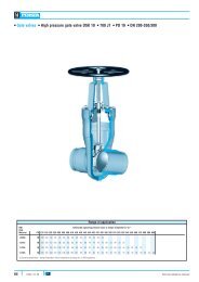
14 <strong>SRI986</strong> MI EVE0102 A-(en)3 ELECTRICAL CONNECTIONSDuring installation, the installation requirements by DINVDE 0100 and/or DIN VDE 0800, as well as locallyapplicable requirements must be observed.In addition, the requirements of VDE 0165 must beobserved for systems associated with hazardousareas.Further important instructions are contained in page 22(safety requirements, explosion protection).If an earth connection or potential equalization arerequired, the appropriate connections must be set upfor an internal earth connection 36 or an external earthconnection 37 .The units must be operated in a stationary position.The line (cable) is guided through a screwed gland 7Pg 13.5 . This is suitable for line diameters of 6 to 12mm.The electrical connections for the command variable wis made at the + and – screw terminals 38 , which aresuitable for wire cross-sections of up to 2.5 mm² (seeFig. 21).Check polarity !38 36 384 START-UPBefore commissioning electro-pneumatic positionersmust be matched to the stroke and rotation angle ofthe actuator and to the input signal range.The instruments can be connected to the 0 to 20 mAinput signals, 4 to 20 mA input signals or split rangeswithout altering the basic adjustments.The supply air connected should be min. 1.4 bar andmax. 6 bar, but should not exceed the maximum operatingpressure of the diaphragm actuator.4.1 Setting the gainThe gain and thus the sensitivity of the positioner areset by means of the throttling screw 44 (see page 31).The throttling screw is screwed in all the way in thefactory, i.e. it is set to maximum gain. This gain varieswith the supply air pressure, as shown in the followingtable:Supply airSingle-actingpositionermax. gainDouble-actingpositioner1.4 bar approx. 150 approx. 1004 bar approx. 90 approx. 1506 bar approx. 60 approx. 180Fig. 21: Electrical connections7 37The linear gain is indicated. These values are basedon the built-in range spring FES 628/1.From this basic setting the gain can be matched to thedynamic requirements of the control system(counter-clockwise rotation of the throttling screw 44results in less gain).Note :The zero point must be adjusted following eachchange of gain.In order to ensure reliable pressure reduction in theactuator, the throttling screw 44 should not be openedbeyond ¼ turn at 6 bar. A limiting screw 45 istherefore incorporated.The basic setting at the factory permits a maximumopening of the throttling screw 44 of approx. 1 turn.