design of adaptive noise canceller using lms algorithm - ijater
design of adaptive noise canceller using lms algorithm - ijater
design of adaptive noise canceller using lms algorithm - ijater
- No tags were found...

You also want an ePaper? Increase the reach of your titles
YUMPU automatically turns print PDFs into web optimized ePapers that Google loves.
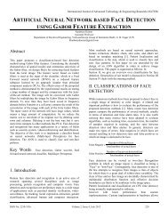
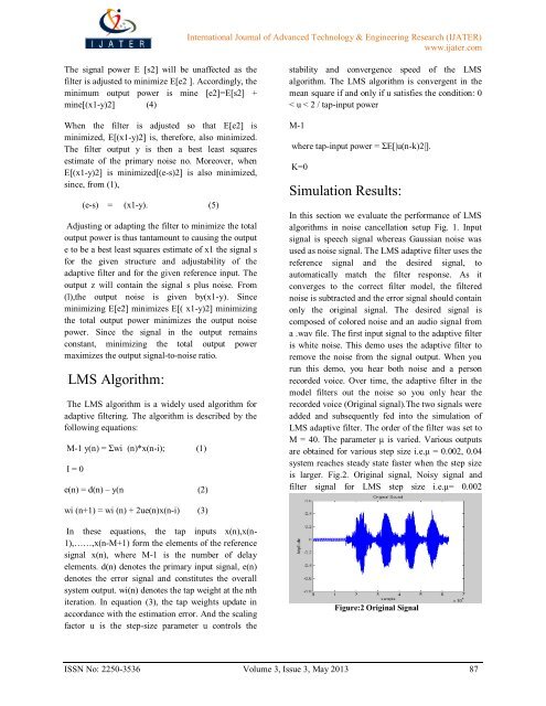
International Journal <strong>of</strong> Advanced Technology & Engineering Research (IJATER)www.<strong>ijater</strong>.comThe signal power E [s2] will be unaffected as thefilter is adjusted to minimize E[e2 ]. Accordingly, theminimum output power is mine [e2]=E[s2] +mine[(x1-y)2] (4)When the filter is adjusted so that E[e2] isminimized, E[(x1-y)2] is, therefore, also minimized.The filter output y is then a best least squaresestimate <strong>of</strong> the primary <strong>noise</strong> no. Moreover, whenE[(x1-y)2] is minimized[(e-s)2] is also minimized,since, from (1),(e-s) = (x1-y). (5)Adjusting or adapting the filter to minimize the totaloutput power is thus tantamount to ca<strong>using</strong> the outpute to be a best least squares estimate <strong>of</strong> x1 the signal sfor the given structure and adjustability <strong>of</strong> the<strong>adaptive</strong> filter and for the given reference input. Theoutput z will contain the signal s plus <strong>noise</strong>. From(l),the output <strong>noise</strong> is given by(x1-y). Sinceminimizing E[e2] minimizes E[( x1-y)2] minimizingthe total output power minimizes the output <strong>noise</strong>power. Since the signal in the output remainsconstant, minimizing the total output powermaximizes the output signal-to-<strong>noise</strong> ratio.LMS Algorithm:The LMS <strong>algorithm</strong> is a widely used <strong>algorithm</strong> for<strong>adaptive</strong> filtering. The <strong>algorithm</strong> is described by thefollowing equations:M-1 y(n) = Σwi (n)*x(n-i); (1)I = 0e(n) = d(n) – y(n (2)stability and convergence speed <strong>of</strong> the LMS<strong>algorithm</strong>. The LMS <strong>algorithm</strong> is convergent in themean square if and only if u satisfies the condition: 0< u < 2 / tap-input powerM-1where tap-input power = ΣE[|u(n-k)2|].K=0Simulation Results:In this section we evaluate the performance <strong>of</strong> LMS<strong>algorithm</strong>s in <strong>noise</strong> cancellation setup Fig. 1. Inputsignal is speech signal whereas Gaussian <strong>noise</strong> wasused as <strong>noise</strong> signal. The LMS <strong>adaptive</strong> filter uses thereference signal and the desired signal, toautomatically match the filter response. As itconverges to the correct filter model, the filtered<strong>noise</strong> is subtracted and the error signal should containonly the original signal. The desired signal iscomposed <strong>of</strong> colored <strong>noise</strong> and an audio signal froma .wav file. The first input signal to the <strong>adaptive</strong> filteris white <strong>noise</strong>. This demo uses the <strong>adaptive</strong> filter toremove the <strong>noise</strong> from the signal output. When yourun this demo, you hear both <strong>noise</strong> and a personrecorded voice. Over time, the <strong>adaptive</strong> filter in themodel filters out the <strong>noise</strong> so you only hear therecorded voice (Original signal).The two signals wereadded and subsequently fed into the simulation <strong>of</strong>LMS <strong>adaptive</strong> filter. The order <strong>of</strong> the filter was set toM = 40. The parameter μ is varied. Various outputsare obtained for various step size i.e.μ = 0.002, 0.04system reaches steady state faster when the step sizeis larger. Fig.2. Original signal, Noisy signal andfilter signal for LMS step size i.e.μ= 0.002wi (n+1) = wi (n) + 2ue(n)x(n-i) (3)In these equations, the tap inputs x(n),x(n-1),……,x(n-M+1) form the elements <strong>of</strong> the referencesignal x(n), where M-1 is the number <strong>of</strong> delayelements. d(n) denotes the primary input signal, e(n)denotes the error signal and constitutes the overallsystem output. wi(n) denotes the tap weight at the nthiteration. In equation (3), the tap weights update inaccordance with the estimation error. And the scalingfactor u is the step-size parameter u controls theFigure:2 Original SignalISSN No: 2250-3536 Volume 3, Issue 3, May 2013 87