IG4300 Owner's Manual NTP Edit 2 - Kipor Power Systems
IG4300 Owner's Manual NTP Edit 2 - Kipor Power Systems
IG4300 Owner's Manual NTP Edit 2 - Kipor Power Systems
- No tags were found...

Create successful ePaper yourself
Turn your PDF publications into a flip-book with our unique Google optimized e-Paper software.
SINEMASTERDIGITAL GENERATOR<strong>IG4300</strong>OWNER’S MANUAL
This page intentionally blank
Thank you for purchasing a <strong>Kipor</strong> Generator.PREFACEThis manual covers the operation and preventive maintenance of the <strong>IG4300</strong> generator with EPA andCalifornia Air Resources Board (CARB) certification if so designated.All information in this publication is based on the latest product information available at the time ofprinting.We reserve the right to make changes at any time without notice and without incurring any obligation.No part of this publication may be reproduced without written permission.This manual should be considered a permanent part of the generator and should remain with it if it isresold.Pay special attention to statements preceded by the following words:Failure to properly follow these precautions can result in property damage,serious injury or DEATH!Read all labels and the owner's manual before operating this generator.Generators produce carbon monoxide, a poisonous, colorless, odorless gas that can cause death orserious injury.Indoor use of a generator can kill quickly. Generators should be used outdoors only.Generators should be used outdoors only and away from garages and open windows and protectedfrom rain and snow.Always stop engine before refueling. Wait 5 minutes before restarting.Keep any source of ignition away from the fuel tank at all times.
CONTENTS1. SAFETY INSTRUCTIONS ··································································································12. COMPONENT LOCATIONS ·······························································································32.1 Outside View ···············································································································32.2 Control Panel ··············································································································42.3 Serial Number and Bar Code Location·······································································53. PRE-OPERATION CHECK·································································································63.1 Engine Oil····················································································································63.1 Fuel ·····························································································································73.3 Air Cleaner ··················································································································74. STARTING THE ENGINE ···································································································94.1 Starting Procedure ······································································································94.2 High Altitude Operation·····························································································124.3 Ambient Temperature ·······························································································125. GENERATOR USE ···········································································································135.1 Warnings and Cautions·····························································································135.2 AC <strong>Power</strong> Applications ·····························································································145.3 Voltage Selection Switch··························································································155.4 AC <strong>Power</strong> Operation·································································································155.5 Output and Overload Indicators················································································165.6 Smart Throttle···········································································································175.7 Air Conditioner Operation·························································································185.8 DC <strong>Power</strong> Operation·································································································185.9 Low Oil Alarm System·······························································································205.10 Digital Display Panel··································································································206. STOPPING THE ENGINE·································································································226.1 Normal Shutdown ·····································································································226.2 Emergency Stop ·······································································································227. MAINTENANCE ················································································································237.1 Emission Control System ······················································································237.2 Maintenance Schedule ·····························································································257.3 Changing Oil ·············································································································257.4 Air Cleaner Service ···································································································267.5 Spark Plug Service ···································································································277.6 Spark Arrestor Maintenance ·····················································································28
8. TRANSPORTING/STORAGE ···························································································298.1 Transporting··············································································································298.2 Extended Storage ·····································································································298.3 Fuel Treatment and Generator Exercise ··································································299. TROUBLESHOOTING ······································································································3010. SPECIFICATIONS ··········································································································3211. WIRING DIAGRAM ·········································································································3312. WHEEL KIT INSTALLATION ··························································································3413. WARRANTY····················································································································3613.1 Limited Warranty- <strong>Kipor</strong> <strong>Power</strong> Products ································································3613.2 Emission Control Warranty······················································································3713.3 California Emissions Control Warranty Statement··················································3914. EMISSION CONTROL SYSTEM ····················································································40
1. SAFETY INSTRUCTIONSOur generators are designed to give safe and dependable service ifoperated according to these instructions.Read and understand the owner's manual before operating thegenerator. Failure to do so could result in personal injury orequipment damage.Exhaust gas contains poisonous carbon monoxide.Never run the generator in an enclosed area.Be sure to provide adequate ventilation.The muffler becomes very hot during operation and remains hot forseveral minutes after stopping the engine.Be careful not to touch the muffler while it is hot.Let the engine cool before storing the generator indoors.The engine exhaust system will be heated during operation andremain hot immediately after stopping the engine.To prevent burns, pay attention to the warning marks attached to thegenerator.The generator must be operated outside with adequate ventilation. Itcannot be operated in an enclosed compartment of any vehicle orgarage area.1
To ensure safe operation: Gasoline is extremely flammable and explosive under certainconditions. Refuel in a well ventilated area with the engine stopped.Keep away from smoking materials, sparks and other sources ofcombustion when refueling the generator. Always refuel in awell-ventilated location.Wipe up spilled gasoline at once.Restrict use of the generator in high-hazard risk areas.Connections for standby power to a building's electrical system mustbe made by a qualified electrician and must comply with all applicablelaws and electrical codes. Improper connections can allow electricalcurrent from the generator to back feed into the utility lines. Suchback feed may electrocute utility company workers or others whocontact the lines during a power outage, and when utility power isrestored, the generator may explode, burn, or cause fires in thebuilding's electrical system. This generator is not designed to beconnected to an automatic transfer switch. Serious damage to theengine and inverter module may result. Always make a pre-operation inspection before you start the engine.Place the generator at least three feet or one meter away frombuildings or other equipment during operation.Operate the generator on a level surface to prevent fuel spillage or oilstarvation.Know how to stop the generator quickly and understand operation ofall the controls. Never permit anyone to operate the generatorwithout proper instructions. Keep children and pets away from thegenerator when it is in operation.Never operate the generator with the door open or any panelsremoved. Do not operate in any enclosure such as an RVcompartment.Keep away from rotating parts while the generator is running. The generator is a potential source of electrical shocks whenmisused; do not operate with wet hands.Do not operate the generator in rain or snow or let it get wet.2
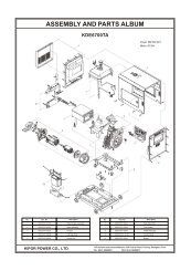
2. COMPONENT LOCATIONS2.1 Outside viewSpark Plug Carbon CanisterControlOil Dipstick PanelService Door InletBattery Air FilterFuel Level IndicatorFuel Filler CapAir Quality IndexStarter Grip Air ExhaustMuffler Warning3
3. PRE-OPERATION CHECKBe sure to check the generator on a level surface with the engine stopped. Under no circumstancescan this generator be installed in an enclosed compartment.3.1 Engine Oil LevelUsing non-detergent oil or 2-stroke engine oil could shorten theengine's service life.Use a high-detergent, premium quality 4-stroke engine oil, certified tomeet or exceed U.S. automobile manufacturer's requirements for APIService Classification SG/SF.Select the appropriate viscosity for the average temperature in yourarea.SAE Viscosity GradesSingleviscosityMulti-viscosityAmbient TemperatureOpen the left maintenance cover. Remove and wipe the oil dipstick with a clean rag. Check the oil level byinserting the dipstick in the filler hole, tighten the dipstick and screw it out. If the oil level is below the end ofthe dipstick, refill with recommended oil to the top of the oil filler neck.Dipstick Upper limitLower limit6
Running the engine with insufficient oil can cause serious enginedamage.The Low Oil Alarm System will automatically stop the engine beforethe oil level falls below a safe limit. However, to avoid theinconvenience of an unexpected shutdown, it is still advisable tovisually inspect the oil level regularly.3.2 FuelFuel tank capacity- 3.1 gal (11.6 L)Use unleaded 87 octane regular grade automotive gasoline.If the fuel level is low, refill to the shoulder of the fuel strainer, see fig.4.Never use an oil/gasoline mixture or dirty gasoline.Avoid getting dirt, dust or water in the fuel tank.After refueling, tighten the fuel filler cap securely.Gasoline is extremely flammable and is explosive under certainconditions.Refuel in a well-ventilated area with the engine stopped. Keep allsmoking materials, sparks, and any other source of combustion awayfrom the generator during refueling.Do not overfill the fuel tank (there should be no fuel in the fillerneck).After refueling, make sure the fuel filler cap is closedproperly and securely.Be careful not to spill fuel when refueling. Spilled fuel or fuel vapormay ignite. If any fuel is spilled, make sure the area is dry beforestarting the engine.Avoid repeated or prolonged contact with skin or breathing of vapor.KEEP OUT OF REACH OF CHILDREN.Fuel surfaceFuel surfaceFuel filler capStrainer7
Gasoline containing alternate fuels:If you decide to use a gasoline containing ethanol, be sure its octane rating is no lower than thespecification. Do not use a blend that contains more than 10% ethanol. Do not use any gasolinecontaining methanol.3.3 Air CleanerCheck the air cleaner element to be sure it is clean and in good condition.Open the left side maintenance cover. Remove the air cleaner cover, remove the paper element fromthe air cleaner cover, and check the element, Replace the element if dirty or the filter paper is torn.Air cleaner baseAir filter element Air cleaner coverNever run the engine without the air cleaner. Rapid engine wear willresult from contaminants such as dust and dirt being drawn throughthe carburetor into the engine.8
4. STARTING THE ENGINEWhen starting the generator after adding fuel for the first time or afterlong term storage, or after running out of fuel, turn the fuel valve leverto the "ON" position, then wait for 10 to 20 seconds before startingthe engine.4.1 Starting Procedure4.1(a) Turn the fuel valve lever to the ON position.<strong>IG4300</strong> Fuel Switch9
4.1(b) Pull the choke knob out to the CLOSED positionDo not use the choke if the engine is already warm or the ambient air temperature is high. Choke knob4.1(c) Insert the engine key and turn the engine switch to ON position.Engine switch10
4.1(d) Electric Start: turn the engine switch to the START until the engine has started. Do not operatethe starter for more than 10 seconds.<strong>Manual</strong> Start: pull the starter grip lightly until resistance is felt then pull the starter grip brisklytoward the arrow as shown below.Starter gripEngine switchFig.9(a)Fig.9(b)Do not allow the starter grip to snap back. Return it slowly by hand.Do not let the starter rope rub against the generator body or the ropewill wear out prematurely.4.1(e) Push the choke knob in to the OPEN position as the engine warms up.Choke Knob11
4.2 High altitude operationAt high altitude, the standard carburetor air-fuel mixture will be excessively richPerformance will decrease, and fuel consumption will increase.High altitude performance can be improved by installing a smaller diameter main fuel jet in thecarburetor. If you always operate the generator at altitudes higher than 5000 feet or 1500 metersabove sea level, have your authorized dealer install a high altitude main jet.Even with suitable carburetor jetting, engine horsepower will decrease approximately 3.5% for each1000 feet or 305 meter increase in altitude. The effect of altitude on the horsepower will be greaterthan this if no carburetor modification is made.Operation of the generator at an altitude lower than the carburetor isjetted for may result in reducedperformance, overheating, andserious engine damage caused by an excessively lean air/fuelmixture. Be sure to have any modification reversed at lower altitudes.4.3 Ambient TemperatureGenerator output generally derates 1% for every 10° F (5.5° C) above 85° F (29° C). The normaloperating range of the generator is -20° to 113° F (-29° to 45° C).Do not operate the generator when the ambient temperature is below-20° F (-29°)Do not operate the generator when the ambient temperature is above113° F (45° C)12
5. GENERATOR USE5.1 Warnings and CautionsTo prevent electrical shock from faulty appliances, the generatorshould be grounded. Connect a length of heavy cable between thegenerator's ground terminal and an external ground source.Connections for standby power to a building's electrical system must be made by a qualifiedelectrician and must comply with all applicable laws and electrical codes. Improper connections canallow electrical current from the generator to back feed into the utility lines. Such back feed mayelectrocute utility company workers or others who contact the lines during a power outage; when utilitypower is restored, the generator may explode, burn, or cause fires in the building's electrical system.Do not connect this generator to an automatic transfer switch. Serious damage to the engine andinverter module may result.Limit operation requiring maximum power to 30 minutes.For continuous operation do not exceed the rated power of 2800 watts or 23.3 amps. Do not exceed the current limit specified for any one receptacle. Do not modify or use the generator for other purpose other than what it was intended. Also observethe following when using the generator:• Do not attempt to connect generators in parallel.• Do not connect an extension to the exhaust pipe.• Do not operate with any covers removed or in a closed compartment13
When an extension cable is required, make sure you use the proper size and length.• 16 Gauge Cords- Any 16 gauge cord between 0 and 100 feet long will adequately handle tool and applianceloads up to 10 amps• 14 Gauge Cords- a 14 gauge cord between 0 and 50 feet long will adequately handle loads between 10 and15 amps.• 12 Gauge Cords- If your load is between 10 and 15 amps and the length of the cord is 50 to 100 feet, you needa 12 gauge cord to safely power any tool. Keep the generator away from other electric cables or wires such as commercial power supplylines. You may use DC receptacle when using AC supply.5.2 AC <strong>Power</strong> ApplicationThe generator has the capability to provide 120V and 240V AC <strong>Power</strong>. It can do so simultaneouslydepending on the needs of the user. However, it is important to understand the receptacles, theircurrent limitations. and how to distribute power efficiently.120V 20A GFCI Receptacle20/240V 30A ReceptacleVoltage Selection Switch20V 30A ReceptacleThe GFCI (ground fault circuit interrupter) shuts off power to the protected receptacles if a ground faultor current imbalance between two conductors is detected. If the reset button pops out, the applianceconnected to the receptacle may be defective. If the appliance appears to be in good condition, pressthe reset button until a click is heard. This will restore power. If the reset button pops out again,14
disconnect all appliances disconnected immediately and have them inspected by a qualified electricianbefore attempting to use them again.Do not attempt to operate appliances if the ground fault circuit interrupter resetbutton pops out repeatedly during use.Only the ground fault circuit interrupter receptacle provides ground fault protection.5,3 Voltage Selection SwitchThe voltage selection switch has two positions: AC120V and AC120/240V.1. When the voltage selection switch is in the 120/240V position, the generator supplies both 120V and240V AC power. If you operate the generator with the switch in this position, the electric current islimited to 15 amps to the 120V receptacles although it can provide 15 amps at 240V from the120/240V receptacle.2. When the voltage selection switch in the 120V position, the generator supplies 120V AC only. It cansupply a full 30 amps to the 30 Amp receptacle or 20A to the GFCI receptacle. Total current is limitedto 33 amps at rated load.5.4 AC Operation1. Start the engine and make sure the green output indicator light comes on.2. Confirm that the appliance to be used is switched off then plug in the appliance.15
Be sure that all appliances are in good working order beforeconnecting them to the generator. If an appliance begins to operateabnormally, becomes sluggish, or stops suddenly, turn off thegenerator engine switch immediately. Disconnect the appliance andexamine it for signs of malfunction.5.5 Output and Overload IndicatorsThe green output indicator light will remain on during normal operatingconditions. If the generator is overloaded to the point that the max powerrating of 35.8 amps is exceeded or if there is a short in the connectedappliance, the output indicator will go out and the overload indicatorwill go on and current to the connected appliance will be shut off.Stop the engine if the overload indicator light comes ON and investigatethe overload source. The engine will continue to run even though it isnot producing any AC power. The engine must be stopped and then the generator restarted to resumenormal operation.The two 120V receptacles are rated at 20 and 30 amps respectively..Should this current be exceeded, the circuit protection device willactivate and cut all current to the receptacle. This will be indicated bythe push button popping out. Reduce the load to the receptacle andreset the circuit protector by pushing in the button.16
5.7 Air Conditioner OperationFor best results, the SMART throttle switch should be in the off position. Bring the generator to anormal operating temperature before applying the air conditioning load. Always allow a 2 minute waitperiod when manually cycling an air conditioner off and on. A longer wait period may be requiredunder unusually hot weather conditions. Additionally, all other loads should be turned off until the airconditioner has started and is performing normally. It is also important to follow the air conditionermanufacturer's instructions for starting and restarting for proper operation.Some air conditionermanufacturers offer a start capacitor as an extra cost option. The lack of a start capacitor can causethe air conditioner to draw too high a starting current and overload the generator. Contact your airconditioner dealer if you consistently have problems starting your air conditioner with the generator.5.8 DC <strong>Power</strong> ApplicationThe DC receptacle may be used for charging 12 volt automotive-type batteries only. It is not designedto operate DC motors. Output voltage is 15-30V.DC output will vary according to the position of theSmart throttle switch.a. Connect the charging cable to the DC receptacle of the generator and then to the battery terminals.To prevent the possibility of creating sparks near the battery, connectthe charging cable first to the generator then to the battery.Disconnect the cable first at the battery.Before connecting the charging cable to a battery that is installed in avehicle, disconnect the vehicle's battery ground cable. Reconnect thevehicle's ground cable after the charging cables are removed. Thisprocedure will prevent the possibility of a short circuit and sparks ifaccidental contact is made between a battery terminal and thevehicle's frame or body.Do not attempt to start an automobile engine with the generator stillconnected to battery. The generator may be damaged.Connect the positive battery terminal to the positive charging cord.Do not reverse the charging cables or serious damage to thegenerator and/or battery may occur.The battery gives off explosive gases: keep sparks, flames andcigarettes away. Provide adequate ventilation when charging.18
The battery contains sulfuric acid (electrolyte). Contact with skin oreyes may cause severe burns.Wear protective clothing and a faceshield.A. If electrolyte gets on your skin, flush with water.B. If electrolytes gets in your eyes, flush with water for at least 15minutes and call a physician. Electrolyte is poisonous.If swallowed, drink large quantities of water or milk and follow withmilk of magnesia or vegetable oil and call a physician. Keep out of reach of children.The DC output is to be used to charge batteries only. Seriousdamage to the stator windings can occur if connected to a DC motoror transformer.b. Start the generator. The DC receptacle may be used while the AC power is in use. The DC receptacle is protected from an overload with a fuse. If the DC circuit is overloaded, the 5amp fuse will blow and power to the DC receptacle will cease. The red light on the DC panel willilluminate. The fuse is located to the left of the receptacle and is accessed by snapping open the accessdoor. Replace the fuse with one of the same capacity. Using a higher rated fuse may cause damage tothe generator alternator. 5 amp fuse Access door19
5.9 Low oil alarm systemThe low oil alarm system is designed to prevent engine damage caused by an insufficient amount of oilin the crankcase. Before the oil level in the crankcase falls below a safe limit, the low oil alarmsystem will automatically shut down the engine (the engine switch will remain in the ON position).If the low oil alarm system shuts down the engine the red low oil alarm indictor light will come on whenyou operate the starter, and the engine will not run. If this occurs, search for any oil leaks. Add engineoil to resume normal operation.5.9 Digital Display PanelThe generator features a digital panel that displays operating parameters and service reminders.Pressing the button will cycle the display through voltage, current, frequency, battery voltage, andaccumulated hours. Push the button to read the desired parameter.Operating ParametersParameter Reading Selector1 240VWith the voltage switch in the 120V position, the parameters are as follows:1. AC voltage expressed in volts2. Current expressed in amps3. Frequency expressed in Hertz4. Accumulated operating hours4. Battery voltage expressed in DC volts20
With the voltage switch in the 120/240V position, the parameters will be different as the display looksat both 120V AC legs1 . Total Voltage (both legs)2. Single Voltage leg A3. Single Voltage leg B4. Leg A current value5. Leg B current value6. Frequency7. Accumulated operating hours8. Battery VoltageService Reminders:When the specified service interval is reached, the display the following codes:SV1 Change oilSV2 N/A (diesel models)SV3 Service air cleanerSV4 N/A (diesel models)SV5 Adjust valve clearanceSV6 Check fuel tank and fuel linesTo see the prescribed service intervals, see chapter 7, Maintenance.When a service reminder is displayed, you can press the selection button to restore the operatingparameter however the service code will be displayed again in two seconds. After the specifiedmaintenance item is addressed, the code can be cleared by holding down the selection button for fiveseconds and the service interval clock will be reset.Do not ignore the service reminder and have the scheduled preventivemaintenance performed.. Serious engine damage may result otherwise.21
6. STOPPING THE ENGINE6.1 Normal Shutdown1. Switch off the connected equipment and disconnect from the generator.2. Turn off the engine switch.3. Turn the fuel valve lever to the OFF position.6.2 Emergency StopTurn the start switch to the OFF position.Continually stopping the generator with a load applied can lead todamage of the control module.22
7. MAINTENANCEThe purpose of the maintenance and adjustment schedule is to keep the generator in the bestoperating condition.Shut off the engine before performing any maintenance. If the enginemust be run, make sure the area is well ventilated. The exhaustcontains poisonous carbon monoxide gas.Use genuine <strong>Kipor</strong> parts or the equivalent. The use of replacementparts which are not of equivalent quality may damage the generator.7.1 Emission Control SystemEmission sourceExhaust gas contains carbon monoxide, nitrous oxide (NOx), and hydrocarbons. It is very important tocontrol the emissions of NO X and hydrocarbons as they are a major contributor to air pollution. Carbonmonoxide is a poisonous gas. The emission of fuel vapors is a source of pollution as well. The <strong>Kipor</strong>generator engine utilizes a precise air-fuel ratio and emission control system to reduce the emissionsof carbon monoxide, NO X , hydrocarbons, and evaporative fuel emissions.RegulationYour engine has been designed to meet current Environmental Protection Agency (EPA) and theCalifornia Air Resources Board (CARB) clean air standards. The regulations dictate that themanufacturer provide operation and maintenance standards regarding the emission control system.Tune up specifications are provided in the Specifications section and a description of the emissioncontrol system may be found in the appendix to this manual, Adherence to the following instructionswill ensure your engine meets the emission control standards.ModificationModification of the emission control system may lead to increased emissions. Modification is definedas the following: Disassembling or modifying the function or parts of the intake, fuel or exhaust system. Modifying or destroying the speed governing function of the generator.23
Engine faults that may affect emissionAny of the following faults must be repaired immediately. Consult with your authorized <strong>Kipor</strong> servicecenter for diagnosis and repair: Hard starting or shut down after starting Unstable idle speed Shut down or backfire after applying an electrical load Backfire or afterfire. Black smoke and/or excessive fuel consumptionReplacement parts and accessoriesThe parts making up the emission control system applied to <strong>Kipor</strong> engine have been specificallyapproved and certified by the regulatory agencies. You can trust the replacement parts supplied by<strong>Kipor</strong> have been manufactured to the same production standard as the original parts. The use ofreplacement parts or accessories which are not designed by <strong>Kipor</strong> may affect the engine emissionperformance. The manufacturers of replacement parts and accessories have the responsibility toguarantee that their replacement products will not adversely affect emission performance.MaintenanceMaintain the generator according to the maintenance schedule in this section. Service items morefrequently when used in dusty areas, or under conditions of high load, temperature, and humidity.Air Quality Index (only for California certified models)CARB requires that an air quality index label be attached to every certified engine showing the engineemission information for the emission duration period. The label is provided for the user to comparethe emission performance of different engines. The lower the air index, the better the engine emissionperformance. The description of durability is helpful for the user to learn the engine emission durationperiod and the service life of emission control system. Refer to the warranty section of this owner’smanual for more information.24
7.2 Maintenance Schedule(1) REGULAR SERVICE PERIODPerform at every indicated monthly oroperating hour interval whicheveroccurs firstITEMEngine oilCheckEACHUSEFIRSTMONTHOR20HRSEVERY 3MONTHSOR50HRSEVERY 6MONTHSOR100HRSEVERYMONTHSOR300HRSChange Air cleanerCheckClean/replace(2)Spark plug Clean/adjust Spark arrester Clean Fuel sediment cup Clean Valve clearance Check/adjust (3)Fuel tank and strainer Clean (3)Fuel lines Check Every 2 years (Replace as necessary) (3)NOTE: (1) Log hours of operation to determine proper maintenance.(2) Service more frequently when used in dusty conditions.(3) These items should be serviced by an authorized KIPOR service center unless the owner has theproper tools and is mechanically proficient. Refer to the KIPOR Generator and Engine shop manuals.To locate a parts dealer in North America, visit the website www.kipornorthamerica.com.7.3 Changing oilDrain the oil while the engine is still warm to assure rapid and complete drainage.Upper limit25Lower limit
Oil drain boltOil dipstick1. Open the left side maintenance cover.2. Remove the oil dipstick.3. Remove the drain bolt and drain the oil. There is a rubber plug in the bottom of the generator panthat can be removed to facilitate draining the oil. The generator will have to be raised off the groundand supported while the oil drains. Retighten the bolt securely.4. Refill with the recommended oil and check the level.5. Close the left side maintenance cover.7.4 Air cleaner serviceA dirty air cleaner will restrict airflow to the carburetor and allow dirt into the engine. Service the aircleaner regularly. Service more frequently when operating the generator in extremely dusty areas.Do not use gasoline or low flashpoint solvents for cleaning. Theyare flammable and explosive under certain conditions. Never run the generator without the air cleaner. Rapid engine wearmay result.26
Air Filter BaseFilter Element Air Filter CoverEleElementFilter1. Open the service door.2. Unsnap the clips and remove the air cleaner cover.3. If the paper element is dirty or torn, replace it with a new one. Do not attempt to clean the element.5. Reinstall the air cleaner cover.6. Close and latch the service door.7.5 Spark plug serviceRecommended spark plug: WR7DCTo ensure proper engine operation, the spark plug must be properly gapped and free of deposits.1. Open the service door.2. Remove the spark plug cap.3. Use the wrench to remove the spark plug.4. Clean any dirt from around the spark plug base.Spark plug wrench27
5. Visually inspect the spark plug. Discard it if the insulator is cracked or chipped.Clean the spark plug with a wire brush if it is to be reused.6. Measure the plug gap with a feeler gauge. The gap should be 0.028-0.031in (0.7-0.8mm). Correctas necessary by carefully bending the side electrode.Plug gap7. Install the spark plug carefully, by hand, to avoid cross-threading.8. After a new spark plug has been seated by hand, it should be tightened 1/2 turn with a wrench tocompress the sealing washer. If a used plug is being reinstalled, it should only require 1/8 to 1/4 turnafter being seated.9. Reinstall the spark plug cap.10. Close and latch the service door.The spark plug must be securely tightened. An improperly tightenedplug can become very hot and possibly damage the generator.Never use a spark plug with an improper heat range.7.6 Spark arrester maintenance28
1. Remove the generator rear cover to access the spark arrestor.2. Remove the spark arrestor from the muffler by unscrewing the clamp.3. Clean the spark arrestor with a stiff wire brush.4. Replace if the wire mesh is perforated or torn.5. Reinstall the spark arrester.6. Reinstall rear cover.7. TRANSPORTING/STORAGEIf the generator has been running, the muffler will be very hot. Allow itto cool before proceeding.The spark arrester must be serviced every 100 hours to maintain itsefficiency.Inspect the spark arrester screen for holes or tears. Replace asnecessary.8.1 TransportingWhen transporting the generator, turn the fuel valve lever OFF and keep the generator level to preventfluid spillage. Fuel vapors or spilled fuel may ignite. Transporting the generator with gasoline in the fueltank is prohibited.8.2 Extended Storage:1. Be sure the storage area is free of excessive humidity and dust.2. Drain the fuel.a. Open the left side maintenance cover.b. Turn fuel valve lever to ON and then loosen the carburetorDrainplugdrain screw. Drain the gasoline from the carburetor and fuel tankinto a suitable container.c. Tighten the carburetor screw, close the fuel valve lever and left side maintenance cover.g3. Once a month, recharge the battery.4. Change the engine oil.29
5. Remove the spark plug and pour a tablespoon of clean engine oil into the cylinder. Crank the engineseveral revolutions to distribute the oil and then reinstall the spark plug.6. Slowly pull the starter grip until resistance is felt. At this point, the piston is coming up on itscompression stroke and both the intake and exhaust valves are closed.Storing the engine in this position will help protect it from internal corrosion.8.3 Fuel Treatment and Generator Exercise:Any small engine is very susceptible to fuel varnishing. Fuel systems have very small orifices andpassageways which can easily become clogged by fuel residue that takes the form of gum and varnish.This can lead to hard starting and rough running and possibly cause the engine not to start at all. AsEPA regulations dictate no kits available to renew a carburetor, carburetor replacement will benecessary. Fuel preservatives are readily available at leading RV and marine dealers. Regularly adda fuel preservative to the generator fuel tank or fuel supply. Drain the carburetor bowl prior to anystorage period longer than 30 days. Exercise the generator by running it at a 50% load for twohours every month. This insures fresh fuel is run through the fuel system and prevents varnishing. Inaddition, seals and engine components are lubricated and the chance of carbon buildup in the uppercylinder head is lessened. Any moisture that has accumulated in the generator windings is baked outas well as keeping the battery charged.30
9. TROUBLESHOOTINGWhen the engine will not start:Is there fuel in the tank?YESIs the engine switch on?YESIs the fuel valve on?YESIs there enough oil in the engine?NONONONORefill the fuel tank.Turn the engine switch on.Turn the fuel valve on.Add the recommended oil.Is there a spark fromthe spark plug?YESNOReplace thespark plugStill no sparkTake the generator toan authorized KIPORservice center.. Be sure there is no spilledfuel around the spark plug. Spilledfuel may ignite.Is the fuel reaching the carburetor?If the engine still does not start, takethe generator to an authorized <strong>Kipor</strong>service center.To check:1) Remove the spark plug cap and clean anydirt from around the spark plug.2) Remove the spark plug and install the sparkplug in the plug cap.3) Set the plug side electrode on the cylinderhead to ground.4) Crank the engine; sparks should jump acrossthe gap.To check:1) Turn off the fuel valve and loosen the drainscrew.2) Fuel should flow from the drain when the fuelvalve is turned on.31
AC Appliance does not operate:Is the output indicator light ON?YESNOIs the overload indicatorlight ON?NOTake the generator to a <strong>Kipor</strong>service center.YESCheck the electrical appliance orequipment for any defects.NOTake the generator to anauthorized KIPOR service center.YES Replace the electricalappliance or equipment.Take the electrical applianceor equipment to an electricalshop for repair.No output at the DC receptacle:Is the fuse blown?YESReplace the fuse.NOTake the generator to anauthorized KIPOR servicecenter.32
10. SPECIFICATIONSModel<strong>IG4300</strong>TypeInverterRated Voltage 120/240FrequencyMaximum OutputRated OutputDC OutputEngine ModelEngine TypeDisplacement60 HZ4300W, 35.8A/17.9A4000W, 33.3A/16.7A12V@5.0AKG2804 Stroke, overhead valve, single cylinder277 ccCompression Ratio 8.5:1Rated <strong>Power</strong>Cooling SystemIgnition SystemOil Capacity5.5 HP @ 3600 RPMForced AirTransistorized1.2 qt (1.1L)Fuel Tank Capacity 3.1 gal (11.6 L)Rated Load Run TimeNoise level-no load-full load @ 23’ (7m)Spark PlugLengthWidthHeightWeightTune Up SpecificationsSpark Plug GapValve Clearance- cold (Intake)Valve Clearance- cold (Exhaust)5 hours62-67 dBWR7DC30.9 in (785 mm)18.5 in (470 mm)22.4 in (569 mm)162 lbs (72.5 kg)0.024-0.028 in (0.6-0.7 mm)0.0039 ±.0008 in (0.10 ± 0.02 mm)0.0059 ± .0008 in (0.10 ± 0.02 mm)33
11. WIRING DIAGRAM34
12. WHEEL KIT1. Axle shaft2. 2.5’ swivel locking wheel3. Bolt M8X 164. Wheel5. Bolt M6X1635
A Wheel Assembly Installationa. Install the left and right axle platesb. Insert axle through the platec. Install an iiner washer, the wheel,and an outer washerd. Secure with a cotter pin 1. Wheel2. Axle3. Cotter Pin4. WasherB. Install the locking swivel wheela. Align the hole in the wheel plate with the predrilled holes in the chassisb. Secure with 4 M6X16 bolts1. 2.5’ locking swivel wheel2. M6X16 bolt36
13. WARRANTY13.1 <strong>Kipor</strong> <strong>Power</strong> Equipment Limited WarrantyLENGTH OF WARRANTYGenerators are covered by this warranty from the date of original retail purchase for a period of two years for residentialuse and one year for commercial applications. Units used in rental fleets or as demonstration models will be consideredcommercial usage. Starting batteries included with a generator are warranted for a period or one year by themanufacturer. <strong>Kipor</strong> must warrant the emission control system for a period of two years provided there has been noimproper maintenance, abuse or neglect. See the emission control warranty in the section immediately following thelimited warranty description. The warranty coverage is continual from the original date of purchase, and does not restartupon the replacement of any part or complete unit. Individual parts replaced at any point during the warranty periodare only eligible for warranty coverage for the balance of the original warranty period.ELIGIBILITYTo be eligible for warranty service, the product must be purchased in the United States or Canada from an authorizeddealer. This warranty applies to the original retail purchaser only and is not transferable. Proof of purchase is required.Goods exported from North America as well as goods sold at auction are excluded from warranty coverage. Warrantycoverage will only be provided by authorized dealers in the United States and Canada.COVERAGEParts, labor and regular shipping costs will be covered for any failure that is proven to be a failure of material orworkmanship under normal use during the applicable warranty time period. It is the responsibility of the end user toreturn the product to the nearest authorized repair center as directed by the warranty administration center. In the eventthat the generator is deemed not repairable or the necessary repair would be economically unfeasible, the <strong>Kipor</strong>distributor will pay for shipping of the unit from the repair center to the designated distributor facility and the shipping ofa replacement unit. <strong>Kipor</strong> or its distributor reserves the right to repair or replace these parts at its option. The return ofdefective parts may be requested.. Anything replaced under warranty becomes the property of <strong>Kipor</strong>..TO OBTAIN WARRANTY SERVICEContact any authorized dealer or contact our national customer service center at:Phone( 503)445-0199 E-mail: service@kiporpowersystems.comIf contacting us by e-mail, be sure to include a description of the problem as well as all return contact information suchas address, phone number, fax number, e-mail, etc. Engine serial number and proof of purchase are required.EXCLUSIONSThis warranty does not extend to parts affected or damaged by accident and/or collision, normal wear, fuelcontamination or degradation, use in an application for which the product was not designed or any other misuse,neglect, incorporation or use of unsuitable attachments or parts, unauthorized alteration, or any causes other thandefects in material or workmanship. This warranty does not extend to normal maintenance items such as belts, hoses,spark plugs and filters past the first scheduled replacement or service interval for these items, whichever comes first.Coast will pay for minor adjustments for a period of ninety days from the purchase date of the generator.DISCLAIMER OF CONSEQUENTIAL DAMAGE AND LIMITATION OF IMPLIED WARRANTIES<strong>Kipor</strong> denies any responsibility for loss of time or use of the product, transportation, commercial loss, or any otherincidental or consequential damage. Any implied warranties are limited to the duration of this written limited warranty.Some states do not allow limitations on how long an implied warranty lasts and/or do not allow the exclusion orlimitation of incidental or consequential damages. Therefore, the above exclusions and limitations may not apply toyou. This warranty gives you specific legal rights and you may also have other rights which vary from state to state.37
13.2 Emission Control System WarrantyWarranty Statement• The U.S. Environmental Protection Agency (EPA) and the California Air Resources Board (CARB) requiremanufacturers of small off-road engines to warranty their products with a two year warranty for thosecomponents that are specified as being part of the emission control system. <strong>Kipor</strong> <strong>Power</strong> Equipment, EPA,CARB offer the following explanation of the Emission Control Warranty.• In the United States and California, new small off-road engines must be designed, built, and equipped to meetstringent emission standards. <strong>Kipor</strong> must warrant the emission control system on your generator engine for theperiods of time listed below provided there has been no abuse, neglect, improper maintenance, orunauthorized application of your small off-road engine.• If a warrantable condition is determined, <strong>Kipor</strong> <strong>Power</strong> Equipment will repair your small off-road engine at nocost to you including diagnosis, parts, and labor.CoverageEmissions control parts on the engine are warranted for a period of two years, subject to provisions set below. If anycovered part on your engine is defective, the part will be repaired or replaced by <strong>Kipor</strong> <strong>Power</strong> Equipment.Owner’s ResponsibilitiesYou are responsible to maintain the engine as defined in your <strong>Kipor</strong> Generator Owner’s <strong>Manual</strong>. <strong>Kipor</strong> recommends thatyou retain all record/receipts covering maintenance on your engine but <strong>Kipor</strong> <strong>Power</strong> Equipment cannot deny warrantyclaims based on the lack of receipts or for your failure to perform all scheduled maintenance. You may be deniedwarranty coverage if a part has failed due to abuse, neglect, improper maintenance, or unapproved applications.You are required to bring your generator to an authorized <strong>Kipor</strong> generator dealer for repairs as soon as a problem exists.For emissions warranty service, contact your nearest dealer. A listing is available fromservice@kiporpowersytems.com or by calling (503) 445-0199.Emission Control System PartsCoverage under this warranyt extends only to the emissions control parts listed below:1. Fuel SystemA. Carburetor gasketsB. Fuel lines, fittings, and clampsC. Fuel filter (if equipped)D. Fuel pump (if equipped)E. Carburetor2. Intake SystemA. Air cleaner assemblyB. Intake manifold3. Ignition SystemA. Ignition coilB. Spark plug4. Exhaust SystemA. Catalytic converter (if equipped)B. Exhaust manifold38
C. Gaskets5. Crankcase Breather SystemA. Breather assemblyB. Breather tube6. Air Injection SystemA. Secondary air injection valve7. Fuel Tank Evaporative Emissions Control SystemA. Fuel tankB. Fuel capC. Carbon canister and brackets8. Miscellaneous Items used in aboveA. Hoses, connectors, and fittingsB. Electrical switchesWarranty Provisions1. Claims Warranty claims shall be filed in accordance with the provisions of the <strong>Kipor</strong> warranty and policiesestablished with the authorized repair center network.2. Exclusions Warranty coverage shall be denied for failure of an emissions control system part caused by abuse,neglect, improper maintenance or application as described in the <strong>Kipor</strong> Generator Owner’s <strong>Manual</strong>. Additionally,coverage may be denied for the use of add-on parts, modified parts, or parts that are not equivalent to original <strong>Kipor</strong>generator parts in performance and durability.3. Length of Coverage <strong>Kipor</strong> <strong>Power</strong> Equipment warrants to the original retail purchaser and each subsequent ownerthat the emissions control system shall be free of defects in materials and workmanship for a period of two years fromthe date of the original retail customer.4. Repair or Replacement Cost Repair or replacement of any emissions control system part will be repaired at nocharge to the owner including diagnostic labor which would determine an emissions control system defect exists if therepair is performed at an authorized <strong>Kipor</strong> repair center.5. Consequential Damage Repairs will extend to any other engine part damaged by the failure of any emission controlsystem part.6. Maintenance The emissions control system and associated parts are warranted for defects during the warrantyperiod only.The warranty does not cover any replacement of parts that are replaced as required by the maintenance schedule in the<strong>Kipor</strong> Generator Owner’s <strong>Manual</strong>. Any replacement part that is equivalent in function and durability may be used formaintenance or repairs.QuestionsIf you have any questions regarding your rights and responsibilities under this emissions system warranty, you maycontact the <strong>Kipor</strong> Aftermarket Support office.By email: service@kiporpowersystems.comBy phone: (503) 445-0199By mail: <strong>Kipor</strong> <strong>Power</strong> EquipmentAttn: Aftermarket Support12021 NE Airport Way Ste. EPortland, OR 9722039
14. EMISSION CONTROL SYSTEMIf so designated, your generator has an engine that has been approved by the California AirResources Board. Other than the tune up procedures specified in the maintenance section, noadditional maintenance is required.The emission control system has the following components:1. Fuel System: The fuel tank, cap, indicator and hoses are specially designed and constructedto not allow fuel vapors to permeate and be released to the atmosphere.2. A carbon activated canister collects gasoline vapors from the fuel tank and returns them to thecombustion chamber for burning.3. A catalyst is built into the muffler to further treat the engine exhaust.4. A secondary air injection valve adds combustion air to ignite unburned fuel in the exhaust.Contact your authorized <strong>Kipor</strong> service center to obtain the correct replacement parts and service onthis system.CanisterconnectionAir filter housingFlange nut M6Filter elementCarburetorMain metering jetAir filter coverInlet System41
Fuel System42
Generator FrameCanisterService Door SideCarbon Canister Location SecondaryValve GasketBoltAirMuffler withCatalystSpark Arrestor Gasket Connection toexhaust manifold43
Exhaust System44