ig6000 service - Kipor Power Systems
ig6000 service - Kipor Power Systems
ig6000 service - Kipor Power Systems
- No tags were found...

Create successful ePaper yourself
Turn your PDF publications into a flip-book with our unique Google optimized e-Paper software.
<strong>Kipor</strong> <strong>Power</strong> <strong>Systems</strong> August 1, 2011IG6000IG6000hGenerator Service Manual
PrefaceThis manual covers the construction, function and servicing procedure of the KIPOR KGE7000Ti singlevoltage generator and the dual voltage KGE6000Ti and IG6000 generator. This manual covers generatorspecifications, function, troubleshooting and repair.Careful observance of the instructions contained in this manual will result in safe and quality <strong>service</strong>work.All information, illustrations, directions and specifications included in this publication are based on thelatest product information available at the time of printing.KIPOR POWER CO., LTD, reserves the right to make changes without incurring any obligation whatever.No part of this publication can be reproduced without written permission.
TABLE of CONTENTS1. Specifications.........................................................................................................................................1.1 General Specifications..................................................................................................................1.2 Generator Specifications..............................................................................................................1.3 Performance Curves......................................................................................................................1.4 Dimensional drawings................................................................................................................1.5 Wiring Diagram.......................................................................................2. Service and Maintenance …………………………………………………………………………………….2.1 The Importance of Proper Service .……………………………………………………………………...2.2 Safety Precautions .…………………………………………………………………………………….....2.3 Service Rules.................................................................................................................................2.4 Serial Number and Bar Code Location......………………………………………………………......2.5 Engine Service Standards..........................................................................................2.6 Fastening Torques .…………………………………………………………………………………….2.7 Troubleshooting.…………………………………………………………………………………………..3. Inspection and Adjustment...................................................................................................................3.1 Maintenance Schedule.................................................................................................................3.2 Engine Oil.....................................................................................................................................3.3 Low Oil alarm ...............................................................................................................3.4 Air Cleaner...................................................................................................................................3.5 Spark Plug...................................................................................................................................3.6 Valve Clearance. .........................................................................................................................3.7 Fuel Switch/Fuel Filter.................................................................................................................4. Air Cleaner/Muffler...............................................................................................................................4.1 Air Cleaner....................................................................................................................................4.2 Muffler...........................................................................................................................................4.3 Air vent pipe and second gulp valve…………………………………………………5. Carburetor ...........................................................................................................................................5.1 Disassembly and Reassembly......................................................................................................5.2 Inspection.......................................................................................... . . . . . . .. . .. . . . . . . . . . . . .6. Control Panel, charging adjustor, timing relay, Ignition control module, inverter Module.....................6.1 Disassembly and Reassembly.....................................................................................................6.2 Inspection............................................................................................................................7. Housing group and Fuel Tank........................................................................................................7.1 Disassembly and Reassembly (IG6000)......................................................................................7.2 Disassembly and Reassembly(IG6000h)....................................................................................7.3 Vaporize control system……………………………………………… …………………..8. Alternator, Ignition Coil, Trigger, electric motor, air guide cover..........................................................8.1 Air guide cover, cylinder end cover, cylinder bottom cover air guide plate, electric motor............8.2 Ignition Coil and Trigger................................................................................................................8.3 Alternator.....................................................................................................................................9. Cylinder cover, valve..........................................................9.1 Disassembly and Reassembly.....................................................................................................9.2 Inspection............................................................................................................................10. Crankcase cover, Crankshaft, Camshaft, Piston, Connecting rod..............................................10.1 Disassembly and Reassembly.....................................................................................................10.2 Inspection............................................................................................................................1
1.SPECIFICATIONS and DIAGRAMS1.1 General SpecificationsDimensions and weightsModelIG6000Overall length- in. (mm) 31.6 (802)Overall width- in. (mm) 19.4 (498)Overall height- in. (mm) 24.6 (624)Dry weight- lbs. (Kg) 213 (96.7)EngineModelKG390GETiType4-stroke,OHV, single cylinderDisplacement- cu.in. (cc) 23.7 (389)Bore x stroke- in. (mm) 3.46 x 2.51 (88×64)Maximum horsepower(KVA) 7.7/3600Compression ratio 8.5:1Cooling systemIgnition systemIgnition timingSpark plugCarburetorAir cleanerGovernorLubrication systemForced airTransistorized controlled ignition25°B.T.D.CWR7DCHorizontal float & fly typeDry replaceable elementInverter module controlForced splashOil capacity- qt. (L) 1.2 (1.1)Starting systemStopping systemFuelElectric starterElectric groundAutomotive unleaded gasolineGeneratorModelGenerator typeGenerator structureExcitationVoltage regulation systemPhaseRotating directionFrequency regulationKD70Multi pole rotation typeSelf-ventilation drip-proof typeSelf-excitation (Magnet type)Pulse Width ModulationSingle phaseClockwise (Viewed from the generator)AC-DC-AC conversion (Inverter type)2
1.2 Generator SpecificationsModelIG6000Maximum output(AC)6.0 KVARated output (AC)5.5 KVARated frequency (HZ) 60Rated voltage(AC) 120/240Maximum current (amp) 50/25Rated current(amp) 45.8/22.9Rated voltage(DC)12VRated current(DC)5A<strong>Power</strong> factor 1.0MomentaryMax.10%Voltage variationAverageMax.1.5%rateAverage timeMax. 3 secondsVoltage stability ±1%Momentary Max. 1%FrequencyAverage Max. 1%variation rateAverage timeMax. 1secondFrequency stability ±0.1%Insulation resistanceMin. 10MΩAC circuit protector- Amps 120/240 VAC 51.7/25.8DC circuit protector7AFuel tank capacity- gal (L) 5.4 (20)Operating hours at rated load 5.5Noise level dB @23’ (7 m) no load-full load 65-753
1.3 PERFORMANCE CURVESThe curves show performance of the generator under average conditions. Performance may varydepending upon ambient temperature, altitude and humidity.●AC External characteristic curves● DC External characteristic curves4
1.5 Wiring Diagrama. Single voltage output5
. Double-voltage output6
2. SERVICE and MAINTENANCE2.1 The importance of proper servicingProper servicing is essential to the safety of the operator and the reliability of the generator. Any erroror oversight made by the technician while servicing can easily result in faulty operation and/or damage tothe equipment or injury to the operator.!WarningImproper servicing can cause an unsafe condition that can lead to serious injury or death.Follow the procedures and precautions in this shop manual carefully.Some of the most important precautions are stated below. But we could not list all the potential danger,you should judge yourself if it need to do the maintenance task.!WarningCould not follow the maintenance instruction and safety precautions can cause an unsafe condition thatcan lead to serious injury or death. Follow the procedures and precautions in this shop manual carefully.2.2 Safety PrecautionsBe sure you have a clear understanding of all basic shop safety practices and that you are wearingappropriate clothing and safety equipment. When performing maintenance or repairs, be especiallycareful of the following:• Read the instructions before you begin, and be sure you have the tools and skills required toperform the tasks safely.• Be sure that the engine is off before you begin any maintenance or repairs. This will reduce thepossibility of several hazards:- Carbon monoxide poisoning from engine exhaust.- Run engine in the ventilated place whenever.- Burns from hot parts.-Touch the engine parts after it cooled.- Injury from moving parts.• Do not run the engine unless the instructions tell you to do so. Keep your handsand clothing away from rotating parts.• To reduce the possibility of fire or explosion, exercise extreme caution whenworking around gasoline. Use only a nonflammable solvent, not gasoline, to cleanparts. Keep cigarettes, sparks and flames away from all fuel-related parts.7
2.3 Service Rules• Use genuine KIPOR or KIPOR recommended parts and lubricants or their equivalents. Parts thatdo not meet KIPOR’s design specifications may damage the engine and void the warranty.• Use special tools designed for the product when specified.• Always install new gaskets, O-rings, etc. when reassembling components.• When tighten the bolt or nut, please from major diameter to minor diameter, from inside tooutside. Tighten the bolt and nut to the specific torque in this way.• Clean parts in cleaning solvent upon disassembly. Lubricate any sliding surfaces beforereassembly.• After reassembly, check all parts for proper installation and operation.• Many screws used in this machine are self-tapping. Be aware that cross-threading or overtightening these screws will strip the threads and ruin the hole.• Use only metric tools when servicing this engine. Metric bolts, nuts and screws are notinterchangeable with non-metric fasteners. The use of incorrect tools and fasteners will damagethe engine.• Be sure to follow the mark and instruction of the book when use the tools.■ Electrical Precautions• Hold the connector body to disconnect the connector. Do not disconnect by pulling the wireharness. To disconnect the locking connector, be sure to unlock first, and then disconnect.• Check the connector terminals for bend, excessive extrusion, missing terminals, or otherabnormalities before connecting the connector.• To connect, insert the connector as far as it goes. If the connector is a locking type, be sure that itis locked securely.• Check the connector cover for breakage and check whether the connector female terminal is notopened excessively. Then, connect the connector securely. Check the connector terminal for rust.Remove the rust using an emery paper or equivalent material before connecting the connector.• Set the harness clips in the specified places of the frame securely, and secure the wireharnesses.• Clamp the cables securely.8
• Clamp the wire harnesses securely so that they do not interfere with the rotating parts, movingparts and hot parts.• Route and connect the wire harnesses properly. Be sure that the harnesses are not slack,twisted or pulled overly taut.• Route the wire harnesses properly so that they do not contact sharp edges and corners and theend of the bolts and screws on the body.• If a wire harness must contact the end of the bolts or screws or sharp edges and corners, protectthe contact part of the harness with a loom or by winding with electrical insulating tape. If the wireharness has a grommet, set the grommet securely.• Take care not to pinch the wire harnesses during installation of a part. If a wire harness hasdamaged insulation, repair by winding with electrical insulating tape.• When using an electrical tester like a volt/ohm meter or clamp on meter, read the manufacturer’soperating instructions carefully before operating the tester. Be sure that the tester battery is fullycharged and the meter is functioning properly2.4 Serial Number and Bar Code LocationThe engine serial number is stamped beside the engine oil drain plug. This number is used to identify thespecific engine version.Engine serial number9
2.5 Maintenance standards of enginePart Item Standard in. (mm) Service limitEngine Max. speed under zero load (rpm) ≤3780rpmCylinder pressure0.55MPa/600rpmCylinder Cylinder sleeve I.D. 88.015~88.035 88.17PistonPiston skirt O.DPin bore I.D.87.96~87.9820.002~20.00887.8520.05Piston pin O.D 19.994~20.000 19.95Height h 1.97~1.99 1.87First ring/second ringSide gap t 0.02~0.06 0.15Closed gap 0.2~0.35 1.0Piston ringThickness t 3.9~4.1 3.7Height h 2.68~2.75 2.58Oil ringSide gap t 0.055~0.14 0.20Closed gap 0.20~0.50 1.0Thickness t 2.9~3.3 2.8Connecting rodSmall end I.D20.007~20.02020.09Big end I.D36.015~36.02536.09Crankshaft Crank pin O.D. 35.960~35.975 35.90Valve clearance IntakeExhaust0.06±0.020.08±0.02Valve rod ODIntake6.570~6.5856.50ValveExhaust6.550~6.5706.50Vessel I.DIntake/Exhaust 6.600~6.6226.68Seat widthIntake/Exhaust 0.8~1.22.0Valve spring Free Length Intake/Exhaust 39 37.5Cam wheel Cam height I.D Intake32.60~32.8032.25Exhaust32.09~32.2931.75Camshaft O.D 15.984~15.966 15.920Valve tappet O.D 8.96~8.98 8.87Crankcase Valve tappet ID9.000~9.0159.06Camshaft Bearing I.D.16.000~16.01816.05Crankcase cover Camshaft Bearing I.D. 16.000~16.018 16.05Carburetor Main metering jet1.02—Floater height13Indicating bolt opening2 ringSpark plug Clearance 0.7—0.8 —Ignition coil Resistance Primary sideSecond side0.8—1.3Ω15—21kΩ——Pulse coilAir gap.020~.030 (0.5~0.75)—(Trigger)Resistance80~130Ω—Carburetor magnetResistance 6~8Ω —valve10
Alternator Maintenance StandardsStandard(Ω)Part Item Type120V/240V 120V 240VDouble-voltage Single voltageOrange-Ignition winding l Resistance Yellow/Green0.22~0.24Gray-orange 0.15~0.17ServicelimitExternalcharging windingBuilt-in chargingwindingResistance Blue-blue 0.03~0.04Resistance Purple-Purple 0.12~0.16Sub windingResistanceWhite-white(green-green)0.08~0.12Main windingResistanceBlack-black(red-red)0.45~0.60 0.09~0.10 0. 9~1.12.6 Fastening TorquesItemSpecificationN.mTightening torqueKgf.mConnecting rod bolt M8 20~22 2.0~2.2Cylinder cover bolt M10×1.25×80 42~46 4.2~4.6Spark plug M14×1.25×19 20~30 2.0~3.0Crankcase side cover M8×30 20~23 2.0~2.3Flywheel nut M18×1.5 120~130 12.0~13.0Rocker arm shaft bolt M8×16 20~23 2.0~2.3Adjusting nut of rockerarm shaftM6×0.75 8~10 0.8~1.0M5 bolt、nut 5~7 0.5~0.7Standard torqueM6 bolt、nut 8~10 0.8~1.0M8 bolt、nut 18~22 1.8~2.2M10 bolt、nut 35~45 3.5~4.5Note: Use standard torque values for fasteners not listed in this table.11
2.7 TroubleshootingThis section gives very general information regarding symptoms and possible causes. Refer tosubsequent sections regarding testing and removal and replacement of specific components andsystems. Engine overhaul is addressed in the IG6000 Engine shop manual.a. General symptoms and possible causesEngine does notstart or hardstartingEngine speeddoes not stabilizeFuel filter cloggedFuel hose cloggedFuel switch won’t operateCarburetor defectiveIgnition coil defectiveSpark plug defectiveTrigger defective or improper air gapSpark plug cap disconnectedOil alarm defectiveIgnitor defectiveIgnition coil defectiveOpening set of smart throttle improperTiming relay defectiveIgnition winding control module defectiveCarburetor faultyThrottle control stepping motor defectiveInverter unit defectiveValve clearance misadjustedCleanCleanReplaceClean and and adjustInspect and replaceInspect and replaceInspect and replaceInspect and replaceInstall securelyInspect and replaceInspect and replaceIn whole or semi locationInspect and replaceInspect and replaceClean and adjustInspect and replaceInspect and replaceReadjustb. Hard starting or no startCheck the fuel level in the tank →no fuel Add fuel and restart the engine↓Sufficient fuelCheck fuel switch is in ON position →off Turn on it and restart the engine↓onLoosen the drain screw and checkwhether fuel reaches bowl and whether →abnormalCheck the timing relay for damage and fuelsystem for blockagethe fuel level is normal↓normalRemove and check spark plug and checkCheck each carburetor hole and nozzle for→dryif electrode is wet or dryblockageClean and dry the carburetor and observe↓wet→choke action. if severe wet, check if any fuelleakage and if the floating valve is normal.Attach the spark plug on plug cap, ground →no spark Perform the ignition system troubleshooting12
the electrode on the cylinder head.; startthe engine and check the spark conditions↓normalInstall a compression gauge in the sparkplug hole and restart the engine andcheck the cylinder compression.↓normal compression (80 psi/.55 Mpa)Install the spark plug. Restart the engineaccording to the starting procedure.or weakspark→lowcylindercompression1. Check valve clearance;2. check cylinder head gasket for leakage.3. Check combustion chamber for excesscarbon buildup.4. check valve conical surface and valveseats.5. check piston, piston rings and cylinderfor worn.■ Cylinder compression check1. Remove the spark plug cap and spark plug2. Install a compression gauge in the spark plug hole. Pull the recoil starter rope several times with forceand measure the cylinder compression.Cylinder compression0.55Mpa/600rpmc. Ignition system troubleshooting■ Fill oil to the specified location before inspecting■ Please use the WR7DC spark plug■Spark plug inspection1. Remove spark plug2. Attach the removed spark plug to the plug cap3. Ground the negative electrode of the spark plug against the cylinder head or engine block and engagethe electric starter and check to see if a spark jumps across the electrode.!Warning■ Do not pull the recoil starter rope while touching the high tension wire with a wet hand. High voltage isgenerated which is dangerous.■ Make sure no spilled fuel is anywhere on the engine and no fuel is on the spark plug before testing.■ Keep sparks and any other combustible source away from the spark plug hole and engine metal casebefore installing and checking.13
Measure the spark plug gap and performthe spark test.Standard gap: .028-.034 in. (0.7-0.8 mm)↓no sparkPerform the spark test again using a new →normal Replace the spark plugspark plugspark↓no sparkPerform the spark test again using a new →normal Replace Ignitorignitorspark↓no sparkDisconnect low oil alarm and perform theReplace low oil alarm→abnormalspark test.↓no sparkCheck the ignition control moduleReplace the ignition module↓normalCheck resistance of motor ignition winding →abnormal Replace the motor rotor↓normalCheck trigger air gap and triggerAdjust the air gap and/or replace the trigger→abnormalresistance↓normalCheck the ignition coil resistance and highCheck the ignition coil→abnormalvoltage cable and insulation cap↓Check or replace wiring harnessd. Engine oil level is low, but engine does not stop.Drain out all engine oil, disconnect thelow oil alarm wire and check if the outletterminal is connected to ground↓conductiveConnect the alarm wire, loosen ignitionmodule receptacle and check if theorange wire is connected with the ground↓conductiveReplace ignition module→notconductive→notconductiveReplace the oil level alarm switchRepair or replace wiring harnesse. Engine speed does not increase or is unstableCheck air filter element for clog clogged Clean air filter element↓not cloggedCheck the valve clearance→abnormal Adjust the valve clearance↓normalRemove the spark plug and check theClean the spark plug and adjust the spark→abnormalelectrodes for carbon and spark plug gapplug gap or replace new spark plug14
↓normalCheck each carburetor hole and mainnozzle for blockage↓not cloggedCheck the air intake paper gasket andthe sealing of heat-insulation block ofcarburetor↓normalTest the cylinder compression↓normalPerform the throttle control systemtroubleshooting→clogged→abnormal→abnormalDisassemble and cleanTighten the nuts securely, replace thegasket or heat-insulation block1. Check the valve clearance2. Check combustion chamber for excesscarbon3. Check the piston, piston ring andcylinder for wear and damage.f. Engine stops after starting (the smart throttle is in proper position)Check the engine oil level and check ifAdd oil and restart the engine→oil leveloil level alarm activates when rotationalarmstops↓sufficient oilCheck the fuel in fuel tank →no fuel Add fuel and restart the engine↓sufficient fuelCheck for operation of fuel switch andClean the fuel switch and filter→cloggedblockage in fuel filter↓not cloggedCheck for blockage of fuel hoses →clogged Clean or replace the hoses↓not cloggedTurn the ignition switch to ON position,Replace the timing relay→ hascheck the timing relay for outputCheck each carburetor hole and mainnozzle for clogged↓normal fuel flowCheck the intake gasket and the sealingof carburetor heat-insulation block↓normalMeasure the cylinder compression→clogged→abnormal→abnormal15Disassemble and cleanTighten the nuts securely, replace thegasket or heat-insulation block1. Check the valve clearance2. Check if too much carbon in burningroom3. Check the piston, piston ring andcylinder for wear and damage.
↓normalCheck the trigger air gap↓normalPerform throttle control systemtroubleshooting→abnormal Readjust the clearanceg. Throttle control system troubleshooting1). Engine speed is too high or too lowCheck AC outputabnormalPerform the generator troubleshootingflowing the instruction of “No or Low ACoutput”↓normalCheck the stepping motor →abnormal Replace the stepping motor↓normalReplace the inverter unit2). The engine speed does not increase when smart throttle is on and load is increased.Check the AC outputPerform the generator troubleshooting→abnormal flowing the instruction of “No or Low ACoutput”↓normalCheck the stepping motor →abnormal Replace the stepping motor↓normalCheck the smart throttle switch →abnormal Replace the smart throttle switch↓normalCheck “Smart” switch connecting wire →abnormal Repair or replace the wire harness↓normalReplace the inverter unith. Low AC outputIs the overload indicator light ON? →on Disconnect the load, and restart the engine.↓offIs the engine speed normal?Perform the throttle control systemSmart switch operation:troubleshooting→abnormalOn: 2500±100rpmOff: 3600±100rpm↓normalStop engine and check the AC receptacle →abnormal Replace the receptacle↓normalCheck the AC output connector →abnormal Replace the connector↓normalCheck voltage selector switch(only forReplace selector switch→abnormaldouble voltage selector output)16
Disconnect the two 6P input connectorson the inverter unit. (6p for singlevoltage , 4p or 2p for double voltage)Disconnect spark plug cap or igniterconnector, measure the AC voltage ofmain winding and sub. Winding when thestator motor is running. Measure one ACvoltage of main winding or sub. Windingfor double voltage unit.Black – black: 〉30VWhite – white: 〉1VSingle voltage230/240V type:Black – black: 〉60VWhite – white: 〉1VSingle voltage 120V type:Black – black: 〉30VWhite – white: 〉1V↓normal (255 volts)Replace inverter unit→abnormal1. Check the wiring of the stator leads inthe harness. Repair or replace theharness.2. Rotor internal magnetic weaken,replace the rotor.i. No AC outputIs the engine speed normal?Perform the throttle control systemabnormaltroubleshooting↓normalCheck AC receptacles →abnormal Replace receptacles2.7.9↓normalCheck the rectifier →abnormal Replace the rectifier↓normalMeasure the resistance between twoblue wire on the rectifier →abnormalCheck and repair the wire harness orreplace the statorResistance:0.03~0.04Ω↓normalRotor losses excitation, replace the rotorj. Electric starter doesn’t run.Check the battery voltage →abnormal Replace the battery↓normalCheck ignition switch →abnormal Replace the ignition switch↓normalCheck the battery switch →abnormal Replace battery switch( sucking coil)↓normalCheck the starting motor →abnormal Replace the starting motor↓normalCheck and repair or replace main wireharness17
k. The battery doesn’t charge.Check ignition switch →abnormal Replace ignition switch↓normalCheck charging regulator →abnormal Replace the charging regulator↓normalMeasure resistance of charging coilwinding→abnormalCheck and repair electric wire harness orreplace stator.Resistance: 0.12~0.16Ω:↓Check and repair or replace wire harness18
3. INSPECTION AND ADJUSTMENT3.1 MAINTENANCE SCHEDULERegular <strong>service</strong> period1 Each use Each Every 3 Every 6 Every yearItem perform at every indicatedmonth or months months or or everymonth or operating hour interval,whichever comes firstevery 10 or every every 100 300 hoursProjecthours 50 hours hoursEngine Oil Check ●Replace ● ●Air cleaner Check ●Replace●2Spark plug Clean-Adjust ●Spark Arrestor Clean ●Valve clearance Check-Adjust ●**Fuel tank and filter Clean ●**Fuel line Check Every 2 years and replace if necessary3)Note:1 Interval operating time in normal troubleshooting.2 When it is used in dusty place, filter should be cleaned every 10 hours or everyday.3 Maintenance should be carried out by the qualified technicians.PLEASE READ KIPOR OPERATION MANUAL.3.2 Engine oil● Checking the oil levelStop the engine and check the oil level, be sure to put the engine on a flat floor when checking.(1)Remove the oil dipstick and check the level.Upper limitLower limitScrew the oil stick tightly,Then unscrew it .(2)If the oil level is low, add to the edge of the oil filler port (upper limit).19
● Engine oil change(1)Remove dipstick and oil drain bolt and drain out the used oil.(2)Tighten the oil drain bolt securely.(3)Pour the specified amount of fresh engine oil through the oil filler port.(Engine oil capacity : 1.2 qt(1.1L)※ Recommended engine oil:SE, SF engine oil classified by API or SAE10W-30 engine oil which same as SG grade.Use SAE10W-30 engine oil when the temperature is below 10or SAE5W-30 engine oil which same as SG grade when the temperature is below -15 ℃.Select the appropriate viscosity for the average temperature in your area.℃. Use SE,(4)Check the oil level after refilling. Add the oil to the limit level.(5)Tighten the dipstick.● Drain the used oil while the engine is warm. Warm oil drains quickly and completely.● Please dispose of the used motor oil in a manner that is compatible with the environment. We suggestyou take used oil in a sealed container to your local recycling center or <strong>service</strong> station for reclamation.3.3 Low Oil alarm inspection(1)Disconnect the orange oil alarm wire when the engine stops and ground the terminal specified in thediagram and confirm that the alarm light is on and the engine stops or won’t restart.Outlet terminal of oil alarmOutlet terminal of ignitorGround through engine cover20
(2) Stop the engine and disconnect the orange wire of the low oil alarm after insuring that the engine oilis at the proper level. Test the conductivity between the end shown in the figure and the case of engine,No conductivity indicates a normal condition.机 油 报 警 器 引 出 端Outlet terminal of oil alarm点 Outlet 火 器 引 terminal 出 端 of ignitor(3) Drain all the engine oil in the engine repeat the test. The switch is working properlyif there is normal conductivity.3.4 Air Cleaner(1)Open the door of cabinet.(2)Remove the air cleaner cover and remove the filter element.(3)Check the element for excessive dirt or damage. Replace as necessary! Attention !●Excess oil will restrict air flow through the foam filter core and may smoke at the engine start.Filter elementCover of ail cleanerClean Twist to dry Dip into oil Squeeze out the excess oil21
(4)Install the air cleaner element in the air cleaner case, close cabinet door.! Attention !■Dirty air filter will affect the air into the carburetor, and reduce the engine work power. If the engineworks in dirty place, please replace the air filter often.■Don’t operate the generator without the filter element in place or serious engine damagemay result.3.5 Spark plug inspection and adjustment:(1)Remove the spark plug cap and remove the spark plug with plug sleeve(2)Remove carbon on the electrodes of spark plug with a wiey brush and check sealing washer fordamage.(3)Check the resistance value of spark plug and replace if the resistance value is not within thestated value.Resistance value of spark plug3~9KΩ(4)Measure the plug gap with a wire-type feeler gauge. If the gap is not compatible with the standard,adjust by bending the side electrode.Spark plug gapStandard spark plug.028-.034 in. (0.7~0.8 mm)WR7DC0.7-0.8(5)Install the plug and tighten securely after adjustment, the specified torque is 20~30 N.22
3.6 Valve clearance adjustment! Attention !Valve adjustment should only be performed on a cool engine.(1)Remove spark plug, valve cover bolt, valve cover and valve cover gasket.Spark plugValve cover gasketValve cover(2)Insert a feeler gauge in the spark plug installation hole; Rotate the engine so the piston is at topdead center and both intake and exhaust valves are closed.! Attention !If the spark plug is in the top position and intake valve is in the START position, please blow fan bladeAnd let the spark plug in top position while the outlet valve is in the stop station.3)Insert a feeler gauge between the rocker arm and the valve and measure the valve clearance.Valve clearanceintake: 0.06 ± 0.02 mmexhaust:0.08 ± 0.02 mm(4)If adjustment is necessary, proceed as follows:a. lock the rocker lever adjustment screw and loosen the nut.b. move the rocker lever adjustment screw until the correct clearance is achieved.c. tighten the nut on the rocker arm adjustment screw.d. recheck the clearance after adjustment.23
3.7 Fuel switch and fuel filter cleaningFuel tankSealing gasketFilter core or elementFuel switch! Attention !■ Keep smoking materials and any open flames away during fuel system maintenance.■ Make sure that there is no leaking fuel after <strong>service</strong>.(1)Drain the fuel from the tank then remove the fuel tank.(2)Loosen the connection nut between fuel switch and tank and remove the filter core.(3)Open the fuel switch to start cleaning and dry it with compressed air.(4)Remove any clogged foreign material from the fuel filter core and check the fuel filter for damage.(5)Install the sealing gasket, filter core, and fasten the connection nut between fuel switch and oil tank.24
4.AIR CLEANER and MUFFLER4.1 Air cleaner● Disassemble and reassembleCarburetor gasketBottom case of air filterSealed gasketFilter fixed priceFilter elementAir filter coverInstall:Make sure that gaskets have nodamage or deformation. Checksealing surfaces on all four sides4.2 Muffler● Disassembly and assemblyMuffler syphonFireproofing capAssembly:Clean the carbon usingthe brush before installingExhaust pipe gasketMuffler gasketMufflerCover of mufflerAssembly:Knock it to remove carbon insideby using rubber hammerbefore installing.25
4.3 Air outlet pipe, second gulp valve assemblySecondary airinjection valve二 次 补 气 阀 组 件螺 Bolt 栓Spark Arrestor防 火 帽 组 件Muffler body assembly 消 声 器 本 体 总 成Gasket A垫 片 A排 气 管Muffler elbow pipe26
5.CARBURETORWARNING■ Loosen the gasoline drain bolts before disassembly to drain fuel in the carburetor.■ Smoking and any source of combustion are strictly forbidden in the process of disassembly.5.1 Disassembly and reassemblyCarburetor gasket A28Reassembly:Check if there is anydamage in the gasketbefore assembly● Disassembly and installation of stepping motorStepping motorStepping motor baseForkFork spring disassembly:Hold tight to prevent spring fromcoming loose.Fork springFuel control leverFork27
Carburetor disassembly and reassembly28
5.2 Stepping motor/ fuel shutoff solenoid●Floater heightPlace the carburetor as fig. and measure the size between floater and body.(floater height)Specified height14mmIf the floater height don’t meet the specified height, please replace.●Stepping motor1)Measure the resistance of outlet terminals of stepping motorresistance value1 and 3:50~55Ω2 and 4:50~55ΩReplace the stepping motor if the resistance exceeds the standard.2)Measure the resistance of fuel shutoff valveresistance value 6~8ΩReplace the throttle electromagnetic valve if the resistance exceeds the standard value124 329
6. CONTROL PANEL, CHARGING ADJUSTOR, TIMING RELAY, IGNITION CONTROLMODULE and INVERTER UNIT6.1 Disassembly and assemblyControl panelTiming relayIgnition control moduleModule fixing plate 2Inverter unitCharging regulatorModule fixing plate16.2 Inspectiona. Control panelAC ReceptacleCheck for evidence of burning or contact damage. Replace if either condition exists.DC ReceptacleConnect both terminals of the receptacle with a jumper wire and check if the receptacle is conductivewith two meter leads inserted into the panel; if not conductive, press the “Reset” button on the receptaclepanel and measure it again. If there is still no continuity, replace the DC receptacle.Smart Throttle SwitchThe switch is conductive when “ON” and not conductive when “OFF”.Ignition ModuleRemove the 10P connector from the module and connect one meter lead to the cover and the other leadto the 10P connector and measure resistance.30
Color of wire Circuit unit Stipulated resistanceBlue Primary coil of the ignition coil 0.8~1.3ΩOrange Low oil alarm No continuity under normal oil levelYellow Coil of trigger head 80~130ΩYellow/Green ground ContinuityGreen <strong>Power</strong> coil winding of module 0.37~0.41ΩRedEngine stop switchContinuity when “OFF” and no continuitywhen “ON”Blue Orange Yellow Yellow-green Green RedIgnition SwitchCheck for continuity of each group of contacts with the switch in the off, on, and start positions.OFFONSTARTBridge RectifierMeasure the (positive voltage drop) of each leading feet of rectifier bridge with the diode checking( ) function of the meter and the result should be compatible with the following standard.Tester(+) 1 2 3 4Tester (-)1 Infinity Infinity Infinity2 Continuity Infinity Infinity31
3 Continuity Continuity Continuity4 Continuity Infinity Infinity(1)Negative terminal (-) (2) AC terminal (~)(3) AC terminal (~) (4)Negative terminal (+)b. Charging RegulatorLoosen the positive battery cable when starting the engine and connect a DC current meter between thepositive cable and positive terminal. The indicated current cannot exceed 1.5A. If there is no currentpresent, replace the regulator● Make sure the AC input voltage of charger is normal when check the charging regulator.● Check the Cathode connection current of battery with DC meter when the battery wire is connected.DC chargingvoltageDC chargingcurrent13~14V
Yellow GreenWhiteRedBlueBlackBlackd. Ignition Control RelayStart the engine, turn off the smart throttle and measure the voltage between green and yellow/greenwires on the connection of the control module. Replace the ignition control module if the voltage exceedsstipulated voltage.Ignition voltage(AC)27~32VYellow GreenNoOrangeGreyGreen Yellow Green33
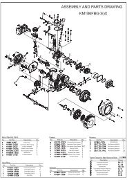
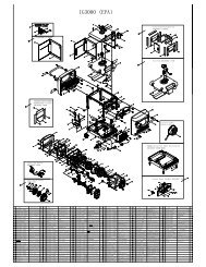
7. FRAME, HOUSING and FUEL TANK7.1 Disassembly and reassembly(IG6000)34
7.2 IG6000h handle assembly7.3 Vaporize control system35
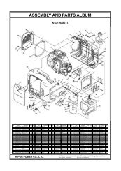
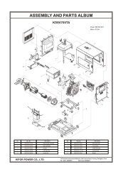
8. ALTERNATOR, IGNITION COIL, TRIGGER, FAN COVER8.1 Component Identificationa. Disassembly and assembly36
8.2 Ignition coil and triggera. Disassembly and reassembly触 发 头点 火 线 圈 TriggerIgnition点 火 线 圈 支 架Bracket for ignition coil coilb. Inspection(1) Ignition coil● Insert each meter pen between the primary coil plug-in of ignition coil to measure primary resistanceof ignition coil.Primary resistancevalue0.8~1.3Ω● Insert one ohmmeter lead to anyone primary coil plug-in of ignition coil and the other meter pen tospark plug cap to measure secondary resistance of the ignition coil.Secondary resistancevalue15~21KΩ37
(2) Trigger● Insert each meter pen to each trigger outgoing line to measure trigger resistance.Trigger headresistance80~130ΩC. AdjustmentAdjust the clearance between the trigger head and rotor.Trigger headclearance.020-.029 in. (0.50~0.75 mm)Insert the feeler gauge between the bulge on the trigger head and the rotor to measure clearance.Loosen the two bolts on the bracket to obtain the proper. When tightening, apply equal torque to bothmounting bolts to prevent “cocking” the trigger to one side. Recheck the clearance after the adjustmenthas been made.38
8.3 Alternatora. Disassembly and reassemblyFlywheel nut M8x1.5120-130N m)b. Inspection(1) Ignition coilResistance valueOrange-Yellow/greenGray-Orange0.22~0.24Ω0.15~0.17Ω(2) External charging coilMeasure the resistance between the two blue wiresResistance value0.03~0.04Ω(3) Built-in charging coilMeasure the resistance between the two purple wires.Resistance value0.12~0.16Ω(4) Sub winding coilMeasure the resistance between two white wires (or green depending on the date of manufacture).Resistance value0.08~0.12Ω(5) Main windingMeasure the resistance between three wires in black(or red).Resistance value120/240V 120V 240VDouble voltage Single voltage0.45~0.60Ω 0.09~0.10Ω 0.9~1.1Ω39
9. CYLINDER COVER and VALVE9.1 Disassembly and reassemblyb.40
9.2 Inspection● Valve spring lengthStandard(mm)Service limit(mm)39 37.5●Valve seat widthStandard(mm)Service limit(mm)0.8-1.2 2.0●Cylinder coverRemove all accumulated carbon in burning room and the washer remains on cylinder cover, and thencheck for crack of spark plug holes, valve base and valve conduct pipe.Check for distortion of cylinder cover with ruler and feeler gauge.Service limitIf exceed 0.1mm,please replace●External diameter of valve rodStandard (mm)Service limit (mm)Air intake 6.570~5.48 6.50Air outlet 6.55~6.57 6.5041
●Inner diameter of valve guiding pipeStandard (mm)Service limit (mm)Air intake/outlet 6.600-6.622 6.68●Clearance between valve rod and valve guiding pipeStandard (mm)Service limit (mm)Air intake 0.015~0.052 0.11Air outlet 0.030~0.072 0.1342
10. CRANKCASE COVER, CAMSHAFT, PISTON and CONNECTING ROD10.1 Disassembly and reassemblya. Crankcase coverb. Crankshaft, camshaft and piston43
●Alignment of time setting marksAlign camshaft with comparison marks of time setting gear (small gear on camshaft) before installing.c. Piston and connecting rod44
Assemble of piston ringCaution● Put the manufacturer mark facing up when installation;● Pay attention to the installation positions of 1 st and 2 nd ring.● Check if the piston ring can rotate freely after installing.● All openings of piston ring should be kept away from the direction of piston pin with 120 degree angle.10.2 InspectionInspection of low oil alarm(1)Lift the low oil alarm and measure the conductivity between lead wire and copper grounding pieceusing instrument.2)Convert the low oil alarm and measure again, it should be not conductive.3)Dip the low oil alarm into engine oil in order to inspect float, and measure again, it should be notconductive.●Noise and moving of shaftClean and dry the shaft, rotate the shaft manually and check the free gap; if any noise or moving, replacethe shaft.45
● Inner diameter of cylinderStandard (mm)Service limit (mm)88.015~88.035 88.17● External diameter of the apron of pistonStandard (mm)Service limit (mm)87.96-87.98 87.8510mm● Clearance between piston and cylinderStandard (mm)Service limit (mm)0.045~0.065 0.120● Side clearance of pistonStandard (mm)Service limit (mm)0.045~0.060 0.15046
● Terminal clearance of piston ringFix the piston ring in cylinder using the top part of piston and measure the terminal clearance of piston.Standard (mm)Service limit (mm)0.20~0.35 1.0● Height of piston ringStandard (mm)Service limit (mm)The first ring/thesecond ring1.97~1.99 1.87● External diameter of piston pinStandard (mm)Service limit (mm)19.994~20.000 19.95047
● Internal diameter of piston pin holeStandard (mm)Service limit (mm)20.002~20.008 20.050● Clearance between piston pin and pin holeStandard (mm)Service limit (mm)0.002~0.014 0.080● Internal diameter of the small terminal of connecting rodStandard (mm)Service limit (mm)20.007~20.020 20.090● Internal diameter of the large terminal of connecting rodStandard (mm)Service limit (mm)36.015~36.025 36.09048
● External diameter of crankshaft journalStandard (mm)Service limit (mm)25.960~35.975 35.900● Clearance of side face of big terminal of the connecting rodStandard (mm)Service limit (mm)1.05~1.25 1.5●Clearance of oil film of big terminal of connecting rod(1)Remove the engine oil on the surface of crankshaft journal.(2)Set plastic line gauge on the crankshaft journal, and install the connecting rod. Tighten the boltaccording to stipulate torque. Pay attention not to rotate the crankshaft when tightening.Tightening torque: 14~16N.m.(3)Remove the connecting rod and measure the thickness of plastic line gauge.(4)If clearance exceeds <strong>service</strong> limit, please replace the connecting rod, and then measure theclearance again. If the clearance still exceeds <strong>service</strong> limit after changing a new rod, please polish thecrankshaft journal and use the connecting rod that is less than standard value.Standard (mm)Service limit (mm)0.046~0.060 0.12049
● Height of camshaftStandard (mm)Service limit (mm)Air intake 32.60~32.80 32.25Air outlet 32.09~32.29 31.75●External diameter of camshaftStandard (mm)Service limit (mm)15.966~15.98 15.92●Inner diameter of bearing of camshaftStandard (mm)Service limit (mm)16.000~16.018 16.05050