Owner's Manual - Kipor Power Systems
Owner's Manual - Kipor Power Systems
Owner's Manual - Kipor Power Systems

You also want an ePaper? Increase the reach of your titles
YUMPU automatically turns print PDFs into web optimized ePapers that Google loves.
PREFACEThank you for purchasing a <strong>Kipor</strong> Generator.This manual covers the operation and preventive maintenance of the IG6000 andIG6000H generator with EPA and California Air Resources Board (CARB) certification if sodesignated.All information in this publication is based on the latest product information available at thetime of printing.We reserve the right to make changes at any time without notice and without incurring anyobligation.No part of this publication may be reproduced without written permission.This manual should be considered a permanent part of the generator and should remainwith it if it is resold.Pay special attention to statements preceded by the following words:Failure to properly follow these precautions can result in propertydamage, serious injury or DEATH!Read all labels and the owner's manual before operating this generator.Generators produce carbon monoxide, a poisonous, colorless, odorless gas that cancause death or serious injury.Indoor use of a generator can kill quickly. Generators should be used outdoors only.Generators should be used outdoors only and away from garages and open windows andprotected from rain and snow.
Always stop engine before refueling. Wait 5 minutes before restarting.Keep any source of ignition away from the fuel tank at all times.The portable generator is not meant to be used as a permanent back-up power system forthe home. A permanently installed stationary generator is designed to be safely used forthis specific purpose.Indicates a strong possibility of severe personal injury or death ifinstructions are not followed.Indicates a possibility of personal injury or equipment damage ifinstructions are not followed.NOTE Gives helpful information.If a problem should arise, or if you haveauthorized dealer or service center.any questions about the generator, consult anOur generators are designed to give safe and dependable service ifoperated according to the instructions. Read and understand the<strong>Owner's</strong> <strong>Manual</strong> before operating the generator. Failure to do socould result in personal injury or equipment damage.- 2 -
CONTENTSPREFACE ...................................................................................................................................... 1CONTENTS ................................................................................................................................... 31. SAFETY INSTRUCTIONS ......................................................................................................... 52. COMPONENT LOCATIONS ...................................................................................................... 82.1 Exterior View ........................................................................................................................ 82.2 Inlet System .......................................................................................................................... 92.3 Exhaust System .................................................................................................................... 92.4 CARB Evaporative Control System .................................................................................... 102.5 Carbon Canister .................................................................................................................. 112.6 Control Panel ...................................................................................................................... 122.7 Serial Number ..................................................................................................................... 123. PRE OPERATION CHECK ...................................................................................................... 133.1 Engine Oil Level ................................................................................................................. 133.2 Fuel Level ........................................................................................................................... 143.3 Air Cleaner .......................................................................................................................... 154. STARTING THE GENERATOR .............................................................................................. 165. GENERATOR USE ................................................................................................................. 195.1 AC <strong>Power</strong> Application ......................................................................................................... 215.2 Output and Overload Indicators .......................................................................................... 225.3 Voltage Selection Switch .................................................................................................... 235.4 Smart Throttle ..................................................................................................................... 245.5 Air Conditioning Operation .................................................................................................. 245.6 DC <strong>Power</strong> Application ......................................................................................................... 256. STOPPING THE GENERATOR ............................................................................................. 277. MAINTENANCE ..................................................................................................................... 287.1 Emission Control System ................................................................................................... 287.2 Maintenance Schedule ....................................................................................................... 317.3 Changing The Oil ................................................................................................................ 317.4 Air Cleaner Service ............................................................................................................. 327.5 Spark Plug Service ............................................................................................................. 337.6 Spark Arrestor Maintenance .............................................................................................. 35- 3 -
8. TRANSPORTING/STORAGE ................................................................................................. 369. TROUBLESHOOTING ........................................................................................................... 3710. SPECIFICATIONS ................................................................................................................ 3911. WIRING DIAGRAM ................................................................................................................ 4012. WHEEL KIT .......................................................................................................................... 4112.1 IG6000 ............................................................................................................................ 4112.2 IG6000H ......................................................................................................................... 42- 4 -
1. SAFETY INSTRUCTIONS■ Our generators are designed to give safe anddependable service if operated according to theseinstructions.Read and understand the owner's manual beforeoperating the generator. Failure to do so could result inpersonal injury or equipment damage.■Exhaust gas contains poisonous carbon monoxide.Never run the generator in an enclosed area.Be sure to provide adequate ventilation.The muffler becomes very hot during operation andremains hot for several minutes after stopping theengine.Be careful not to touch the muffler while it is hot.Let the engine cool before storing the generator indoors.The engine exhaust system will be heated duringoperation and remain hot immediately after stopping theengine.To prevent burns, pay attention to the warning marksattached to the generator.The generator must be operated outside withadequate ventilation.It cannot be operated in an enclosed compartment of anyvehicle or garage area.- 5 -
To ensure safe operation:■Gasoline is extremely flammable and explosive undercertain conditions. Refuel in a well ventilated area withthe engine stopped.■Keep away from smoking materials, sparks and othersources of combustion when refueling the generator.Always refuel in a well-ventilated location.■Wipe up spilled gasoline at once.■Restrict use of the generator in high-hazard risk areas.■Connections for standby power to a building's electricalsystem must be made by a qualified electrician and mustcomply with all applicable laws and electrical codes.Improper connections can allow electrical current fromthe generator to back feed into the utility lines. Suchback feed may electrocute utility company workers orothers who contact the lines during a power outage, andwhen utility power is restored, the generator mayexplode, burn, or cause fires in the building's electricalsystem. This generator is not designed to be connectedto an automatic transfer switch. Serious damage to theengine and inverter module may result.■ Always make a pre-operation inspection before youstart the engine.■Place the generator at least three feet or one meter awayfrom buildings or other equipment during operation.■Operate the generator on a level surface to prevent fuelspillage or oil starvation.■Know how to stop the generator quickly and understandoperation of all the controls. Never permit anyone tooperate the generator without proper instructions. Keepchildren and pets away from the generator when it is inoperation.- 6 -
■Never operate the generator with the door open or anypanels removed. Do not operate in any enclosure suchas an RV compartment.■Keep away from rotating parts while the generator isrunning.■The generator is a potential source of electrical shockswhen misused; do not operate with wet hands.■Do not operate the generator in rain or snow or let it getwet.- 7 -
2. COMPONENT LOCATIONS2.1 Exterior View火 花 塞
2.4 CARB Evaporative Control SystemFuel tank cover油 箱 盖Threaded sleeve油 箱 盖 内 螺 纹 套Cotter 开 口 pin 销油 Pallet 箱 盖 内 棘 爪Bushing油 箱 盖 内 称 套垫 Washer 圈油 Gasket 箱 盖 内 垫 片油 箱 Fuel 盖 总 cap 成Filter 加 油 口 screen 过 滤 网防 掉 Hook 倒 钩Fuel tank油 箱Certificate No.材 X6800BM 料 和 证 书 编 号X6800BMQ-08-006Q-08-006Certificate 证 书 编 号 No.C-U-07-016C-U-07-016bracket碳 罐 固 定 皮 带Carbon canister 碳 罐 (650cc) (650cc)Curved 大 气 hose 弯 管Fuel 输 hose 油 管油 Fuel 开 关 switch 组 件螺 钉ScrewCertificate 证 书 编 号 No.C-U-05-012碳 罐 Fixed 固 定 frame 架 焊 合Bolt 螺 栓碳 罐 负 压 管Connected to air filter( 接 空 滤 )Vent 油 箱 hose 通 气 管- 10 -
2.5 Carbon Canister Location (CARB only)碳 罐 固 Bracket 定 皮 带Curved 大 气 hose 弯 管Carbon 碳 罐Canister碳 罐 负 压 管油 箱 通 气 管Vent hose- 11 -
2.6 Control PanelGFCI ReceptacleChoke Handle120V 30A Receptacle120/240V 30A ReceptacleDC Receptacle2.6 Control panelSmart ThrottleIndicatorGFCI Receptacle交 流 插 座Choke 阻 风 Handle 门 手 柄120V 交 流 30A 插 座 Receptacle交 120/240V 流 插 座 30A ReceptacleDC Receptacle直 流 插 座Smart 智 能 Throttle 节 气 门指 示 灯IndicatorEngine发 动Switch机 开 关接 Ground 地 端 Terminal过 Overload 载 保 护 器 Reset Switch电 压 选 Voltage 择 开 关 Selection SwitchFuel 燃 油 Switch 开 关2.7 Serial NumberThe engine serial number is stamped on the engine block to the left of the oil drain plug. Inmost cases the battery will have to be removed to view it clearly. Refer to this numberwhen ordering parts or making technical inquiries.- 12 -
3. PRE-OPERATION CHECKBe sure to check the generator on a level surface with the engine stopped.3.1 Check the engine oil levelWARNING■ Using non detergent or 2-stroke eng ine oil could shorten the engine's service life.■ Use a high-detergent, premium quality four cycle engine oil, certified to meet or exceedU.S. Automobile manufacturer's requirements for API Service Classification SG/SF.■ Select the appropriate viscosity for the average temperature in your area.SAE Viscosity GradesAmbient TemperatureOpen the service door. Remove the oil filler cap and wipe the dipstick with a clean rag.Check the oil level by inserting the dipstick in the filler hole without screwing it in. If the oillevel is below the end of the dipstick, refill with recommended oil up to the top of the oilfiller neck.Upper limitLower limitDipstickOil drain bolt- 13 -
CAUTION■Running the engine with insufficient oil can cause serious engine damage.■The oil Alert System will automatically stop the engine before the oil level falls below thesafe limit. However, to avoid the inconvenience of an unexpected shutdown, it is stilladvisable to visually inspect the oil level before each use.3.2 Check the fuel levelUse unleaded 87 octane regular gasoline Do not use premium or high octane fuels.The engine is tuned to run on regular gasoline and engine damage and poor performancemay result from using higher octane fuels.If the fuel level is low, refill to the shoulder of the fuel strainer.Never use an oil/gasoline mixture or dirty gasoline.Avoid getting dirt, dust or water in the fuel tank.After refueling, tighten the fuel filler cap securely.WARNING■Gasoline is extremely flammable and is explosive under certain conditions.■Refuel in a well-ventilated area with the engine stopped. Do not smoke or allow flame orsparks in the area where the engine is refueled or where gasoline is stored.■Do not overfill the fuel tank (there should be no fuel in the filler neck). After refueling,make sure the fuel filler cap is closed properly and securely.■Be careful not to spill fuel when refueling. Spilled fuel or fuel vapor may ignite. If any fuelis spilled, make sure the area is dry before starting the engine.■Avoid repeated or prolonged contact with skin or breathing of vapors. KEEP OUT OFREACH OF CHILDREN.Fuel tank capacity: 5.8 gallons or 22 litersFuel filler capLoosenTightenFuel surfaceStrainer- 14 -
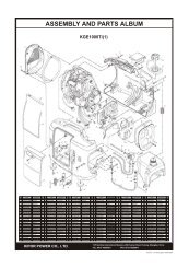
GASOLINES CONTAINING ALTERNATE FUELSIf you decide to use a gasoline containing ethanol be sure its octane rating isno lower than the specification. Do not use a blend that contains more than10% ethanol. Do not use gasoline containing methanol.3.3 Check the air cleanerCheck the air cleaner elements to be sure they are clean and in goodcondition.Open the service cover. Remove the air cleaner cover and remove the paperair cleaner element. Replace the element if dirty or damaged.Air cleaner baseAir cleaner elementAir cleaner coverAir Cleaner AssemblyCAUTION■Never run the engine without the air cleaner. Rapid engine wear will result fromcontaminants such as dust and dirt, being drawn through the carburetor, into the engine.- 15 -
4. STARTING THE GENERATORCAUTION■ When starting the generator after adding fuel for the first time, afterlong-term storage, or after running out of fuel, turn the fuel valve lever to the"ON" position then wait 10 to 20 seconds before starting the engine.a. Turn the fuel valve lever to the ON position.Fuel 燃 油 Switch 开 关Fig. 7b. Pull the choke knob out to the CLOSED positionDo not use the choke when the engine is warm or the air temperature is high,Choke Knob阻 风 门 开 关- 16 -
c. Insert the engine key and turn the ignition switch to ON position.OFF关开ON开 START 始Ignition 发 动 机 switch 开 关图 9 起 动 旋 钮 工 作 位 置 图d. Turn the ignition switch to the START until the engine starts.OFF关开 ON开 START 始发 Engine 动 机 开 switch 关- 17 -
4.5 Push the choke knob to the OPEN position as the engine warms upChoke Knob阻 风 门 开 关High altitude operationAt high altitude, the standard carburetor air-fuel mixture will be excessively richPerformance will decrease, and fuel consumption will increase.High altitude performance can be improved by installing a smaller diametermain fuel jet in the carburetor.. If you operate the generator at altitudes higherthan 5,000 feet (1,500m) above sea level, have your authorized dealer performthe jet replacement..Even with suitable carburetor jetting, engine horsepower will decreaseapproximately 3.5% for each 1000 feet (350m) increase in altitude. The effectof altitude on the horsepower will be greater than this if no carburetormodification is made.CAUTION■Operation of the generator at an altitude lower than the carburetor is jettedfor may result in reduced performance, overheating, and serious enginedamage caused by an excessively lean air/fuel mixture.- 18 -
5. GENERATOR USEWARNING■To prevent electrical shock from faulty appliances, the generator should begrounded. Connect a length of heavy wire between the generator's groundterminal and an external ground source.Ground Terminal接 地 端CAUTION■ Limit operation requiring maximum power to 30 minutes. For continuousoperation do not exceed the rated power. In either case, the total wattage of allappliances connected must be considered.■ Do not exceed the current limit specified for any one receptacle.■ Do not connect the generator to a household circuit. This could cause thedamage to the generator or to electrical appliances in the house.■ Do not modify or use the generator for other purposes than which it isintended. Also observe the following when using the generator:·Do not connect generators in parallel.·Do not connect an extension to the exhaust pipe.■ When an extension cable is required, be sure to use tough rubber sheathedflexible cable.■ Keep the generator away from other electric cables or wires such ascommercial power supply lines.- 19 -
NOTE■You may use DC receptacle when using AC supply.■If you want to use AC and DC receptacle simultaneously, the total outputshould not be over the sum output of AC and DC.■Electrical equipment containing the wiring and plug should not have defect.Control panelGFCI Receptacle交 流 插 座Choke 阻 风 Handle 门 手 柄120V 交 流 30A 插 座 Receptacle交 120/240V 流 插 座 30A ReceptacleDC Receptacle直 流 插 座Smart 智 能 Throttle 节 气 门指 示 灯IndicatorEngine发 动Switch机 开 关接 Ground 地 端 Terminal过 Overload 载 保 护 器 Reset Switch电 压 选 Voltage 择 开 关 Selection SwitchFuel 燃 油 Switch 开 关- 20 -
5.1 AC Application1. Start the engine and make sure the green output indicator light comes on.2. Confirm that the appliance to be used is switched off and plug in theappliance.CAUTION■ Be sure that all appliances are in good working order before connectingthem to the generator. If an appliance begins to operate abnormally,becomes sluggish, or stops suddenly, turn off the generator engine switchimmediately. Disconnect the appliance and examine it for signs ofmalfunction.- 21 -
5.2 Output and Overload IndicatorsThe green output indicator light will remain ON during normal operatingconditions. If the generator is overloaded or if there is a short in the connectedappliance the output indicator will go OFF and the overload indicator will goON and current to the connected appliance will be shut off. Correct theoverload condition and press the overload reset switch on the panel to restoreAC power.Check the engine oil level if the red low oil indicator comes ON.NOTICE■Before connecting an appliance to the generator, check that it is in goodorder and that its electrical rating does not exceed that of the generator.Then connect the power cord of the appliance and start the engine.NOTICE■When an electric motor is started, both the overload indicator light and theoutput indicator light may go on simultaneously. This is normal if the overloadindicator light goes off after about four seconds. If the overload indicator lightstays on, consult your dealer.- 22 -
.The two 120V receptacles are rated at 20 and 30 amps respectively.Shouldthis current be exceeded, the circuit protection device willactivate and cutallcurrent to the receptacle. This will be indicated by the push button poppingout. Reduce the load to the receptacle and reset the circuit protector bypushing in the button.5.3 Voltage Selection SwitchThe voltage selection switch has two positions: AC120V and AC120/240V.1. When the voltage selection switch is in the 120/240V position, the generatorsupplies both 120V and 240V AC power. If you operate the generator with theswitch in this position, the electric current is limited to 15 amps to the 120Vreceptacles although it can provide 15 amps at 240V from the 120/240Vreceptacle.2. When the voltage selection switch in the 120V position, the generatorsupplies 120V AC only. It can supply a full 30 amps to the 30 Amp receptacleor 20A to the GFCI receptacle. Total current is limited to 45.8 amps at ratedload.- 23 -
5.4 Smart ThrottleWhen the SMART throttle is placed in the on position, engine speed is kept atidle automatically when the electrical load is disconnected and returns to theproper speed required by the electrical load when the load is reconnected. Theengine speed varies according to the amount of load applied to the generator.Placing the smart throttle in the on position is recommended to minimize fuelconsumption and engine noise while in operation.■When high electrical load appliances areconnected simultaneously, turn the SMARTthrottle switch to the OFF position to reducevoltage fluctuation.■The SMART throttle system does not operateefficiently if the electrical appliance will be used ina rapid on-off or low to high rpm mode.When the smart throttle is in the off position, the engine runs at rated loadRPM.5.5 Air Conditioning OperationFor best results, the SMART throttle switch should be in the off position. Bringthe generator to a normal operating temperature before applying the airconditioning load. Always allow a 2 minute wait period when manually cyclingan air conditioner off and on. A longer wait period may be required underunusually hot weather conditions. Additionally, all other loads should be turnedoff until the air conditioner has started and is performing normally. It is alsoimportant to follow the air conditioner manufacturer's instructions for startingandrestarting for proper operation. Some air conditioner manufacturers offer- 24 -
a start capacitor as an extra cost option. The lack of a start capacitor cancause the air conditioner to draw too high a starting current and overload thegenerator. Contact your air conditioner dealer if you consistently haveproblems starting your air conditioner with the generator.5.6 DC <strong>Power</strong> ApplicationThe DC receptacle may be used for charging 12 volt automotive-type batteriesonly. It is not designed to operate DC motors. Output voltage is 15-30V. DCoutput will vary according to the position of the Smart throttle switch.a. Connect the charging cable to the DC receptacle of the generator and thento the battery terminals.■To prevent the possibility of creating sparks near thebattery, connect the charging cable first to the generatorthen to the battery. Disconnect the cable first at thebattery.■Before connecting the charging cable to a battery that isinstalled in a vehicle, disconnect the vehicle's batteryground cable. Reconnect the vehicle's ground cable afterthe charging cables are removed. This procedure willprevent the possibility of a short circuit and sparks ifaccidental contact is made between a battery terminaland the vehicle's frame or body.■Do not attempt to start an automobile engine with thegenerator still connected to battery. The generator maybe damaged.■Connect the positive battery terminal to the positivecharging cord. Do not reverse the charging cables orserious damage to the generator and/or battery mayoccur.- 25 -
■The battery gives off explosive gases: keep sparks,flames and cigarettes away. Provide adequate ventilationwhen charging.■The battery contains sulfuric acid (electrolyte). Contactwith skin or eyes may cause severe burns. Wearprotective clothing and a face shield.A. If electrolyte gets on your skin, flush with water.B. If electrolytes gets in your eyes, flush with water forat least 15 minutes and call a physician.■ Electrolyte is poisonous.If swallowed, drink large quantities of water or milk andfollow with milk of magnesia or vegetable oil and call aphysician.■ Keep out of reach of children.The DC output is to be used to charge batteries only.Serious damage to the stator windings can occur ifconnected to a DC motor or transformer.b. Start the generator.■ The DC receptacle may be used while the AC power is in use.■ The DC receptacle is protected from an overload with a fuse. If the DC circuitis overloaded, the 5 amp fuse will blow and power to the DC receptacle willcease. The red light on the DC panel will illuminate. The fuse is located to theleft of the receptacle and is accessed by snapping open the access door.Replace the fuse with one of the same capacity. Using a higher rated fuse maycause damage to the generator alternator.保 5 险 amp 丝 fuse打 开直 流 插 座Access door- 26 -
6. STOPPING THE GENERATORTo stop the engine in an emergency, turn the engine switch OFF.In normal use:1. Switch off the connected equipment and pull the plug from the receptacle.2. Turn off the ignition switch.3. Turn the fuel valve lever to the OFF position.- 27 -
7. MAINTENANCEThe purpose of the maintenance and adjustment schedule is to keep thegenerator in the best operating condition.■Shut off the engine before performing anymaintenance. If the engine must be run, makesure the area is well ventilated. The exhaustcontains poisonous carbon monoxide gas.■Use genuine <strong>Kipor</strong>parts or the equivalent. Theuse of replacement parts which are not ofequivalent quality may damage the generator.7.1 Emission Control SystemEmission sourceExhaust gas contains carbon monoxide, nitrous oxide (NOx), andhydrocarbons. It is very important to control the emissions of NO X andhydrocarbons as they are a major contributor to air pollution. Carbon monoxideis a poisonous gas. The emission of fuel vapors is a source of pollution as well.The <strong>Kipor</strong> generator engine utilizes a precise air-fuel ratio and emission controlsystem to reduce the emissions of carbon monoxide, NO X , hydrocarbons, andevaporative fuel emissions.RegulationYour engine has been designed to meet current Environmental ProtectionAgency (EPA) and the California Air Resources Board (CARB) clean airstandards. The regulations dictate that the manufacturer provide operation andmaintenance standards regarding the emission control system. Tune upspecifications are provided in the Specifications section and a description ofthe emission control system may be found in the appendix to this manual,Adherence to the following instructions will ensure your engine meets theemission control standards.- 28 -
ModificationModification of the emission control system may lead to increased emissions.Modification is defined as the following:• Disassembling or modifying the function or parts of the intake, fuelor exhaust system.• Modifying or destroying the speed governing function of thegenerator.Engine faults that may affect emissionAny of the following faults must be repaired immediately. Consult with yourauthorized <strong>Kipor</strong> service center for diagnosis and repair:• Hard starting or shut down after starting• Unstable idle speed• Shut down or backfire after applying an electrical load• Backfire or afterfire.• Black smoke and/or excessive fuel consumptionReplacement parts and accessoriesThe parts making up the emission control system applied to <strong>Kipor</strong> engine havebeen specifically approved and certified by the regulatory agencies. You cantrust the replacement parts supplied by <strong>Kipor</strong> have been manufactured to thesame production standard as the original parts. The use of replacement partsor accessories which are not designed by <strong>Kipor</strong> may affect the engineemission performance. The manufacturers of replacement parts andaccessories have the responsibility to guarantee that their replacementproducts will not adversely affect emission performance.MaintenanceMaintain the generator according to the maintenance schedule in this section.Service items more frequently when used in dusty areas, or under conditionsof high load, temperature, and humidity.- 29 -
Air Quality Index (only for California certified models)CARB requires that an air quality index label be attached to every certifiedengine showing the engine emission information for the emission durationperiod. The label is provided for the user to compare the emissionperformance of different engines. The lower the air index, the better the engineemission performance. The description of durability is helpful for the user tolearn the engine emission duration period and the service life of emissioncontrol system. Refer to the warranty section of this owner’s manual for moreinformation..- 30 -
7.2 Maintenance ScheduleNOTE: (1) Log hours of operation to determine proper maintenance.(2) Service more frequently when used in dusty areas.(3) These items should be serviced by an authorized dealer unlessthe owner has the proper tools and is mechanically proficient. See theservice manual.7.3 Changing OilDrain the oil while the engine is still warm.DipstickUpper 上 限 位 limitOil drain bolt下 限 位Lower limit- 31 -
1. Open the left side maintenance cover.2. Take out the oil outlet plug.3. Remove the drain bolt, and drain the oil. Retighten the bolt securely.4. Refill with the recommended oil and check the level.5. Close the left side maintenance cover.Engine oil capacity: 1.1LNOTE■ Please dispose of used motor oil in a manner that is compatible with theenvironment. We suggest you take it in a sealed container to your local servicestation for reclamation. Do not throw it in the trash or pour it on the ground.7.4 Air Cleaner ServiceA dirty air cleaner will restrict air flow to the carburetor to prevent carburetormalfunction, service the air cleaner regularly. Service more frequently whenoperating the generator in extremely dusty areas.WARNING■ Do not use gasoline or low flash point solvents for cleaning. They areflammable and explosive under certain conditions.CAUTION■Never run the generator without the air cleaner. Rapid engine wear mayresult1. Open the left side maintenance cover.2. Unsnap the clips, remove the air cleaner cover.3. Inspect the air cleaner. Replace if dirty or the replacement is called forbased on hours of operation.4. Reinstall the air cleaner cover.5. Close and latch the left side maintenance cover.- 32 -
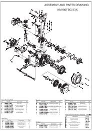
.7.5 Spark Plug ServiceRecommended spark plug: WR7DCTo ensure proper engine operation, the spark plug must be properly gappedand free of deposits.1. Open the left side maintenance cover.2. Remove the spark plug cap.Spark plug wrenchFig, 15Spark plug3. Clean dirt from around the spark plug base.4. Use the wrench to remove the spark plug.5. Visually inspect the spark plug. Discard it if the insulator is cracked orchippedClean the spark plug with a wire brush if it is to be reused.6. Measure the plug gap with a feeler gauge.The gap should be 0.7-0.8mm (0.028-0.031in). Correct as necessary bycarefully bending the side electrode.- 33 -
Spark plug clearance 火 花 塞 间 隙0.7-0.8CAUTION■ The spark plug must be securely tightened. An improperly tightened plugcan become very hot and possibly damage the generator.■ Never use a spark plug with an improper heat range.7. Install the spark plug carefully, by hand, to avoid cross-threading.8. After a new spark plug has been seated by hand, it should be tightened 1/2turn with a wrench to compress its washer.If a used plug is being reinstalled, it should only require 1/8 to 1/4 turn afterbeing seated.9. Reinstall the spark plug inspection cover and tighten the cover screw.10. Close and latch theleft side maintenance cover.- 34 -
7.6 Spark Arrestor MaintenanceRear 后 面 cover 罩Secondary gulp valve二 次 补 气 阀Spark 火 星 捕 arrester 捉 器Fig, 17WARNING■ If the generator has been running, the muffler will be very hot. Allow it tocool before proceeding.CAUTION■ The spark arrester must be serviced every 100 hours to maintain itsefficiency.1. Remove the back cover.2. Remove the exhaust tail pipe and spark arrester.3. Use a brush to remove carbon deposits from the spark arrester screen.NOTE■ Inspect the spark arrester screen for holes or tears. Replace if necessary.4. Reinstall the spark arrester.5. Reinstall the upper muffler protector.- 35 -
8. TRANSPORTING/STORAGEa. When transporting the generator, turn the fuel valve lever OFF and keep thegenerator level to prevent fuel spillage. Fuel vapor or spilled fuel may ignite.Do not transport the generator in a vehicle with fuel in the tank.b. Exercising the generatorIt is essential that the generator be exercised on a regular basis. This willprevent the accumulation of varnish or sludge in the fuel system and alsoremove moisture from the generator windings. Additionally, seals and othermoving engine parts are kept lubricated and the battery is recharged.Exercise the generator by running it with at least a 1/2 load (1500W) for 60minutes per month. Gasoline fuel treatments to prevent contamination of yourfuel supply are available from your dealer. Fuel varnishing necessitatingreplacement of the carburetor is not a warrantable failure.c. Before storing the unit for an extended period:1. Ensure the storage area is free of excessive humidity and dust.2. Drain the fuelA. Open the left side maintenance cover.B. Turn fuel valve lever to ON and then loosen the carburetor drain screw.Drain the gasoline from the carburetor and fuel tank into a suitable container.Drain plugFig.19 Drain the fuel3. Once a month, recharge the battery.4. Change the engine oil.5. Remove the spark plug and pour one tablespoon of clean engine oil into thecylinder. Crank the engine several revolutions to distribute the oil and thenreinstall the spark plug.- 36 -
9. TROUBLESHOOTINGWhen the engine will not start:Is there fuel in the tank?YESIs the engine switch on?YESIs the fuel valve on?YESIs there enough oil in the engine?NONONONORefill the fuel tank.Turn the engine switch on.Turn the fuel valve on.Add the recommended oil.YESIs there a spark fromthe spark plug?NOReplace thespark plugStill no sparkTake the generator toan authorized KIPORservice center..■ Be sure there is no spilledfuel around the spark plug. Spilledfuel may ignite.Is the fuel reaching the carburetor?If the engine still does not start, takethe generator to an authorized <strong>Kipor</strong>service center.To check:1) Remove the spark plug cap and clean anydirt from around the spark plug.2) Remove the spark plug and install the sparkplug in the plug cap.3) Set the plug side electrode on the cylinderhead to ground.4) Crank the engine; sparks should jump acrossthe gap.To check:1) Turn off the fuel valve and loosen the drainscrew.2) Fuel should flow from the drain when the fuelvalve is turned on.- 37 -
AC appliance does not operate:Is the output indicator light ON?YESNOIs the overlo ad indicatorlight ON?NOTake the generator to a <strong>Kipor</strong>service center.YESCheck the electrical appliance or NOTake the generator to anequipment for any defects. authorized KIPOR service center.YES■ Replace the electricalappliance or equipment.■Take the electrical applianceor equipment to an electricalshop for repair.No output at the DC receptacle:Is the fuse blown?YESReplace the fuse.NOTake the generator to anauthorized KIPOR servicecenter.- 38 -
10. SPECIFICATIONSGENERATORModelIG6000/IG6000hRated frequency (Hz)60Rated voltage (V) 120/240Rated current (A) 45.8/22.9Rated output (Watts) 5500Max output (Watts) 6000DC voltagePhaseENGINEModel KG390GTi12V@5.0ASingleType Single cylinder, 4 stroke, vertical, air-cooled, OHV,Displacement (Boregasoline engine× Stroke)23.7 cu. In. (389 cc)Compression ration8.5:1Rate d power [kW(hp)/(r/min))] 7.7/3600Rated rotation speed (rpm) 3600Ignition systemT. C. ISpark plugWR7DCStarting systemElectric starter/manual recoilFuelAutomotive unleaded gasoline, 87 octaneLube oil SAE 10W30 (above CC grade)Lube oil capacity1.2 qt. (1.1L)GENERALFuel tank capacity (L)5.8gal.(22L)Continuous running time at rated 7.5 HoursoutputNoise level(zero load~ full load) @ 23' 64-65 decibels(7M)Overall dimension (L×W×H) in. (mm) IG6000: 31.6×19.5×24.6 (802×495×624)IG6000h: 48.6× 25.59×30.3 (1235×650×770)Dry weight –lbs (kg)IG6000:(209 (95)IG6000h: 263 (115)Tune Up SpecificationsSpark Plug GapValve Clearance- cold (Intake)Valve Clearance- cold (Exhaust)0.024-0.028 in (0.6-0.7 mm)0.0039 ±.0008 in (0.10 ± 0.02 mm)0.0059 ± .0008 in (0.10 ± 0.02 mm)- 39 -
11. WIRING DIAGRAM
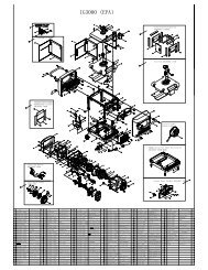
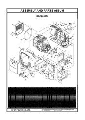
12. WHEEL KIT12.1 IG60001234 51. Washer4. Wheel3. Lock pin4. Locking swivel wheel5. Bolt M6X16To install the front wheels, install a washer on the axle, then the wheel, anotherwasher and secure with a wheel clip.To install the locking swivel wheels, line up the bolt holes in the chassis withthe holes in the wheel attaching plate. Secure with the 4 bolts.- 41 -
12.2 IG6000H15 24 37 61. IG6000H Chassis- installed 5. 10” Wheel2. Support Bracket- (4) 6. Wheel Washer (4)3. Front Stabilizer (2) 7. Wheel Clip4. Axle AssemblyAssembly:1. Install the four support brackets and secure with bolts.2. Attach the front stabilizers to the chassis (below the handles)3. Attach the axle assembly.4. Install one washer on the axle against each welded stop.5. Install the two wheels.6. Install the two remaining washers and secure with the wheel clips.The handles are preassembled before packaging. To raise the handles, simply raise thehandle assembly to a horizontal position. To retract the handles, slide the chrome collarstoward you to clear the sleeve and lower them to the starting position.- 42 -