Shark -new motor design concept for energy saving- applied to - VBN
Shark -new motor design concept for energy saving- applied to - VBN
Shark -new motor design concept for energy saving- applied to - VBN

You also want an ePaper? Increase the reach of your titles
YUMPU automatically turns print PDFs into web optimized ePapers that Google loves.
34<br />
Chapter 2 Linear analysis of the <strong>Shark</strong> switched Reluctance Mo<strong>to</strong>r<br />
generalization of the saw-<strong>to</strong>othed and square wave <strong>Shark</strong> SRMs. As the dimension l <strong>to</strong>p , shown in<br />
Fig.2.7, varies, the inductance gain assumes values varying between those of the saw-<strong>to</strong>othed and<br />
square wave <strong>Shark</strong> SRMs. The inductance gain of the elliptical profile exceeds that of the saw<strong>to</strong>othed<br />
profile but it is smaller than that of the square wave profile.<br />
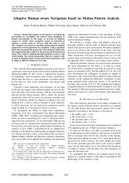
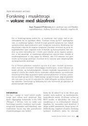
In Fig.2.19, the curves showing the inductance ratio variation with angle β are presented <strong>for</strong> the<br />
saw-<strong>to</strong>othed, square wave, elliptical and trapezoidal <strong>Shark</strong> profiles. A similar variation is observed<br />
<strong>for</strong> the <strong>energy</strong> ratio, presented in Fig.2.20<br />
These curves show that:<br />
• the influence of the <strong>Shark</strong> profile on the per<strong>for</strong>mances of the magnetic circuit increases with<br />
the angle β<br />
• the saw <strong>to</strong>othed and the square waved profiles represents respectively the lower and the<br />
upper limits <strong>for</strong> the inductance and <strong>energy</strong> gain<br />
• the trapezoidal profile may be considered <strong>to</strong> be a generalisation of both the saw-<strong>to</strong>othed and<br />
the square wave profiles.<br />
Table 2. 1 Inductance gain <strong>for</strong> saw-<strong>to</strong>othed, square-wave, ellipsoidal and trapezoidal <strong>Shark</strong> profiles<br />
Profile type Inductance gain in the aligned position in terms Inductance gain at<br />
of<br />
=45 [deg]<br />
Saw-<strong>to</strong>othed profile<br />
1<br />
k saw =<br />
cos β<br />
1.41<br />
Square wave profile k square = ( 1+ tan β )<br />
2<br />
Ellipse profile<br />
π<br />
kellipse<br />
= ⋅ ( 1+<br />
tan β ) ⋅<br />
4<br />
3 − 4 −<br />
2<br />
1−<br />
tan β<br />
1+<br />
tan β<br />
1.57<br />
Trapezoidal profile<br />
( ) ( ) 2<br />
2<br />
ktrap = 2 ⋅ +<br />
1.41 (k=0)<br />
1−<br />
2 ⋅ kk<br />
+ tan β ,<br />
1.48 (k=0.1)<br />
l<strong>to</strong>p<br />
k = ;<br />
lshk<br />
k ≤ 0.<br />
5<br />
1.67 (k=0.3)<br />
2.00 (k=0.5)<br />
According <strong>to</strong> this idealised analysis (2.13), the number of <strong>Shark</strong> teeth in a given machine does not<br />
affect the per<strong>for</strong>mances of the <strong>Shark</strong> configuration if the ratio of the <strong>Shark</strong> <strong>to</strong>oth height <strong>to</strong> its length<br />
remains constant ( β =const.). This is contradicted by equation (2.18), which shows that if there are<br />
many <strong>Shark</strong> profiles much active area of the air gap is lost. This is due <strong>to</strong> the fact that the flux<br />
density is not uni<strong>for</strong>mly distributed along the <strong>Shark</strong> air gap. This subject will be discussed in<br />
chapter 3 as it may be decisive in choice of <strong>Shark</strong> profile <strong>for</strong> further considerations.