Bladerunner II Manual Candcnc
Bladerunner II Manual Candcnc
Bladerunner II Manual Candcnc

Create successful ePaper yourself
Turn your PDF publications into a flip-book with our unique Google optimized e-Paper software.
BladeRunner <strong>II</strong> <strong>Manual</strong><br />
CandCNC<br />
G251-4<br />
REV1<br />
All Content Copyrighted 2008-2009<br />
any reproduction in printed or electronic formats is prohibited<br />
without the express written permission of CandCNC<br />
CNC and motion control involves equipment that can cause serious injuries.<br />
CandCNC assumes no liability for ANY damages to any person or property<br />
from the proper or improper use of any equipment CandCNC sells or from any<br />
advice verbal or written. Use the equipment at your own risk. Practice good<br />
safety precautions. Be smarter than the machine.<br />
:<br />
ll
ON<br />
OFF<br />
AC<br />
POWER<br />
ON<br />
1<br />
0<br />
1<br />
0<br />
OFF<br />
AC<br />
POWER<br />
LED Pulse “Sniffer” shows actual<br />
Step & Dir pulses at the EZplug<br />
Card. LED’s light and flash with<br />
step. Color changes with<br />
direction<br />
PULSE MONITOR<br />
X Y Z A<br />
G251-4<br />
CandCNC<br />
DTHC SPS<br />
Multi-Axis Stepper Controller Dragon Expansion<br />
:<br />
ll<br />
PULSE MONITOR<br />
X Y Z A<br />
G251-4<br />
CandCNC<br />
DTHC SPS<br />
Multi-Axis Stepper Controller Dragon Expansion<br />
:<br />
ll<br />
STATUS LEDs<br />
Show processor activity on<br />
power-up (flashes). Shows<br />
Faults using flash “codes”<br />
LD shows Load Dump<br />
STATUS<br />
LD<br />
FAULT<br />
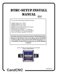
BLADERUNNER <strong>II</strong> FRONT PANEL FUNCTIONS<br />
MAIN POWER<br />
SWITCH<br />
Turns off power<br />
to Logic circuits.<br />
Shuts off MOTOR<br />
DC if ON<br />
TABLE I/O INPUT<br />
Port1 INPUT<br />
To PC<br />
DB25 Female Socket for cable<br />
interface to TABLE I/O Card.<br />
Has E-stop and all Inputs and<br />
external Outputs. Must be<br />
connected for operation<br />
STATUS<br />
LD<br />
FAULT<br />
TABLE I/O INPUT<br />
Port1 INPUT<br />
To PC<br />
DB25 Male Plug for cable<br />
interface to PC Parallel Port. All<br />
Step & Dir signals all logic level<br />
inputs and outputs to/from PC.<br />
Required for operation<br />
Confirms Power to<br />
EZPlug 251-4<br />
AUX<br />
POWER<br />
ON OFF<br />
MOTOR DC<br />
CP PWR SERIAL INPUT<br />
To PC<br />
Charge Pump<br />
ON<br />
Logic level<br />
Power<br />
ON<br />
CP PWR<br />
MOTOR DC POWER Turns<br />
ON/OFF AC power to<br />
48VDC power supply via<br />
rear DB9. Must be ON to<br />
come out of RESET in<br />
MACH<br />
AUX<br />
POWER<br />
ON OFF<br />
MOTOR DC<br />
SERIAL INPUT<br />
To PC<br />
DB9 cable to PC<br />
serial connector.<br />
Only needed for<br />
operation of<br />
Expansion Modules<br />
EXPANSION CARD<br />
To Remote Sensor<br />
Push<br />
Read<br />
TEST<br />
Expansion Card<br />
Test Varies with<br />
Card type.<br />
Recessed test<br />
button.<br />
EXPANSION CARD<br />
To Remote Sensor<br />
Push<br />
Read<br />
TEST
ON<br />
1<br />
0<br />
OFF<br />
AC<br />
POWER<br />
PULSE MONITOR<br />
X Y Z A<br />
G251-4<br />
CandCNC<br />
DTHC SPS<br />
Multi-Axis Stepper Controller Dragon Expansion<br />
FAULT LIGHT CODES<br />
:<br />
ll<br />
Flash<br />
Short<br />
Pause<br />
FAULT<br />
STATUS<br />
STOP<br />
LD<br />
STATUS<br />
LD<br />
FAULT<br />
TABLE I/O INPUT<br />
Long Pause<br />
Port1 INPUT<br />
To PC<br />
REPEAT<br />
REPEAT<br />
REPEAT<br />
AUX<br />
POWER<br />
ON OFF<br />
MOTOR DC<br />
CP PWR SERIAL INPUT<br />
To PC<br />
OVERVOLTAGE SHUTDOWN<br />
EXPANSION CARD<br />
To Remote Sensor<br />
Push<br />
Read<br />
TEST<br />
OVERLOAD (amps) SHUTDOWN<br />
OVERTEMP SHUTDOWN<br />
NORMAL INITIALIZE (power on)<br />
Continious Flash HIGH TEMP WARNING (proceeds shutdown)<br />
If you have a system shutdown you can use the FAULT LED and the Code Chart to help diagnose the source of the<br />
shutdown. The BladeRunner has an advanced internal micrprocessor that monitors the running conditions and will<br />
automatically shutdown and turn motor power off (provided DC power supply is controlled by the BladeRunner through<br />
the rear DB9 (To Power Commander). The processor circuit controls the logic shutdown and will indicate the cause<br />
based on the chart above. The circuit resets (code flash stops) when you push the ON button. If you see a constant<br />
flash it indicates an impending over temp shutdown. You should stop and turn off Motor DC and make sure the<br />
internal fan is running and there is no airflow blockage. In extremely harsh conditions dust. smoke and debris can get<br />
into the enclosure and impede airflow and cooling. Unplug the BladeRunner and open the case. Use a moderate (40<br />
PSI max) stream of air to clean out any debris.
The setup of the BladeRunner Series Interface involves the installation of MACH3<br />
software and some support files on the PC to be used for the machine controller.<br />
While we will guide you through the setup for MACH3 the MACH3 manual gives<br />
more in-depth instructions on each feature. Familiarize yourself with the controls<br />
on the BladeRunner Front Panel and with the loading and operation of MACH3<br />
with the proper profile. The initial part of this manual is devoted to getting MACH3<br />
properly installed with the right support files and profile to run the BladeRunner.<br />
After you have the software installed and the cables and satellite cards hooked up<br />
you will be guided through a series of tests to determine if everything is working.<br />
We ask that you go through the setup and manual in the order presented. If at<br />
some point you cannot get the expected results and check your connections and<br />
setup with no success, then call our tech support person (also the engineer,<br />
assembler, tester, webmaster and marketing guy!) at 903-364-2740. While we work<br />
a lot of strange hours we may not always be available to answer the call so leave a<br />
detailed message of the problem and how to get in touch with you will hear back<br />
from one of the staff. Often an email to Tom@CandCNC.com will get a response<br />
after hours or on weekends.<br />
Installation and setup of your MP3000.<br />
There are a series of steps you must complete to setup and interface the MP3000<br />
with your PC and Your Plasma torch<br />
� Install and setup the Primary parallel port in your PC<br />
� Setup and configure the first serial port (COM1) on your PC<br />
� Install MACH3 software (proper version)<br />
� Copy your MACH3 license into the MACH3 main folder<br />
� Run the install program from the CandCNC disk to load custom screens<br />
and setup files and Plug-ins<br />
� Open MACH3 and check screens and configure the PLUG-INs<br />
� Connect the 2 PC port cables (one 25Pin, one 9 Pin) to the front of the<br />
BladeRunner<br />
� Connect the Table I/O card to the Table I/O port on the front of the<br />
BladeRunner (see photos)<br />
� Run a quick series of tests to confirm the ports are working and that<br />
MACH3 is configured correctly<br />
� Do final checkout.<br />
� Setup and test any Expansion Cards (DTHC or Spindle Speed)<br />
� Fire up the machine and cut a test file.<br />
GENERAL SETUP
INSTALL and SETUP PRIMARY and/or SECONDARY PARALLEL PORTS<br />
NOTE: USE THIS SECTION ONLY IF YOUR PC DOES NOT HAVE A BUILT-IN<br />
PARALLEL PORT and/or SERIAL PORT OR YOU HAVE PURCHASED THE<br />
MPG101B HAND CONTROLLER THAT USES A SECOND PARALLEL PORT.<br />
Use the same procedure to install a primary (PORT1) Parallel Port (if your<br />
PC does not have one) or a second port. Do not attempt to use two<br />
separate parallel port cards of the same type to get two ports. For two<br />
ports use a Dual Parallel Port card. CandCNC stocks low cost parallel and<br />
parallel/serial PCI expansion cards.<br />
Make sure the card you install has drivers for the version of Windows you are<br />
running. Win2000 drivers may or may not work in XP (or visa versa). When you<br />
install the card in your computer and turn it back on, it should find the new<br />
hardware and when prompted, you should use the disk that comes with the port<br />
card to install the correct drivers. There should be instructions with the card on<br />
the proper way to install the drivers.<br />
After you install the parallel port and Windows recognizes the port(s) then open<br />
the device manager from the Hardware section under Windows /Control<br />
Panel/System and open the Ports icon and find the Port entries. Open that and<br />
click on the resources tab.<br />
Write down the first number in the Input/Output range (DE00 in this case above). We will<br />
have to enter that number in the MACH3 setup procedure later<br />
PC HARDWARE SETUP
You will have to setup the COM1 serial port in Windows. It should be setup with<br />
9600 baud, 8 bits, no parity, 1 stop bit, no Flow control.<br />
Testing: We will test the functionality of the com port after we hook up the<br />
BladeRunner to the computer.<br />
PC HARDWARE SETUP
READ THESE NOTES!<br />
It helps to have a basic understanding of how MACH operates, what it does and how it combines with<br />
the BladeRunner Hardware to generate motion.<br />
� There are 3 distinct parts (legs) of CNC: CAD(Drawing), CAM (Toolpathing) and CONTROL (operation<br />
of the hardware and operator interface. MACH is the third and last (CONTROL). It does not generate<br />
toolpaths from a file; it cannot be used to draw or edit artwork. It runs a specific “dialect” of G-Code.<br />
� Specific software programs are used for the CAD(drawing) to generate the base artwork in vector<br />
format. For simple shapes a pure CAD program can be used. For artistic, decorative or signage type<br />
cuts, a drawing program that allows drawing in vector format (lines) will better fit the needs and is a lot<br />
faster than pure CAD. It will allow import of several Vector type formats to allow you to use vector clipart<br />
(like the files found at www.VectorArt.com) The two most popular drawing programs are CorelDraw (any<br />
version after 11) and Adobe Illustrator.<br />
�The<br />
CAM process takes a drawing file and allows the user to import it in line format, define the objects<br />
to cut and in what order, with which tool and what type of cut. Better CAM programs have automatic<br />
lead-ins/outs (essential for plasma) and cut type settings. The most essential piece is the “POST”<br />
processor that translates the CAM program’s native toolpath data to standard G-Code in a form that<br />
matches your control program (MACH3). The best value and most flexible CAM of 2 D or 2.5D cutting is<br />
SheetCAM. It is available at www.SheetCAM.com.<br />
� Some programs combine CAD and CAM or CAM and CONTROL but they typically are a compromise<br />
and one or more section will not be as robust as the other. To maintain maximum flexibility, and not be<br />
placed in a position where you have to change out an expensive tool (or quit using a section), it’s<br />
recommended you run separate applications for each “leg” of the CNC Triad. You can then pick and<br />
choose the features from each one that best suit the type cutting you do.<br />
� MACH uses setup “Profiles” stored in the main MACH3 Folder as an XML file. It stores all of the<br />
settings about the hardware and interface (input pins, output signals and pins) motor tuning and travel<br />
directions. We use a term called “mapping”. It refers to defining a specific function to a specific port and<br />
pin setting in MACH. The BladeRunner Install copies the “profiles” needed to the MACH folder to run the<br />
<strong>Bladerunner</strong> Hardware. Certain settings that are specific to you machine (motor tuning, travel<br />
directions.etc) have to be entered duting setup. The settings get stored in the current running PROFILE.<br />
�The<br />
screen presentation for the BladeRunner is in the form of a custom screen “set”. The file is stored<br />
in the MACH3 Folder and has a .set extension. It controls what buttons, readouts (DRO’s) and bitmaps<br />
(pictures) are on the screen. The visual look is controlled using custom bitmaps. Bitmaps used with<br />
CandCNC screens are all stored in a folder located in the Bitmaps Folder (under MACH3) and in a subfolder<br />
named CandCNC. With the exception of certain custom objects in a screen there is no setup<br />
information. Certain operations on the <strong>Bladerunner</strong> (parameter feedback and DTHC or Spindle Speed<br />
functions) MUST use the associated screen set to operate properly.<br />
�The<br />
G-code runs in MACH and gives it moves in absolute (measured from a beginning zero point) XY<br />
and Z coordinates. It’s up to MACH to process the file, do the math and based on the settings in the<br />
Profile, issue the proper number of pulses (steps) and proper direction (dir) to the motor drive modules<br />
(hardware). There is no positional feedback between MACH (software) and the table position<br />
(Hardware). MACH is not “closed loop”. It issues the signals at the rate set by the motor tuning rules<br />
PC SOFTWARE SETUP
Installing MACH3 and the custom BladeRunner files<br />
The actual installation of MACH3 software is straight forward since the file is<br />
downloaded from the website at http://www.MachSupport.ca and the file when<br />
clicked on will take you through an install of the software on your machine. We<br />
have included an unlicensed version (demo) of MACH 3 that is required to use<br />
with the BladeRunner series of devices DO NOT TRY TO USE AN OLDER<br />
VERSION THAN WHAT IS INCLUDED ON THE SUPPORT CD While we can<br />
answer questions about the proper interface of our BladeRunner with MACH3,<br />
the actual setup and use of MACH3 on a specific PC may better be handled<br />
through the actual software provider or the support list. Our custom files<br />
provided on our install disk should setup the PC to work correctly with the<br />
BladeRunner, but be aware that changes you make to setup parameters after the<br />
install make changes to the profile. Make a copy of the BladeRunner XML files in<br />
the MACH folder (backups) when you have finished setting up the unit. It will<br />
save you a lot of time and frustration if you ever need to recover from PC<br />
hardware problems. Any time you make setup changes to a profile then refresh<br />
the backup. Store it and your MACH license file on an external device.<br />
We have included a version of the MACH3 <strong>Manual</strong> on the CD. For plasma<br />
cutting most of the manual information is not needed and if there is a conflict of<br />
plasma specific setup or procedures (this) <strong>Bladerunner</strong> <strong>II</strong> manual should prevail.<br />
After you have installed MACH3 on your computer reboot, and before loading<br />
MACH3 again, open the main folder on the CD and run the BladeRunner_<br />
INSTALL .exe (or BladeRunner-DragonCut_install.exe for that variation) file in<br />
the main (root) directory. It will ask you to define the Drive and directory where<br />
you have installed MACH3.<br />
PC SOFTWARE SETUP
Load and Testing MACH<br />
After you have installed MACH and run the BladeRunner INSTALL on the Support CD,<br />
open MACH3 using either the MACH Loader and the BladeRunner selection from the list<br />
OR using the BladeRunner Icon created in the desktop.<br />
You should see the following screen or something very close. If you are missing the<br />
Desktop icon or it’s not in the selection list, re-run, the INSTALL again. If you have the<br />
Profile (BladeRunner) listed in the MACH LOADER and the screen does not display, go to<br />
the top menu bar and select VIEW/Load Screens and navigate to the MACH3 folder and<br />
select BladeRunner-Router.set. If it is missing any of the Bitmaps (picture buttons and/or<br />
backgrounds) then confirm the Installer created the CandCNC folder under the<br />
MACH3/Bitmaps Folder and there are files in that folder. We have included a Zip file on the<br />
CD of all the bitmaps and the ZIP file is on the CandCNCSupport Forum site in the<br />
FILES/BladeRunner Support Files Folder. You can UNZIP the files in the Bitmaps.ZIP file<br />
directly to the MACH3/Bitmaps/CandCNC folder. Along with bitmaps and other features the<br />
BladeRunner screens contain several custom functions embedded as code behind certain<br />
buttons. If you elect to use another screen SET file with the BladeRunner be aware some<br />
functions will not work.<br />
The DTHC screens have specific functions and the DTHC<br />
functions will not work on other screen sets.<br />
PC SOFTWARE SETUP
About the MACH3 License<br />
You must copy your MACH3 license (provided when you purchase a full copy<br />
from the Mach3 website or from an authorized dealer) into the main MACH3<br />
folder. A MACH2 license will work as well. You can check to make sure your<br />
license is active by re-loading MACH3 after the license copy and opening the<br />
Help/About and confirming the “licensed to” line is NOT “Demo”. The<br />
BladeRunner-DTHC( torch functions) WILL NOT WORK WITH A DEMO copy of<br />
the MACH software. The other motor drive functions will work. If you cannot get<br />
the THC button to show active, then check your copy to make sure the license is<br />
there. If you upgrade the version the license will remain but if you manually<br />
remove the MACH3 folder or change it’s name prior to loading a new copy the<br />
license file will have to be re-installed into the working directory. KEEP A<br />
BACKUP OF YOUR MACH LICENSE ON AN EXTERNAL DEVICE.<br />
Setting up the Port 2 address.<br />
(Used only if you have installed a second parallel port) for use with the<br />
MPG101B Hand Control. The new UBOB interface card used in all CandCNC<br />
products has a Port Expander that increases the number of IO signals and<br />
eliminates the need for a second parallel port unless you are adding the optional<br />
Hand Controller. It’s recommended you do not install the Hand Control unit until<br />
you have the BladeRunner working correctly and cutting from the screen and<br />
keyboard.<br />
Within MACH3 on the Ports and Pins/ Port Setup and Axis Selection tab:<br />
� If you are using a motherboard parallel port for PORT1 , confirm the<br />
address is 0X378 in PORT address box in MACH<br />
� If you are using a PORT1 or PORT2 expansion card, Enter the hex<br />
address you recorded earlier for your parallel port(s). The actual address<br />
you have written down should be proceeded by a<br />
”0X” (Zero, X) so something like DE00 becomes 0XDE00 for the input<br />
value (or 0xde00 will work since the value is not case sensitive)<br />
� Make sure the “Use Pins 2-9 as Inputs” box is checked on PORT2 if you<br />
are installing a port2 card.<br />
� If the port1 address is correct the CP (Charge Pump) LED should be on<br />
when MACH3 is out of RESET. If it does not come on then Port 1 may not<br />
be working correctly. We have found that some older Parallel Port add-in<br />
cards do not work properly with XP. Make sure your card has specific<br />
drivers for the version of Windows you are running.<br />
IMPORTANT: The BladeRunner will not function with the ChargePump (CP)<br />
inactive.<br />
PC SOFTWARE SETUP
Checking PORT1 and (optional) PORT2 Setup in MACH CONFIG<br />
Disable Port #2 if you do not have one installed.<br />
Kernel speed should be set to 60000 IF your PC can handle that pulse rate. IF not run at the highest speed your<br />
Computer will reliability operate at.<br />
PC SOFTWARE SETUP
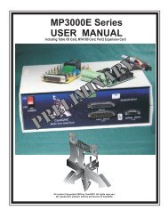
BladeRunner Master Controller Interface Block Diagram FIGURE 5<br />
PC<br />
Parallel<br />
Ports<br />
Mounted at plasma or VFD<br />
Single DB9 Cable<br />
THC<br />
SENSOR<br />
EXpansion Module Option (only)<br />
Sensor Cable<br />
OR<br />
BladeRunner Control Box<br />
Serial<br />
Port<br />
Single DB9 Cable<br />
SPINDLE<br />
SPEED<br />
TABLE I/O<br />
Single DB25 Cable<br />
DB9 Cable<br />
EZPlug G251-4<br />
Four axis Stepper<br />
Driver<br />
Table Limits<br />
Homes<br />
Safety<br />
Remote E-Stop<br />
REMOTE<br />
TABLE I/O<br />
CARD<br />
20A Relay<br />
10A Relay<br />
AC or DC Loads<br />
Mounted on table<br />
POWER SUPPLY<br />
Stepper motors/cables POWER COMMANDER<br />
HARDWARE SETUP
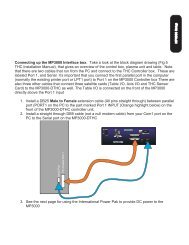
Connecting up the BladeRunner Control box.<br />
Take a look at the block<br />
diagram, that gives an overview of the control box,. Note that there are two<br />
cables that run from the PC and connect to the BladeRunner box. These are<br />
labeled Port 1, and Serial It's important that you connect the first parallel port in<br />
the computer (normally the existing printer port or LPT1 port) to Port 1 on the<br />
BladeRunner Controller box There are also other cables that connect three<br />
satellite cards (Table I/O, and THC Sensor Card/VFD Interface Card) to the<br />
BladeRunner-DTHC or Spindle Speed as well. The Table I/O is connected on the<br />
front of the BladeRunner directly above the Port 1 input. The other end connects<br />
to the DB25 plug on the Table I/O card (inside the PowerCommander on units<br />
with upgraded Power Supply)<br />
1. Install a DB25 Male to Female extension cable (All pins straight through)<br />
between parallel port (PORT1 on the PC to the part marked Port 1 INPUT<br />
(Orange highlight below) on the front of the MP3000-DTHC controller unit.<br />
2. Install a straight through DB9 cable (not a null modem cable) from your<br />
Com1 port on the PC to the Serial port on the MP3000-DTHC<br />
PC Parallel Port 1<br />
Serial Port<br />
ON<br />
OFF<br />
AC<br />
POWER<br />
PULSE MONITOR<br />
X Y Z A<br />
G251-4<br />
CandCNC<br />
DTHC SPS<br />
Multi-Axis Stepper Controller Dragon Expansion<br />
:<br />
ll<br />
STATUS<br />
FAULT LD<br />
TABLE I/O INPUT<br />
Port1 INPUT<br />
To PC<br />
AUX<br />
POWER<br />
ON OFF<br />
MOTOR DC<br />
EXPANSION CARD<br />
To Remote Sensor<br />
Push<br />
Read<br />
CP PWR<br />
TEST<br />
SERIAL INPUT<br />
To PC<br />
3. Plug the BladeRunner into a standard 110VAC to 120VAC 60HZ wall<br />
socket.(units ordered with the International 220VAC 50/60HZ configuration<br />
will not have AC plugs. They will be marked on the back as 220VAC units<br />
HARDWARE SETUP
9 pin Control cable shown<br />
will be plugged in later<br />
Use DB25 male to female<br />
cable to plugin PORT1 cable.<br />
Plug male end into PC<br />
parallel Port. Plug female<br />
into front of BladeRunner.<br />
Tighten both holding screws<br />
finger tight on both ends of<br />
the cable<br />
HARDWARE SETUP<br />
Plug-in Table I/O cable to<br />
front of<br />
BladeRunner.<br />
Tighten screw finger tight.
Plug other end of Table I/O cable into<br />
DB25 connector on the end of the<br />
Power Commander Box (Power<br />
Supply)<br />
DC POWER<br />
36-48VDC<br />
Connect Db9 cable between Power Commander and<br />
Back of BladeRunner. This cable is required to let the BladeRunner Motor DC<br />
buttons on the front turn power on and off inside the Power Commander Box<br />
SERIES C<br />
To POWER<br />
COMMANDER<br />
A<br />
PORT2 EXPANSION<br />
Z<br />
A1 A2 B1 B2 A1 A2 B1 B2 A1 A2 B1 B2 A1 A2 B1 B2<br />
Y<br />
MAX PHASE CURRENT 3.5A<br />
G251-4<br />
X<br />
:<br />
ll<br />
AC<br />
POWER<br />
120VAC<br />
60 HZ<br />
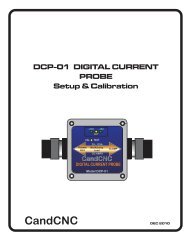
HARDWARE SETUP
SERIES C<br />
DC POWER<br />
36-48VDC<br />
To POWER<br />
COMMANDER<br />
A<br />
DB25 Ribbon Cable Adapter<br />
to UBOB Port2 Interface Header<br />
PORT2 EXPANSION<br />
Z<br />
A1 A2 B1 B2 A1 A2 B1 B2 A1 A2 B1 B2 A1 A2 B1 B2<br />
Y<br />
MAX PHASE CURRENT 3.5A<br />
REAR PANEL BladeRunner <strong>II</strong><br />
G251-4<br />
X<br />
:<br />
ll<br />
AC<br />
POWER<br />
120VAC<br />
60 HZ<br />
50VDC (max) 6 to 12A<br />
Connects to matching plug on Power<br />
Supply or Power Commander Box<br />
NOTE:<br />
The Port 2 Expansion Plug is used to interface with the OPTIONAL port 2 card<br />
supplied with the MPG101B Hand Controller. Please refer to that manual for the<br />
setup and testing of the MPG101B and the connections to the Port2 Expansion Plug<br />
via a DB25 cable and the DB25 input of the Port 2 card. A second parallel port<br />
(typically an add-in expansion card in the PC) is needed to get signal interface to Port<br />
2 signals. See the PC Hardware Setup Section for setting up a second parallel port.<br />
HARDWARE SETUP