T-WALL - Shaw Precast Solutions
T-WALL - Shaw Precast Solutions
T-WALL - Shaw Precast Solutions
- No tags were found...

Create successful ePaper yourself
Turn your PDF publications into a flip-book with our unique Google optimized e-Paper software.
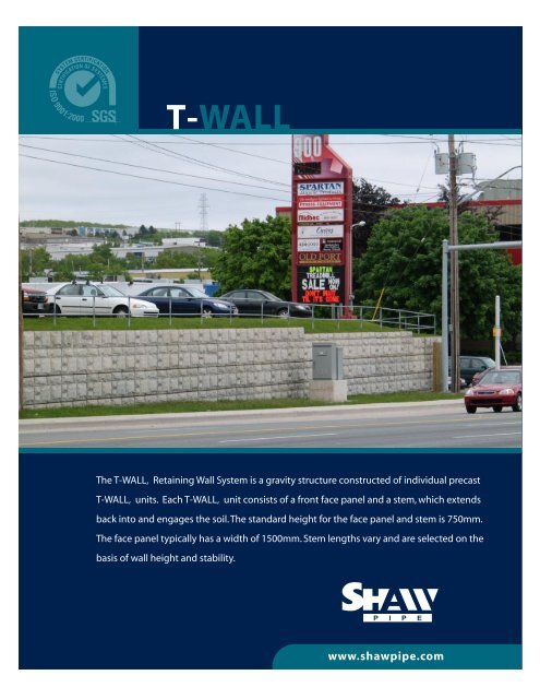
T-<strong>WALL</strong>The T-<strong>WALL</strong>‚ Retaining Wall System is a gravity structure constructed of individual precastT-<strong>WALL</strong>‚ units. Each T-<strong>WALL</strong>‚ unit consists of a front face panel and a stem, which extendsback into and engages the soil. The standard height for the face panel and stem is 750mm.The face panel typically has a width of 1500mm. Stem lengths vary and are selected on thebasis of wall height and stability.www.shawpipe.com
T - W A L LThe T-<strong>WALL</strong>‚ Retaining Wall System is a gravity structureconstructed of individual precast T-<strong>WALL</strong>‚ units. Each T-<strong>WALL</strong>; unit consists of a front face panel and a stem,which extends back into and engages the soil. Thestandard height for the face panel and stem is 750mm.The face panel typically has a width of 1500mm. Stemlengths vary and are selected on the basis of wall heightand stability.The design for each T-<strong>WALL</strong>‚ structure is carried out byProfessional Engineers as part of the wall supply service.The wall structure is checked to ensure adequate safetyfactors for overturning, pullout and sliding. The bearingpressure along the underside of the wall is calculatedusing the Meyerhof method and checked against theallowable bearing capacity. Stamped shop drawings areavailable for each projectS H A W P I P E P R O D U C T G U I D E A N D T E C H N I C A L R E F E R E N C E M A N U A LBOX CULVERTS SECTION 6www.shawpipe.com
T-<strong>WALL</strong>T-WallThe modular nature of the T-<strong>WALL</strong>‚ unit providesflexibility for wall layout and allows on-site modificationswhen unexpected conditions such as rock outcropsor existing services are encountered. SHAW PIPEprovides the joint materials, filter fabric, special liftingdevices and all other materials required for completeon-site wall erection.SHAW PIPE offers one on one consultation for layoutand design of T-<strong>WALL</strong>‚ projects. We will assist onthe project from the conceptual stage, through to finaldesign and on-site installation.APPLICATIONST-<strong>WALL</strong>‚ provides cost effective solutions to anumber of site conditions commonly encountered incommercial, industrial and public works. Typicalapplications include:• Highways, roads, and parking lots• Bridge abutments and wingwalls• Site development• Bank stabilization• Retaining wallsT-<strong>WALL</strong> ® UNIT WEIGHTSSTEM LENGTH (mm) WEIGHT (kg)1219 7261829 8392438 9533048 10663658 11794267 13154877 14295486 15426096 1656RETAINING <strong>WALL</strong>SSHAW PIPE PRODUCT GUIDE AND TECHNICAL REFERENCE MANUAL1RETAINING <strong>WALL</strong>S T-<strong>WALL</strong> SECTION 7www.shawpipe.comREF-97/98-10/06
T-<strong>WALL</strong>Construction ProceduresRetaining Wall Structures T-WallAll the components required for complete on-siteerection of a T-<strong>WALL</strong>‚ structure are supplied anddelivered to site by SHAW PIPE. A SHAW PIPErepresentative is available at the start of wallerection to provide hands on technical assistance.An overview of the straightforward constructionsteps for a T-<strong>WALL</strong>‚ structure follows:FOUNDATION PREPARATION: The foundationis prepared by grading level and proof rolling thearea where the T-<strong>WALL</strong>‚ units are to be placed.Unsuitable materials below subgrade are removedand replaced with compacted granular backfill.LEVELING PAD: A nonstructural, non-reinforcedconcrete leveling pad is placed along the line ofthe wall face to provide a working platform forplacement of the T-<strong>WALL</strong>‚ units. A chalk line isestablished on the leveling pad to mark the frontface of the wall.BACKFILLING: Prior to initial backfilling a300mm wide filter fabric is cut into lengths equalto the height of the wall at each vertical joint.These strips are placed across the vertical jointsbetween the units to prevent migration of thebackfill material through the joints. The Backfillmaterial is dumped directly on the tops of thestems to fill both sides equally and prevent lateralmovement of the unit. The backfill is compactedin 300mm lifts.SUBSEQUENT T-<strong>WALL</strong>‚ COURSES: Jointmaterial is placed in the horizontal joints betweenthe units at the front face to prevent concrete toconcrete contact and to act as a gasket againstloss of fines through these joints. <strong>Precast</strong> shearkeys are placed in the blockouts in the top ofthe stems to provide an alignment guide andprevent movement of the units during backfillling.Backfilling and compaction of each lift of T-<strong>WALL</strong>‚units is completed before the next course isstarted.FIRST T-<strong>WALL</strong>‚ COURSE: Staring at a fixed pointsuch as a corner of the wall or an existing structurethe first course of units is set using the chalk lineon the leveling pad to line up the front faces.RETAINING <strong>WALL</strong>S2SHAW PIPE PRODUCT GUIDE AND TECHNICAL REFERENCE MANUALRETAINING <strong>WALL</strong>S T-<strong>WALL</strong> SECTION 7www.shawpipe.comREF-99-10/06
T-<strong>WALL</strong>T-Wall Advantages:A T-<strong>WALL</strong>‚ STRUCTURE WILL PROVIDE:A HIGH QUALITY PRODUCT: Fabrication of the T-<strong>WALL</strong>‚ units by experienced crews in a controlledenvironment ensures a high quality product. Units arecast in the plant under comprehensive quality controleliminating the drawbacks imposed by weather andsite conditions.ECONOMY: T-<strong>WALL</strong>‚ structures are cost competitivewith traditional cast in place retaining walls.QUICK AND EASY ON-SITE INSTALLATION: Theinstallation of a T-<strong>WALL</strong>‚ structure involves preparationof the site, placement and backfilling of wall units.Depending on project size, preparation of the site maybe completed in a matter of hours. Placement of wallunits can be carried out by on site equipment such asa large excavator and is a straight forward and rapidoperation.REDUCED WATER CONTROL COSTS: On projectswhere the work site involves a water course, a precaststructure eliminates the need to maintain a dry sitefor the entire duration of the project reducing watercontrol requirements and costs.DURABILITY: <strong>Precast</strong> concrete products have allthe durability advantages of high quality concrete,without the concern of breakdown of protectivecoatings, corrosion or other problems associatedwith other materials.EASE OF INSPECTION: The Purchaser has theoption to inspect the T-<strong>WALL</strong>‚ units at the plant priorto delivery. With cast in place structures, deficienciessuch as low concrete strength represent a costlyproblem as the product is already in placeSCHEDULE: <strong>Precast</strong> fabrication of T-<strong>WALL</strong>‚ reducesthe amount of work on-site and possible impact ofweather on project schedules. The wall units can beinstalled, backfilled and placed into service immediatelyupon delivery to the site. T-<strong>WALL</strong>‚ units can bepreordered to allow projects to proceed on-site in earlyspring.RETAINING <strong>WALL</strong>SSHAW PIPE PRODUCT GUIDE AND TECHNICAL REFERENCE MANUAL3RETAINING <strong>WALL</strong>S T-<strong>WALL</strong> SECTION 7www.shawpipe.comREF-100-10/06
T-<strong>WALL</strong>VERTICAL T-<strong>WALL</strong>S – LEVEL EMBANKMENTCourseDistancefrom top ofwall (mm)<strong>WALL</strong> HEIGHT (mm)2286 3048 3810 4572 5334 6096 6858 7620 8382STEM LENGTH (mm)1 762 1219 1219 1219 1219 1219 1219 1219 1219 12192 1524 1219 1219 1219 1219 1219 1219 1219 1219 12193 2286 1829 1829 1829 1829 1829 1829 1829 1829 18294 3048 1829 1829 1829 1829 1829 1829 1829 18295 3810 2438 2438 2438 2438 2438 2438 24386 4572 3048 3048 3048 3048 3048 30487 5334 3048 3048 3048 3048 30488 6096 3658 3658 3658 36589 6858 4267 3658 365810 7620 4267 426711 8382 4877RETAINING <strong>WALL</strong>SVERTICAL T-<strong>WALL</strong>S – SLOPED EMBANKMENTCourseDistancefrom top ofwall (mm)<strong>WALL</strong> HEIGHT (mm)2286 3048 3810 4572 5334 6096 6858 7620 8382STEM LENGTH (mm)1 762 1219 1219 1219 1219 1219 1219 1219 1219 12192 1524 1219 1219 1219 1219 1219 1219 1219 1219 12193 2286 1829 1829 1829 1829 1829 1829 1829 1829 18294 3048 2438 2438 2438 2438 2438 2438 2438 24385 3810 3048 3048 2438 2438 2438 2438 24386 4572 3658 3048 3048 3048 3048 30487 5334 3658 3658 3658 3658 36588 6096 4267 4267 4267 42679 6858 4877 4877 487710 7620 5486 548611 8382 60964SHAW PIPE PRODUCT GUIDE AND TECHNICAL REFERENCE MANUALRETAINING <strong>WALL</strong>S T-<strong>WALL</strong> SECTION 7www.shawpipe.comREF-101-10/06