
Create successful ePaper yourself
Turn your PDF publications into a flip-book with our unique Google optimized e-Paper software.
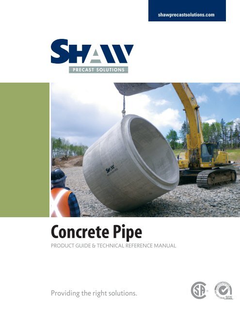
shawprecastsolutions.com<strong>Concrete</strong> <strong>Pipe</strong>PRODUCT GUIDE & TECHNICAL REFERENCE MANUALProviding the right solutions.
During the last decade, owners and engineers have becomevery conscious about design flows, infiltration and economyof buried pipeline systems with performance being the mainconsideration. In this respect one should pay meticulousattention to manufacturers’ qualifications since the qualityand dimensional accuracy of pipe are entirely dependent uponthe manufacturer’s equipment and quality control.SHAW PRECAST SOLUTIONS manufactures culvert andstorm sewer pipe for clear water drainage. Gaskets arecommonly used on the joints but this pipe has not undergonethe rigorous hydrostatic testing performed on the pretestedsanitary pipe.SHAW PRECAST SOLUTIONS manufactures pretestedsanitary sewer pipe for use with a confined gasket to keepsewage waste inside and ground water outside. Each sectionof pipe must pass all of our quality control tests before it iscertified to leave the plant. Our “TESTED” stamp assures youthat section of pipe has qualified and passed our rigoroustests.REVISED November 13, 20122 SHAW PRECAST SOLUTIONS | CONCRETE PIPE
TYPICAL PIPE JOINT DIMENSIONSshawprecastsolutions.com300MM - 750MM DIAMETER PIPE1350MM, 1500MM (C-WALL)2400MM DIAMETER PIPENOTE:Properly specified and inspected pipe,correct laying and jointing procedures,careful bedding, backfilling, and compactionall contribute to a satisfactorilyinstalled, testable sanitary pipeline.900MM - 1500MM (B-WALL) DIAMETER PIPE 3000MM, 3600MM DIAMETER PIPE<strong>Shaw</strong> <strong>Precast</strong> <strong>Solutions</strong> recommendsthat for sanitary pipe installations,good practice dictates that the first 100meters of pipe installed by each crewshould be immediately tested and notmore than 300 meters of pipeline percrew should be untested at any time.PIPE SIZE Wallletter mm in production Type ID OD WT A B C D E F G H J K L M N GASKET WEIGHT300 12 P3 B 304.80 406.40 50.80 88.90 41.38 55.46 165.10 126.49 46.04 34.65 114.30 44.45 44.45 5.08 6.31 16.15 TSS 385375 15 P3 B 381.00 495.30 57.15 88.90 47.10 56.08 165.10 143.93 52.39 40.37 114.30 44.45 44.45 5.08 6.93 16.78 TSS 502450 18 P3 B 457.20 584.20 63.50 88.90 47.10 62.43 165.10 125.11 45.54 40.37 114.30 44.45 44.45 5.08 13.28 23.13 TSS 700525 21 P3 B 533.40 673.10 69.85 88.90 47.10 62.43 177.80 109.04 39.69 40.37 114.30 44.45 44.45 5.08 19.63 29.48 TSS 837600 24 P3 B 609.60 762.00 76.20 88.90 47.10 62.43 177.80 91.59 33.34 40.37 114.30 44.45 44.45 5.08 25.98 35.83 TSS 1042750 30 P3 B 762.00 939.80 88.90 88.90 50.80 69.85 177.80 87.23 31.75 44.07 114.30 44.45 44.45 5.08 34.99 44.83 TSS 1815900 36 P3 C 914.40 1155.70 120.65 88.90 50.80 69.85 N/A N/A N/A 44.07 114.30 44.45 44.45 5.08 66.74 76.53 TSS 2370A 1050 42 P3 B 1066.80 1295.40 114.30 107.95 52.54 61.76 N/A N/A N/A 43.43 133.35 63.50 44.45 7.62 58.48 70.87 TSS 2632E 1200 48 P3 B 1219.20 1473.20 127.00 107.95 62.06 64.94 N/A N/A N/A 52.96 133.35 63.50 44.45 7.62 61.66 74.04 TSS 32601350 54 VUP B 1371.60 1651.00 139.70 108.00 58.40 81.30 N/A N/A N/A 56.10 105.70 N/A N/A N/A N/A 83.60 ORING 41401500 60 P3 B 1524.00 1828.80 152.40 120.65 64.72 87.68 N/A N/A N/A 55.61 146.05 63.50 57.15 7.62 84.40 96.79 TSS 4742K 1500 60 WC C 1524.00 1866.80 171.40 120.70 64.70 106.70 N/A N/A N/A 62.40 118.40 N/A N/A N/A N/A 109.00 TSS 48181500 60 VUP C 1524.00 1866.80 171.40 120.70 64.70 106.70 NA NA NA 62.40 118.40 NA NA NA NA 102.70 ORING 4818L 1800 72 VUP C 1828.80 2222.60 196.90 133.40 92.10 104.80 N/A N/A N/A 89.70 131.00 N/A N/A N/A N/A 107.20 ORING 7725R 2100 84 VUP C 2133.60 2578.20 222.30 127.00 87.30 135.00 N/A N/A N/A 84.10 123.80 N/A N/A N/A N/A 138.20 ORING 99622400 96 VUP B 2438.40 2895.60 228.60 127.00 101.20 127.40 N/A N/A N/A 98.80 127.00 N/A N/A N/A N/A 129.80 ORING 10385Q 2400 96 WC C 2438.40 2933.70 247.60 127.00 101.20 127.40 N/A N/A N/A 98.80 127.00 N/A N/A N/A N/A 129.80 TSS 11587T 3000 120 WC C 3048.00 3657.60 304.80 152.40 110.76 194.04 N/A N/A N/A 100.50 152.40 69.85 N/A 8.99 N/A 204.30 TSS 20757W 3600 144 WC SP 3658.00 4470.00 406.00 152.00 207.34 194.97 N/A N/A N/A 193.83 152.00 69.80 82.20 8.90 N/A 211.97 TSS 31967SHAW PRECAST SOLUTIONS | CONCRETE PIPE 3
FITTINGS - TEES / WYES AND PIPE BENDSFITINGS - TEES (90) AND WYES (45)300 Ø to 3000 Ø*STANDARD ANGLED PIPE BENDS300 Ø to 3000 Ø*ABRANCH PIPE LINEEFDMAIN PIPE LINEBGBCACSTANDARD PIPE LENGTHTEE (90)D90° BENDTHREE PIECE ONLYEADBRANCH PIPE LINEFGMAIN PIPE LINECBBSTANDARD PIPE LENGTHWYE (45)CDTHREE PIECE BEND(45° to 90°)EGBDTWO PIECE BEND(5° to 45°)REVISED November 13, 2012*PIPE DIAMETERS & ANGLES AS SPECIFIED BY CONSULTANT.4 SHAW PRECAST SOLUTIONS | CONCRETE PIPE
shawprecastsolutions.comCurved <strong>Pipe</strong> AlignmentChanges in direction or grade of sewer lines or culverts can beaccomplished by laying pipe on a curved alignment. Curvedalignments can be accommodated in two ways, by deflectingstraight pipe sections at each joint, or using speciallymanufactured radius pipe.DEFLECTED STRAIGHT PIPEIn a straight pipeline alignment, the distance betweenadjacent sections of pipe is essentially uniform around thecircumference of the joint. Gradual curved alignment canbe accommodated by opening up the joint on one side by aspecified amount to achieve the required radius of curvature.To maintain a watertight joint using a rubber gasket joint,ASTM C-443 recommends that the maximum opening (orpull) be 13mm. In installations where watertight integrityis not a concern, the maximum pull is limited by the jointdimensions of the pipe.The following chart provides the minimum radius possiblewhich can be achieved using <strong>Shaw</strong> <strong>Precast</strong> <strong>Solutions</strong> standardpipe, and using a maximum pull of 13mm at each joint.Nominal <strong>Pipe</strong>CURVED PIPE SIZESRadius of CurvatureSize (mm) (m) (ft)300 mm 80 m 262.4 ft375 mm 97.5 m 319.9 ft450 mm 115 m 377.3 ft525 mm 132.5 m 434.7 ft600 mm 150 m 492.1 ft750 mm 185 m 607.0 ft900 mm 227.5 m 746.4 ft1050 mm 255.0 m 836.6 ft1200 mm 290.0 m 951.5 ft1350 mm 325.0 m 1066.3 ft1500 mm 360.0 m 1181.2 ft1800 mm 437.5 m 1435.4 ft2100 mm 507.5 m 1665.1 ft2400 mm 570.0 m 1870.2 ft3000 mm 702.3 m 2304.0 ft3600 mm 861.6 m 2826.8 ftRadius <strong>Pipe</strong>Radius pipe, also referred to as beveled or mitered pipe, isused to construct pipelines which require a short radius ofcurvature. The pipe is manufactured by dropping the spigotring on one side, resulting in one side of the pipe being longerthan the other. The deflection angle is accommodated at thejoint. The maximum angular deflection obtainable is governedby the joint configuration and the method of manufacture.<strong>Shaw</strong> <strong>Precast</strong> <strong>Solutions</strong> manufactures radius pipe for nominalpipe sizes from 1350ømm to 2400ømm.The following table provides the minimum radius obtainablefor all pipe sizes, using a maximum drop of 150mm.Where the maximum drop will vary for each size of pipemanufactured, we recommend that designers consult withour staff to determine the suitability of radius pipe for therequired curvature. Where a shorter radius of curvature isrequired, bends with a minimum 10 degree angle should besubstituted.Nominal <strong>Pipe</strong>RADIUS PIPE SIZESRadius of CurvatureSize (mm) (m) (ft)1350 mm 26.3 m 86.2 ft1500 mm 29.1 m 95.4 ft1800 mm 35.3 m 116.0 ft2100 mm 41.0 m 134.5 ft2400 mm 46.1 m 151.1 ft3000 mm 56.7 m 186.0 ft3600 mm 71.6 m 234.9 ftSHAW PRECAST SOLUTIONS | CONCRETE PIPE 5
CONCRETE PIPE FOR JACKINGThe jacking method of installing concrete pipe is now wellestablished. It has obvious advantages in areas where it isimpossible or undesirable to disturb the overlying surface.Design information and case histories of this method arereadily available.Practical working space limitations require the use of at least900mm diameter pipe. It is preferable to use pipe with noincrease in outside diameter at the bell, in order to reduceproblems with grade alignment.The cross sectional area of all “B-wall” pipe is more thanadequate to resist axial loading due to normal jackingpressures. For unusually high jacking pressures or excessiveunit frictional forces, higher concrete compressive strengthscan be specified, typically up to 41 MPa (6000 psi).Designers should consult with our engineering staff if highercompressive strengths are required.It is extremely important to prevent localized stressconcentrations by maintaining uniform distribution of theaxial load around the circumference of the pipe wall andensuring the ends of the pipe are aligned with the tunnelaxis. It is also important that the pipe being used meets thedimensional tolerances of the specified standards, to ensurethat the ends of the pipe are square to the tunnel axis. Acushioning material should be used at the pipe joints toproperly distribute the jacking force through the jackingframe to the pipe.Further information on concrete pipe for jacking is availablefrom our design staff.REVISED November 13, 20126 SHAW PRECAST SOLUTIONS | CONCRETE PIPE
shawprecastsolutions.comCIRCULAR HALF PIPE ANDPERFORATED PIPECIRCULAR HALF PIPESTANDARD PIPE LENGTHCHANNEL WIDTHPERFORATED PIPE (Available in all pipe sizes)60°60°HOLE QUANTITY& DIAMETER ASSPECIFIEDSHAW PRECAST SOLUTIONS | CONCRETE PIPE 7
FISH & FLOW DISSIPATION WEIRSINSTALLED IN CIRCULAR PIPE SECTIONSPLAN VIEW AT CENTRE LINE OF PIPEWeir dimensions to suit projectspecifications.OPENINGWIDTHLONGITUDINAL SECTION AT CENTRE LINE OF PIPEFish weirs can be installedin circular pipe sections from900mm to 3600mm dia.STANDARD PIPE LENGTHWEIR LOCATIONWEIR HEIGHT 250TRANSVERSE SECTIONSFish weirs can also be installed in channelhalf pipe sections, box culvert, and flatbottom pipe sections.CHANNEL HALF PIPESTANDARD PIPEREVISED November 13, 20128 SHAW PRECAST SOLUTIONS | CONCRETE PIPE
shawprecastsolutions.comFISH & FLOW DISSIPATION WEIRSTYPICAL DIMENSIONSSTANDARD WEIR ASTANDARD PIPE LENGTH405100 205 100100 15020040020030010020mm CHAMFERFLOW300100 200FLOW100 150250TRANSVERSE ELEVATIONPLAN VIEW - WEIRSECTION AT C L OF WEIRSTANDARD WEIR BSTANDARD PIPE LENGTH45095 260 95100100260450100 10020020mm CHAMFERFLOW200100 100FLOW100 100200TRANSVERSE ELEVATIONPLAN VIEW - WEIRSECTION AT C L OF WEIRSHAW PRECAST SOLUTIONS | CONCRETE PIPE 9
FISH & FLOW DISSIPATION WEIRSTYPICAL DIMENSIONSSTANDARD WEIR CSTANDARD PIPE LENGTH500100 300 10026020mm CHAMFER300100 200100 200500200300100FLOWTRANSVERSE ELEVATIONSECTION AT C L OF WEIRREVISED November 13, 2012FLOW100 200300PLAN VIEW - WEIRSTANDARD WEIR DSTANDARD PIPE LENGTH700500500 20mm CHAMFER300100 200100 200700200100FLOWFLOW100 200300TRANSVERSE ELEVATIONPLAN VIEW - WEIRSECTION AT C L OF WEIR10 SHAW PRECAST SOLUTIONS | CONCRETE PIPE
shawprecastsolutions.comFISH & FLOW DISSIPATION WEIRSTYPICAL DIMENSIONSSTANDARD WEIR ESTANDARD PIPE LENGTH15020mm CHAMFER300100 200100350150100150100150350200100FLOW150 200350FLOWTRANSVERSE ELEVATIONPLAN VIEW - WEIRSECTION AT C L OF WEIRSHAW PRECAST SOLUTIONS | CONCRETE PIPE 11
REVISED November 13, 201212 SHAW PRECAST SOLUTIONS | CONCRETE PIPE
shawprecastsolutions.comSHAW PRECAST SOLUTIONS | CONCRETE PIPE 13
REVISED November 13, 201214 SHAW PRECAST SOLUTIONS | CONCRETE PIPE