Precast Headwall Install Guide - Shaw Precast Solutions
Precast Headwall Install Guide - Shaw Precast Solutions
Precast Headwall Install Guide - Shaw Precast Solutions
- No tags were found...

You also want an ePaper? Increase the reach of your titles
YUMPU automatically turns print PDFs into web optimized ePapers that Google loves.
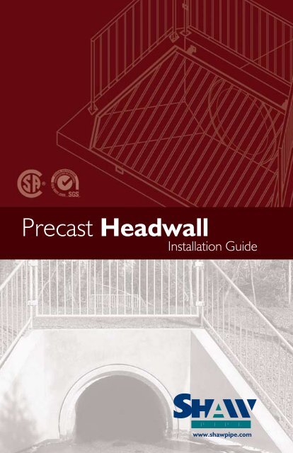
<strong>Precast</strong> <strong>Headwall</strong><strong>Install</strong>ation <strong>Guide</strong>www.shawpipe.com
Table of ContentsGeneral ..................................................................................................2Components ..........................................................................................2Handling, Storage and Transportation......................................................3Construction and <strong>Install</strong>ation ...................................................................4HEADWALLS1P R E - C A S T H E A D W A L L I N S T A L L A T I O N G U I D Ewww.shawpipe.com
2. Handling, Storage & TransportationCare must be exercised when handling and moving Pre-cast units. Theseunits are heavy and their momentum is not easily restrained. The Pre-Cast<strong>Headwall</strong> is equipped with four “cast in” 4 Ton Dayton/Richmond Swift LiftAnchors that must all be utilized when handling.HEADWALLSThe pre-cast headwall unit must have at least two (2) pieces of dunnageunder the width of the unit when stored or transported. This dunnage shouldbe located under the lift anchor locations to minimize stresses on the structure.3P R E - C A S T H E A D W A L L I N S T A L L A T I O N G U I D Ewww.shawpipe.com
3. Construction and <strong>Install</strong>ationCut and install the section of pipe that the headwall will encompass. Leavethis last (or first) section of pipe free from backfill.Place and compact a 300mm thick bed of free draining structural fill to theunderside of the headwall elevation. Compact to a minimum allowablebearing capacity of 100 kPa.HEADWALLSP R E - C A S T H E A D W A L L I N S T A L L A T I O N G U I D E4www.shawpipe.com
Using the <strong>Shaw</strong> supplied connection brackets, drop-in anchors and bolts,mechanically fasten the headwall to the pipe in three locations from theback of the headwall. These locations are the crown and the spring-lineon each side of the pipe. It is imperative that these brackets areinstalled as they are an integral part of the <strong>Shaw</strong> Pre-Cast <strong>Headwall</strong>System.• Using appropriate grout, fill in void between reinforced concrete pipe andheadwall and also fill in lift anchor pockets.• Backfill pipe section first and then proceed to backfill headwall. Maintain a300mm wide envelope of free draining fill around headwall to drain groundwater.• Place Rip-Rap around or in <strong>Headwall</strong> to provide adequate scour protection.• Do not exceed a 1:2 slope (1, vertical : 2, horizontal) at the top of the headwall.• If required, the galvanized grate is fastened to the <strong>Headwall</strong> with the appropriatehardware.HEADWALLSP R E - C A S T H E A D W A L L I N S T A L L A T I O N G U I D E6www.shawpipe.com