Utility Vault Installation Guide - Shaw Precast Solutions
Utility Vault Installation Guide - Shaw Precast Solutions
Utility Vault Installation Guide - Shaw Precast Solutions

Create successful ePaper yourself
Turn your PDF publications into a flip-book with our unique Google optimized e-Paper software.
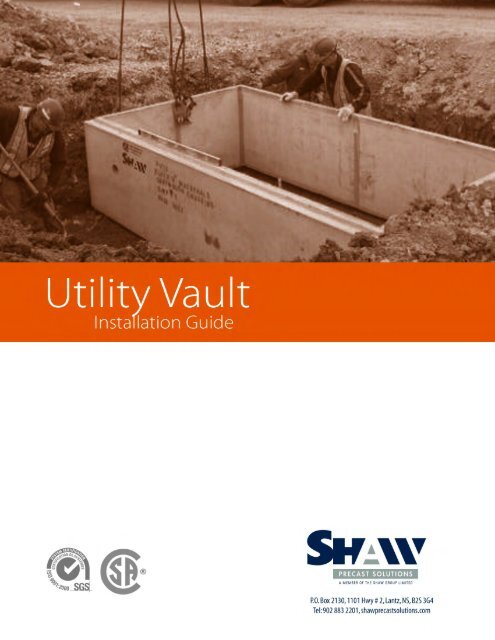
Table of Contents1. General ..................................................................................................................... 22. Handling and Transportation ...................................................................................... 33. Construction and <strong>Installation</strong>....................................................................................... 54. Specifications for Backfilling ......................................................................................... 8UTILITY VAULTINSTALLATIONU T I L I T Y V A U L T I N S T A L L A T I O N G U I D E1
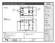
1.General<strong>Shaw</strong> <strong>Utility</strong> <strong>Vault</strong>s are high quality, low maintenance, pre-cast structures that can be used in a varietyof applications such as:• <strong>Utility</strong> meter chambers.• Telecommunications / electrical duct manholes.• Pull pits.• Air / pressure relief chambers.• Valve chamber.• Storage / holding tanks.• Pump chambers.• Etc.<strong>Shaw</strong> Pipe has three standard sizes available for utility structures:• 1500mm wide x 2700 mm long x 2100 mm high• 1800mm wide x 3600 mm long x 2000 mm high• 3000mm wide x 3600 mm long x 2100 mm highStandard units are designed following ASTM C857-95 “Minimum Structural Design Loadingfor Underground <strong>Precast</strong> Concrete <strong>Utility</strong> Structures”, for 600mm of soil cover and CL-625 LiveLoading unless otherwise specified on the shop drawings.Each <strong>Utility</strong> <strong>Vault</strong> consists of a Base and a Cover that are assembled on site with joint materialbetween them to create a complete unit.COVERUTILITY VAULTINSTALLATIONBASE2U T I L I T Y V A U L T I N S T A L L A T I O N G U I D E
2. Handling and TransportationCare must be exercised when handling and moving <strong>Utility</strong> <strong>Vault</strong>s. <strong>Utility</strong> <strong>Vault</strong>s are designed to belifted, stored and transported as they would be installed on site.Spreader Beams are to be used for stripping from the Form, handling in the yard and loading onto thetruck. The use of a spreader beam will prevent unwanted lateral forces applied to the units. All <strong>Utility</strong><strong>Vault</strong>s are to be only lifted by the cast-in lifting anchors that are shown on the shop drawings, any othermethod of lifting may be unsafe or damage the product.Storage of <strong>Utility</strong> <strong>Vault</strong>s shall occur on solid ground that will not settle under the unit’s weight. The unit’sshall be supported by wood dunnage directly below each lift anchor (as a minimum) and shall maintain aminimum of 100mm between the bottom of the structure and the ground. If the ground can resist thestructure’s weight, a Base Section unit may be stacked on top of a Cover Section providing that 50mmseparation between each structure is maintained and the dunnage is located directly below the lift anchors(as a minimum).UTILITY VAULTINSTALLATIONU T I L I T Y V A U L T I N S T A L L A T I O N G U I D E3
<strong>Utility</strong> <strong>Vault</strong> elements are not to be shipped until the full 28 day concrete design strength has been obtained.<strong>Utility</strong> <strong>Vault</strong>s shall always be shipped with their long direction parallel to the truck trailer with the unit’s centreof gravity in line with the vehicles (see project specific shop drawings). Dunnage shall be placed betweenthe trailer deck and the <strong>Utility</strong> <strong>Vault</strong> to prevent damage to the unit. At a minimum, dunnage will be locatedunder each lift anchor point and any other location that a tie-down strap is used. At no time shall the <strong>Utility</strong><strong>Vault</strong> be allowed to deform when being tied down, the unit must be shimmed with the appropriate size pieceof material to prevent deflection.UTILITY VAULTINSTALLATION4U T I L I T Y V A U L T I N S T A L L A T I O N G U I D E
3. Construction and <strong>Installation</strong>The installation/excavation of the <strong>Utility</strong> <strong>Vault</strong> shall be in accordance with all provincial safetylegislation regarding the use of trench cages and/or appropriate back-slopesTo install the <strong>Utility</strong> <strong>Vault</strong>s, equipment rated for the correct capacity shall be used in conjunction with two2-Leg Bridle Hitches at a maximum fleet angle of 60º or a spreader beam. This is to minimize lateral loadon the <strong>Utility</strong> <strong>Vault</strong>. At no time shall the <strong>Utility</strong> <strong>Vault</strong>s be lifted by any other means than by the lift anchorsprovided.UTILITY VAULTINSTALLATIONU T I L I T Y V A U L T I N S T A L L A T I O N G U I D E5
Install Base Section on 300mm of C3 Clear Stone to attain the required bearing capacity noted on theaccompanying shop drawings.Install two 25mm Hamilton Kent “Kent Seal Butyl Rubber Sealant” on the exterior shoulder and interiorspigot of the Base Section, following the manufacture’s installation instructions. After the Top Sectionhas been installed, apply a 300mm wide strip of “Conwrap CS 212” on all four sides of the structure,following the manufacture’s installation instructions.UTILITY VAULTINSTALLATION6U T I L I T Y V A U L T I N S T A L L A T I O N G U I D E
Install Cover onto Base Section ensuring sealant is in contact with both the Cover and Base Sectionaround the perimeter of the joint.Apply 300mm wide ConWrap CS 212 membrane around the joint. This task consists of the applicationof primer and membrane following manufacturer’s directions. See pictures below of the same membranebeing applied to a <strong>Shaw</strong>Span structure.UTILITY VAULTINSTALLATIONU T I L I T Y V A U L T I N S T A L L A T I O N G U I D E7
4. Specifications for BackfillingStructural Backfill used in the <strong>Utility</strong> <strong>Vault</strong> sides shall be of crushed and screened gravel or rock havingthe following Gradation Requirements when following ASTM C117 and C136 test methods:Sieve Size_mPer cent Passing112 000 10040 000 60 - 855 000 25 - 50315 5 - 1580 2 - 7Backfill against the structure shall be completed in layers no greater in depth than 300 mm and compactedto 95 % Standard Proctor. The backfill envelope around the structure should extend a minimum of 600mm around the <strong>Utility</strong> <strong>Vault</strong>’s perimeter. This operation is continued until the fill zone is at an elevation equalto the concrete deck of the <strong>Utility</strong> <strong>Vault</strong>.UTILITY VAULTINSTALLATION8U T I L I T Y V A U L T I N S T A L L A T I O N G U I D E