Technical details System pro M compact®
Technical details System pro M compact®
Technical details System pro M compact®
- No tags were found...

You also want an ePaper? Increase the reach of your titles
YUMPU automatically turns print PDFs into web optimized ePapers that Google loves.
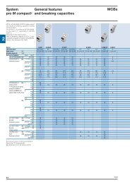
<strong>System</strong><strong>pro</strong> M compact ®<strong>Technical</strong> <strong>details</strong>IndexMCBsTripping characteristics ........................................................................................................ 11/2Limitation of specifi c let-through energy I 2 t .......................................................................... 11/3Peak current Ip .................................................................................................................. 11/10Coordination tables ............................................................................................................ 11/16MCBs internal resistance, power loss and max. permissible earth-fault loop impedance . 11/51Performances at different ambient temperatures, altitudes and frequencies ..................... 11/53Use of MCBs in direct current circuits ............................................................................... 11/55Particular supply sources and loads .................................................................................. 11/56Double tampoprinting of S 200 P ....................................................................................... 11/59Wiring diagrams of MCBs .................................................................................................. 11/60RCDsFunctions and classifi cation criteria for RCDs ................................................................... 11/61Infl uence on RCDs of currents with DC components ....................................................... 11/64Coordination tables ..............................................................................................................11/65Power loss, derating and performance in altitude .............................................................. 11/71Emergency stop using DDA 200 AE series ....................................................................... 11/72Unwanted tripping - AP-R solution .................................................................................... 11/73Use of 4P RCCBs in 3-phase system without neutral pole ............................................... 11/74Type B RCDs ..................................................................................................................... 11/75Wiring diagrams of RCCBs, RCBOs and RCD-blocks ...................................................... 11/77SPDsTerminology of SPD electrical characteristics ................................................................... 11/80Common mode and/or differential mode <strong>pro</strong>tection .......................................................... 11/81Principle of coordination for Surge Protective Devices ...................................................... 11/82Operating diagrams of Surge Protective Devices .............................................................. 11/83Installation rules for SPDs: choice of associatedbreaking devices (fuse/circuit breaker) .............................................................................. 11/85Cabling and installation of Surge Protective Devices in an electrical panel ...................... 11/86MDRCsProtection devicesRD2 residual current monitors ........................................................................................... 11/87Toroidal transformers ......................................................................................................... 11/88E 930 fuse holders ............................................................................................................. 11/90M2160-M2060 fuse switches ............................................................................................. 11/91Command devicesE 259 installation relays ..................................................................................................... 11/92E 250 latching relays ......................................................................................................... 11/93Load management devicesLSS1/2 load shedding switches ......................................................................................... 11/96Max./min. current/voltage ammetric and voltmetric relays ................................................. 11/97Measurement devicesAnalogue and digital measurement instruments and accessories .................................... 11/99Insulation monitors .......................................................................................................... 11/112Other functionsTM/TS bell transformers .................................................................................................. 11/11511ABB11/1
<strong>System</strong><strong>pro</strong> M compact ®<strong>Technical</strong> <strong>details</strong>Tripping characteristicsMCBsTripping characteristicsThermal release Electromagnetic release Acc. to Tripping characteristic Current: Tripping time Currents: Tripping timeand rated current conventional conventional hold tripnon-tripping c. tripping c. current at least atsurgesIEC/EN 60898 B 6 to 63 A 1.13 · I n> 1 h 3 · I n> 0.1 s1.45 · I n< 1 h 5 · I n< 0.1 sC 0.5 to 63 A 1.13 · I n> 1 h 5 · I n> 0.1 s1.45 · I n< 1 h 10 · I n< 0.1 sD 0.5 to 63 A 1.13 · I n> 1 h 10 · I n> 0.1 s1.45 · I n< 1 h 20 · I n< 0.1 sDIN VDE 0660/9.82 K 0.5 to 63 A 1.05 · I n> 1 h1.2 · I n< 1 h not applicableIEC/EN 60947-2 1.05 · I n> 2 h 10 · I n> 0.2 sDIN VDE 0660 1.2 · I n< 1 h 14 · I n< 0.2 s8/69 1.5 · I n< 2 min. Part 101 6.0 · I n> 2 s (T1)DIN VDE 0660/9.82 Z 0.5 to 63 A 1.05 · I n> 1 h1.2 · I n< 1 h not applicableIEC/EN 60947-2 1.05 · I n> 2 h 2 · I n> 0.2 sDIN VDE 0660 1.2 · I n< 1 h 3 · I n< 0.2 s8/69 1.5 · I n< 2 min. Part 101 6.0 · I n> 2 s (T1) The indicated tripping values of electromagnetic tripping devices apply to afrequency range of 16 2/3...60 Hz. In the case of diverging frequencies or directcurrent, see paragraph “Variation of tripping threshold of MCBs, according tonetwork frequency” (page 6/7)Characteristics B, C, D The thermal releases are calibrated to a nominal reference ambient temperature;for Z and K, the value is 20 °C, for B and C = 30 °C. In the case of higher ambienttemperatures, the current values fall by ca. 6 % for each 10 K temperature rise. As from operating temperature (after I 1> 1 h or, as applicable, 2 h).Characteristics K, ZIEC-EN608981.451.13> 63≤ 63> 32≤ 321.2IEC-EN60947-2 1.051201206040604020201010646411Seconds Minutes90453015821402010642Seconds Minutes21402010642110.60.40.60.40.20.1B C D0.20.1ZK0.060.040.060.040.020.020.011 1.5 2 3 4 5 6 8 10 15 20 300.011 1.5 2 3 4 5 6 8 10 15 20 302.5510 20 30multiples of rated current10 14 18multiples of rated current11/2 ABB
<strong>System</strong><strong>pro</strong> M compact ®<strong>Technical</strong> <strong>details</strong>Limitation of specifi clet-through energy I 2 tMCBsIUt = 0I 2 1Oscillogram of short-circuitbreaks on two circuit-breakers:1 = traditional non-currentlimiting circuit-breaker2 = current limiting circuitbreakeru B= arc voltage (red)u M= rest voltage (blue)IUI 2K Mt vu BShort-circuit currentred = effective short-circuitcurrent squaredblue = estimated short-circuitcurrent squared (shuntedcircuit-breaker)iK M= maximum values ofsymmetrical componentof short-circuit currentsquaredshaded inred = specifi c let-throughenergy in two casesi Ku MNon-current limiting circuit-breaker2t = 0iK Mt vu Bi Ku MCurrent limiting circuit-breakertttLimitation of specific let-through energyTripping of an installation circuit by circuit-breaker when there is a short-circuit requires a certainamount of time depending on the characteristics of the circuit-breaker and the entity of the short-circuitcurrent. During this period of time, some or all of the short-circuit current fl ows into the installation;the parameter I 2 t defi nes the “specifi c let-through energy”, ie. the specifi c energy that the breakerallows through when there is a short-circuit current Icc during the tripping time t.In this way, we can determine the capacity of a circuit-breaker to limit, ie. break high currents up tothe rated breaking power of the device, by reducing the peak value of the above-mentioned currentsto a value which is considerably lower than the estimated current.This can be achieved using mechanisms which open very rapidly and have the following advantages:- they limit the thermal and dynamic effects both on the circuit-breaker and on the <strong>pro</strong>tected circuit;- they reduce the dimensions of the current-limiting circuit-breaker without reducing breaking capacity;- they considerably reduce ionized gases and sparklers emitted during the short-circuit and thereforethey avoid the danger of ignition and fi res.Irms = perspective simmetrical short-circuit currentMax. withstanding specific let-through energy of cablesSectionmm 2 PVC EPR HEPR50 33,062,500 39,062,500 51,122,50035 16,200,625 19,140,625 25,050,02525 8,265,625 9,765,625 12,780,62516 3,385,600 4,000,000 5,234,94410 1,322,500 1,562,500 2,044,9006 476,100 562,500 736,1644 211,600 250,000 327,1842.5 82,656 97,656 127,8061.5 29,756 35,156 46,010The selection of the cables depends both from the breakers’ specifi c let-through energy and from carrying capacity and voltagedrop of the line.Data of the previous table are referred to the following cables:PVC EPR HEPRFM9 H07RN-F N07G9-KFM9OZ1FTG10OM1N07V-KRG7ORFRORFG7OM1FG7ORDesignationCable’s reference to the standards harmonized Hnational cable recognized by CENELCARated voltage Uo/U 100/100 ≤ Uo/U < 300/300 01300/300 V 03300/500 V 05450/750 V 07750/1000 V 1Insulating materials and non-metallic sheath ethylene-vinylacetate GmineralMpolyvinyl chlorideVConductor’s shape fl exible conductor of a cable for fi xed installation KSome cables on the market are identifi ed with different names according with the designation UNEL 35011.11ABB11/3
<strong>System</strong><strong>pro</strong> M compact ®<strong>Technical</strong> <strong>details</strong>Limitation of specifi clet-through energy I 2 tMCBsI 2 t diagrams - Specific let-through energy value I 2 tThe I 2 t curves give the values of the specifi c let-through energy expressed in A 2 s (A=amps; s=seconds)in relation to the perspective short-circuit current (Irms) in kA.S 931 N-S 941 N-S 951 N-S 971 N, characteristics B and CDS 941 N-DS 951 N-DS 971 N, characteristics B and C2.5 mm 297.656 EPR127.806 HEPR82.656 PVC1.5 mm 246.010 HEPR35.156 EPR29.756 PVC10 5 4 A40 A25 A16 A32 A20 A10 ASpecific let-through energy I 2 t (A 2 s)10 410 36 A2 A10 2 S 931N S 941NDS 941NPerspective short-circuit current (kA)0.5 1.5 2.5 3.5 4.5 5.5 6.5 7.5 8.5 9.5 10.5S 951NS 971NDS 951NDS 971NS 200-S 200 M-S 200 P, characteristics B and CDS 200-DS 200 M, characteristics B and C2.5 mm 297.656 EPR127.806 HEPR82.656 PVC10 550/60 A 32/40 A20/25 A1.5 mm 246.010 HEPR35.156 EPR29.756 PVC13/16 A10 A11I 2 t [A 2 s]10 46 A4 A3 A10 32 A1.6 A1 A1020.1 1Irms [kA]10S 200 S 200 PDS 200S 200 MDS 200 M100For further information about the selection of the cable, please look at the table in page 11/311/4 ABB
<strong>System</strong><strong>pro</strong> M compact ®<strong>Technical</strong> <strong>details</strong>Limitation of specifi clet-through energy I 2 tMCBsS 200-S 200 M-S 200 P, characteristics D-K10 62.5 mm 297.656 EPR127.806 HEPR82.656 PVC10 550/63 A40 A 20/32 A20 A13/16 A1.5 mm 246.010 HEPR35.156 EPR29.756 PVC10 A6 AI 2 t [A 2 s]10 44 A3 A10 32 A1.6 A1 A1020.1 110100S 200 S 200 MS 200 PIrms [kA]S 200 P, characteristic Z10 62.5 mm 21.5 mm 297.656 EPR127.806 HEPR82.656 PVC46.010 HEPR35.156 EPR29.756 PVCI 2 t [A 2 s]10 510 450/63 A32/40 A20/25 A13/16 A10 A6 A4 A3 A1110 32 A1,6 A1 A1020,1 110100Irms [kA]S 200 PFor further information about the selection of the cable, please look at the table in page 11/3ABB11/5
<strong>System</strong><strong>pro</strong> M compact ®<strong>Technical</strong> <strong>details</strong>Limitation of specifi clet-through energy I 2 tMCBsS 280 80-100 A, characteristic B10I 2 t [A 2 s]1100 A2.5 mm 297.656 EPR127.806 HEPR82.656 PVC10 -180 A1.5 mm 246.010 HEPR35.156 EPR29.756 PVC10 -210 -310-41 10Irms [kA]S 280 80-100 A, characteristic C10I 2 t [A 2 s]1100 A2.5 mm 297.656 EPR127.806 HEPR82.656 PVC10 -180 A111.5 mm 246.010 HEPR35.156 EPR29.756 PVC10 -210 -310-41 10Irms [kA]For further information about the selection of the cable, please look at the table in page 11/311/6 ABB
<strong>System</strong><strong>pro</strong> M compact ®<strong>Technical</strong> <strong>details</strong>Limitation of specifi clet-through energy I 2 tMCBsS 280 characteristics K, Z2.5 mm 297.656 EPR127.806 HEPR82.656 PVC2.5 mm 297.656 EPR127.806 HEPR82.656 PVC10 5 K6310 4K50K40K25K3210 510 4Z63Z40K16K10Z16Z101.5 mm 246.010 HEPR35.156 EPR29.756 PVC1.5 mm 246.010 HEPR35.156 EPR29.756 PVCI 2 t (A 2 s)10 3I 2 t (A 2 s)10 310 2K310 210 11Icc (kA)1010 11Icc (kA)10S 290 characteristics C, D10 6OEPM00981.5 mm 2 I 2 t (A 2 s)2.5 mm 297.656EPR127.80682.65646.01035.15629.756HEPRPVCHEPREPRPVC10 510 410 7 1.5.10 4D 100/125 AD 80 AC 100/125 AC 80 A1110 310 310 4Irms (kA)For further information about the selection of the cable, please look at the table in page 11/3ABB11/7
<strong>System</strong><strong>pro</strong> M compact ®<strong>Technical</strong> <strong>details</strong>Limitation of specifi clet-through energy I 2 tMCBsS 800 S characteristics B, C, K and D I 2 t [A 2 s] Irms [kA] 11I 2 t [A 2 s] Irms [kA]11/8 ABB
<strong>System</strong><strong>pro</strong> M compact ®<strong>Technical</strong> <strong>details</strong>Limitation of specifi clet-through energy I 2 tMCBsS 800 N characteristics B, C and D I 2 t [A 2 s] Irms [kA] I 2 t [A 2 s] 11 Irms [kA]ABB11/9
<strong>System</strong><strong>pro</strong> M compact ®<strong>Technical</strong> <strong>details</strong>Peak current IpMCBsLimitation curves - Peak current valuesThe Ip curves give the values of the peak current, expressed in kA, in relation to the perspectivesimmetrical short-circuit current (kA).S 931N-S 941N-S 951N-S 971N, characteristics B and CDS 941-DS 951-DS 971 characteristics B and C10050201032 A 40 AIp [kA]52120A 25 A13A 16 A10 A6 A4 A2 A0.50.2000.2 0.5 1 2 5 10 20 50 100S 931 NIrms [kA]S 941 NDS 941S 951 NS 971 NDS 951DS 9711111/10 ABB
<strong>System</strong><strong>pro</strong> M compact ®<strong>Technical</strong> <strong>details</strong>Peak current IpMCBsS 200-S 200 P, characteristics B-CDS 200-DS 200 M, characteristics B-C100502010550 63 A32 40 A20 25 A13 16 A8 10 AIp [kA]26 A4 A10.53 A2 A1,6 A0,5 1 A0.2000.2 0.5 1 2 5 10 20 50 100S 200 S 200 M S 200 PIrms [kA] DS 200 DS 200 MS 200-S 200 P, characteristics K-D100502050 63 A1032 40 A20 25 AIp [kA]5213 16 A8 10 A6 A4 A113 A12 A1,6 A0.50,5 1 A0.2000.2 0.5 1 2 5 10 20 50 100Irms [kA] S 200 S 200 M S 200 PABB11/11
<strong>System</strong><strong>pro</strong> M compact ®<strong>Technical</strong> <strong>details</strong>Peak current IpMCBsS 200 P, characteristic Z10050201050 63 A32 40 A20 25 AIp [kA]5213 16 A8 10 A6 A4 A10.53 A2 A1,6 A0,5 1 A0.2000.2 0.5 1 2 5 10 20 50 100Irms [kA]S 200 PS 280 80-100 A, characteristic B100502010100 A11Ip [kA]580 A210.50.2000.2 0.5 1 2 5 10 20 50 100Irms [kA]11/12 ABB
<strong>System</strong><strong>pro</strong> M compact ®<strong>Technical</strong> <strong>details</strong>Peak current IpMCBsS 280 80-100 A, characteristic C1005020105100 A80 AIp [kA]210.50.2000.2 0.5 1 2 5 10 20 50 100Irms [kA]11ABB11/13
<strong>System</strong><strong>pro</strong> M compact ®<strong>Technical</strong> <strong>details</strong>Peak current IpMCBsS 800 S characteristics B, C, K and D Ip [kA] Irms [kA] 11Ip [kA] Irms [kA]11/14 ABB
<strong>System</strong><strong>pro</strong> M compact ®<strong>Technical</strong> <strong>details</strong>Peak current IpMCBsS 800 N characteristics B, C and D Ip [kA] Irms [kA] Ip [kA]11 Irms [kA]ABB11/15
<strong>System</strong><strong>pro</strong> M compact ®<strong>Technical</strong> <strong>details</strong>Coordination tablesMCBsBack-up <strong>pro</strong>tectionThe tables given <strong>pro</strong>vide the value (in kA, referring to the breaking capacity according to the IEC60947-2 Standard) for which the back-up <strong>pro</strong>tection among the combination of selected circuitbreakersis verifi ed. The tables cover the possible combinations between ABB SACE Tmax seriesof moulded-case circuit-breakers and those between the above-mentioned circuit-breakers and theABB series of modular circuit-breakers.The values indicated in the tables refer to the voltage:– Vn of 230/240 V AC for coordination with modular S9 circuit-breakers– Vn of 400/415 V AC for all the other coordinations.400 VL1 L2 L3 N400 V400 V230 VL3 NSelective <strong>pro</strong>tectionThe tables given <strong>pro</strong>vide the value (in kA, referring to the breaking capacity according to the IEC60947-2 Standard) for which the selective <strong>pro</strong>tection is verifi ed among the combination of selectedcircuit-breakers. The tables cover the possible combinations between ABB SACE Tmax series ofmoulded-case circuit-breakers, and the ABB series of modular circuit-breakers. The values in thetable represent the maximum value obtainable of discrimination between supply side circuit-breakerand load side circuit-breaker referring to the voltage:– Vn of 230/240 V AC for the S9 circuit-breakers and Vn of 400/415 V AC for the supply sidecircuit-breakers in the coordination between MCB with the modular S9 circuit-breakers (seepicture).– Vn of 400/415 V AC for all the other coordinations.General prescriptions– Function I of the electronic releases of the supply side circuit-breakers must be excluded (I 3inOFF);– The magnetic trip of thermomagnetic (TM) or magnetic only (M) circuit-breakers placed on thesupply side must be 10 x In and regulated to the maximum threshold;– It is of prime importance to check that the settings made by the user for the electronic and thermomagneticrelays of circuit-breakers placed both on the load and supply side do not createintersections on the time-current curves.NoteThe following tables give the breaking capacities at 415 V AC for circuit-breakers SACE Tmax.11Tmax @ 415 V ACVersionIcu [kA]B 16C 25N 36S 50H 70L (T2) 85L (T4, T5) 120V 200CaptionMCB = miniature circuit-breakers (S 9, S 2,S 800)MCCB = moulded-case circuit-breakers(Tmax)– MF (Tmax)– MA (Tmax)EL = electronic release– PR221DS - PR222DS (Tmax)For moulded-case or air circuit-breakers:TM = thermomagnetic release– TMD (Tmax)– TMA (Tmax)M = magnetic only releaseFor miniature circuit-breakers:B = trip characteristic (Im=3...5In)C = trip characteristic (Im=5...10In)D = trip characteristic (Im=10...20In)K = trip characteristic (Im=8...14In)Z = trip characteristic (Im=2...3In)For solutions not shown in these tables, please consult the website:http://bol.it.abb.com or contact ABB SACE11/16 ABB
<strong>System</strong><strong>pro</strong> M compact ®<strong>Technical</strong> <strong>details</strong>Coordination tables:back-upMCBsMCB -MCB @240 V (Two-pole circuit-breakers)Supply s. S200 S200M S200P S200P S 280 S 290 S 800Char. B-C B-C B-C B-C B-C C B-CLoad s. Icu [kA ] 20 25 40 25 20 25 100In [A ] 0.5..63 0.5..63 0.5..25 32..63 80,100 80..125 10..125S 931 N C 4,5 2..40 20 25 40 25 15 15 100S 941 N B,C 6 2..40 20 25 40 25 15 15 100S 951 N B,C 10 2..40 20 25 40 25 15 15 100S 971 N B,C 10 2..40 20 25 40 25 15 15 100S 200 B,C,K,Z 20 0.5..63 25 40 25 100S 200 M B,C,D 25 0.5..63 40 100S 200 P B,C, 40 0.5..25 100D,K,Z 25 32..63 100S 280 B,C 20 80,100S 290 C,D,K 25 80..125S 800 B,C 100 10..125MCCB @415 V -MCB @240 VSupply s.* T1 T1 T1 T2 T3 T2 T3 T2 T2Version B C N N N S S H LLoad s. Char. In [A ] Icu [kA ] 16 25 36 36 36 50 50 70 85S 931 N C 2..25 4.5 16 16 16 20 10 20 10 20 2032,40 4.5 10 10 10 16 10 16 10 16 16S 941 N B,C 2..25 6 16 16 16 20 10 20 10 20 2032,40 6 10 10 10 16 10 16 10 16 16S 951 N B,C 2..25 10 16 16 16 25 16 25 16 25 2532,40 10 16 16 16 16 16 16 16 16 16S 971 N B,C 2..25 10 16 16 16 25 16 15 16 25 2532,40 10 16 16 16 16 16 16 16 16 16*Supply side circuit-breaker 4P (load side circuit branched between one phase and the neutral)MCB -MCB @415 VSupply s. S200 S200M S200P S200P S 280 S 290 S 800 S S 800 NChar. B-C B-C B-C B-C B-C C B-C-D-K B-C-DLoad s. Icu [kA ] 10 15 25 15 6 20 50 36In [A ] 0.5..63 0.5..63 0.5..25 32..63 80,100 80..125 10..125 10..125S 200 B,C,K,Z 10 0.5..63 15 25 15 15 50 36S 200 M B,C,D 15 0.5..63 25 50 36S 200 P B,C, 25 0.5..25 50 36D,K,Z 15 32..63 50 36S 280 B,C 6 80,100S 290 C,D,K 20 (15)* 80..125MCCB -MCB @415 VSupply s. T1 T1 T1 T2 T3 T4 T2 T3 T4 T2 T4 T2 T4 T4Version B C N N N N S S S H H L L VLoad s. Char. In [A ] Icu [kA ] 16 25 36 36 36 36 50 50 50 70 70 85 120 200S 200 B,C,K,Z 0.5..10 10 16 25 30 36 36 36 36 40 40 40 40 40 40 4013..63 10 16 25 30 36 16 36 36 16 40 40 40 40 40 40S 200 M B,C,D 0.5..10 15 16 25 30 36 36 36 50 40 40 70 40 85 40 4013..63 15 16 25 30 36 25 36 50 60 40 60 40 60 40 40S 200 P B,C, 0.5..10 25 30 36 36 36 50 40 40 70 40 85 40 40D,K,Z 13..25 25 36 30 36 50 30 40 60 40 60 40 40 4032..63 15 16 25 30 36 25 36 50 25 40 60 40 60 40 40S 280 B,C 80,100 6 16 16 16 36 16 30 36 16 30 36 30 36 30 30S 290 C,D,K 80..125 20 (15)* 16 25 30 36 30 30 50 30 30 70 30 85 30 30S 800 S B,C,D,K 10..125 50 70 70 85 120 200S 800 N B,C,D 10..125 36 70 70 85 120 200*Only for D characteristic11ABB11/17
<strong>System</strong><strong>pro</strong> M compact ®<strong>Technical</strong> <strong>details</strong>Coordination tables:selectivityMCBsSelective <strong>pro</strong>tectionSelectivity between S 9.. and S 200 upstream and downstream modular circuit-breakersIn the case, selectivity is amperometric and so the selectivity limit is given simply by the magneticthreshold of the upstream breaker, which is fi xed. The selectivity value is obtained if a minimumratio of 1.6 (In upstream/In downstream > 1.6) is observed between the rated currents of the twobreakers.ExampleUpstream circuit-breakerDownstream circuit-breakerSelectivity limitS 200 P, curve D 50 AS 941 N, curve B 10 A10 In=500 A11MCB -S9 @230/240 VSupply s.**S290Char. C DIcu [kA ] 25Load s.* In [A ] 80 100 125 80 100S931N B-C 4.5 2 T T T T T4 T T T T T6 T T T T T10 4 T T T T16 2.5 3.5 3.5 4 T20 1.5 2.5 2.5 3 T25 0.5 0.5 1.5 2 432 0.5 0.5 0.5 1.5 3.540 0.5 0.5 0.5 1.5 3.5S941N B-C 6 2 T T T T T4 5 T T T T6 4.5 5 T 5.5 T10 4 4.5 5 5 516 2.5 3.5 3.5 4 4.520 1.5 2.5 2.5 3 4.525 0.5 0.5 1.5 2 432 0.5 0.5 0.5 1.5 3.540 0.5 0.5 0.5 1.5 3.5S951N B-C 10 2 6 8 9 7 84 5 6 7.5 6 76 4.5 5 6 5.5 610 4 4.5 5 5 516 2.5 3.5 3.5 4 4.520 1.5 2.5 2.5 3 4.525 0.5 0.5 1.5 2 432 0.5 0.5 0.5 1.5 3.540 0.5 0.5 0.5 1.5 3.5S971N B-C 10 2 6 8 9 7 84 5 6 7.5 6 76 4.5 5 6 5.5 610 4 4.5 5 5 516 2.5 3.5 3.5 4 4.520 1.5 2.5 2.5 3 4.525 0.5 0.5 1.5 2 432 0.5 0.5 0.5 1.5 3.540 0.5 0.5 0.5 1.5 3.5*Load side circuit-breaker 1P+N (230/240 V)**For networks with 230/240 V AC ->two-pole circuit-breaker (phase +neutral)for networks at 400/415 V AC ->four-pole circuit-breaker (load side circuit branched between one phase and the neutral)11/18 ABB
<strong>System</strong><strong>pro</strong> M compact ®<strong>Technical</strong> <strong>details</strong>Coordination tables:selectivityMCBsMCB - S 200 @ 400/415 VSupply s. S 290Char.DIcu [kA] 15Load s. In [A] 80 100S 200 C 10 ≤ 2 T T3 T T4 T TB-C 10 6 T T8 T T10 5 813 4.5 716 4.5 720 3.5 525 3.5 532 4.5405063D 10 ≤ 2 T T3 T T4 T T6 T T8 T T10 5 813 3 516 3 520 3 525 432405063K 10 ≤ 2 T T3 T T4 T T6 T T8 T T10 5 816 3 520 3 525 432405063Z 10 ≤ 2 T T3 T T4 T T6 T T8 T T10 5 816 4.5 720 3.5 525 3.5 532 3 4.540 3 4.550 36311ABB11/19
<strong>System</strong><strong>pro</strong> M compact ®<strong>Technical</strong> <strong>details</strong>Coordination tables:selectivityMCBsFuseIm Icu [kA]In [A] 25 32 40 50 63 80 100 125S931N C 4.5 2 1.5 2.5 T T T T T T4.5 4 1 2 T T T T T T4.5 6 1 1.5 4 T T T T T4.5 10 - 1.2 3.5 4 T T T T4.5 16 - 1 3 3.5 T T T T4.5 20 - 1 3 3.5 T T T T4.5 25 - 1 2 3 T T T T4.5 32 - 1 2 3 T T T T4.5 40 - - 1.5 2.5 4 T T TS941N B-C 6 2 1.5 2.5 T T T T T T6 4 1 2 4.5 T T T T T6 6 1 1.5 4 4.5 T T T T6 10 - 1.2 3.5 4 T T T T6 16 - 1 3 3.5 5 T T T6 20 - 1 3 3.5 5 T T T6 25 - 1 2 3 4.5 T T T6 32 - 1 2 3 4.5 5 T T6 40 - - 1.5 2.5 4 5 T TS951N B-C 10 2 1.5 2.5 5 T T T T T10 4 1 2 4.5 5 T T T T10 6 1 1.5 4 4.5 7 T T T10 10 - 1.2 3.5 4 6 T T T10 16 - 1 3 3.5 5 T T T10 20 - 1 3 3.5 5 8 T T10 25 - 1 2 3 4.5 6.5 T T10 32 - 1 2 3 4.5 5 8 T10 40 - - 1.5 2.5 4 5 6.5 TS971N B-C 10 2 1.5 2.5 5 7 T T T T10 4 1 2 4.5 5 8 T T T10 6 1 1.5 4 4.5 7 T T T10 10 - 1.2 3.5 4 6 T T T10 16 - 1 3 3.5 5 9 T T10 20 - 1 3 3.5 5 8 T T10 25 - 1 2 3 4.5 6.5 9 T10 32 - 1 2 3 4.5 5 8 T10 40 - - 1.5 2.5 4 5 6.5 91111/20 ABB
<strong>System</strong><strong>pro</strong> M compact ®<strong>Technical</strong> <strong>details</strong>Coordination tables:selectivityMCBsMCB S 700Im E E E E E E E EIcu [kA] 30 30 30 30 30 30 30 30In [A] 20 25 35 40 50 63 80 100S931N C 4.5 2 T T T T T T T TC 4.5 4 T T T T T T T TC 4.5 6 T T T T T T T TC 4.5 10 T T T T T T T TC 4.5 16 - T T T T T T TC 4.5 20 - - T T T T T TC 4.5 25 - - T T T T T TC 4.5 32 - - - - T T T TC 4.5 40 - - - - - T T TS941N B-C 6 2 T T T T T T T TB-C 6 4 T T T T T T T TB-C 6 6 T T T T T T T TB-C 6 10 T T T T T T T TB-C 6 16 - T T T T T T TB-C 6 20 - - T T T T T TB-C 6 25 - - T T T T T TB-C 6 32 - - - - T T T TB-C 6 40 - - - - - T T TS951N B-C 10 2 T T T T T T T TB-C 10 4 T T T T T T T TB-C 10 6 T T T T T T T TB-C 10 10 T T T T T T T TB-C 10 16 - T T T T T T TB-C 10 20 - - T T T T T TB-C 10 25 - - T T T T T TB-C 10 32 - - - - T T T TB-C 10 40 - - - - - T T TS971N B-C 10 2 T T T T T T T TB-C 10 4 T T T T T T T TB-C 10 6 T T T T T T T TB-C 10 10 T T T T T T T TB-C 10 16 - T T T T T T TB-C 10 20 - - T T T T T TB-C 10 25 - - T T T T T TB-C 10 32 - - - - T T T TB-C 10 40 - - - - - T T T11ABB11/21
<strong>System</strong><strong>pro</strong> M compact ®<strong>Technical</strong> <strong>details</strong>Coordination tables:selectivityMCBs11MCCB @415 V 4p -S9 @240 VSupply s. T1 T2Version B,C,N N, S, H, LRelease TMD TMD,MAIu [A ] 160 160Load s. Char. Icu [kA ] In [A ] 16 20 25 32 40 50 63 80 100 125 160** 160 16 20 25 32 40 50S931N C 4.5 4 T T T T T T T T T T T T T T T T T T6 T T T T T T T T T T T T T T T T T T10 3 3 3 T T T T T T T 3* 3 3 3 T16 3 T T T T T T T 3* 3 T20 3 T T T T T T 3* 325 T T T T T T 3*32 T T T T T 3*40 T T T TS941N B-C 6 4 T T T T T T T T T T T T T T T T T T6 T T T T T T T T T T T T T T T T T T10 3 3 3 4.5 T T T T T T 3* 3 3 3 4.516 3 4.5 5 T T T T T 3* 3 4.520 3 5 6 T T T T 3* 325 5 6 T T T T 3*32 6 T T T T 3*40 T T T TS951N B-C 10 4 T T T T T T T T T T T T T T T T T T6 6 6 6 6 6 6 T T T T T T T T T T T T10 3 3 3 4.5 7.5 8.5 T T T T 3* 3 3 3 4.516 3 4.5 5 7.5 T T T T 3* 3 4.520 3 5 6 T T T T 3* 325 5 6 T T T T 3*32 6 7.5 T T T 3*40 7.5 T T TS971N B-C 10 4 T T T T T T T T T T T T T T T T T T6 6 6 6 6 6 6 12 T T T T T T T T T T T10 3 3 3 4.5 7.5 8.5 T T T T 3* 3 3 3 4.516 3 4.5 5 7.5 T T T T 3* 3 4.520 3 5 6 T T T T 3* 325 5 6 T T T T 3*32 6 7.5 T T T 3*40 7.5 T T TSupply side circuit-breaker 4P (load side circuit branched between one phase and the neutral)Load side circuit-breaker 1P+N (230/240 V)*Value valid only for magnetic only supply side circuit-breaker**Neutral 50%11/22 ABB
<strong>System</strong><strong>pro</strong> M compact ®<strong>Technical</strong> <strong>details</strong>Coordination tables:selectivityMCBsT2T3N,S,H,LN,STMD, MA EL TMD,MA160 25063 80 100 125** 125 160** 160 10 25 63 100 160 63 80 100 125** 125 160** 160 200** 200 250** 250T T T T T T T T T T T T T T T T T T T T T T TT T T T T T T T T T T T T T T T T T T T T TT T T T T T T T T T T T T T T T T T T T T TT T T T T T T T T T T T T T T T T T T T TT T T T T T T T T T T T T T T T T T T T TT T T T T T T T T T T T T T T T T T T T TT T T T T T T T T T T T T T T T T T TT* T T T T T T T* T T T T T T T TT T T T T T T T T T T T T T T T T T T T T T TT T T T T T T T T T T T T T T T T T T T T TT T T T T T T T T T T T T T T T T T T T T T5 T T T T T T T T T 5 T T T T T T T T T T5 T T T T T T T T T 5 T T T T T T T T T T5 T T T T T T T T T 5 T T T T T T T T T TT T T T T T T T T T T T T T T T T T TT* T T T T T T T* T T T T T T T TT T T T T T T T T T T T T T T T T T T T T T TT T T T T T T T T T T T T T T T T T T T T T7.5 8.5 T T T T T T T T T 7.5 8.5 T T T T T T T T T5 7.5 T 7.5 T T T T T T 5 7.5 T 7.5 T T T T T T T5 6 T 6 T T T T T T 5 6 T 6 T T T T T T T5 6 T 6 T T T T T T 5 6 T 6 T T T T T T6 7.5 6 T T T T T T 6 7.5 6 T T T T T T T6* 7.5 T T T T T 6* 7.5 T T T T T T TT T T T T T T T T T T T T T T T T T T T T T TT T T T T T T T T T T T T T T T T T T T T T7.5 8.5 T T T T T T T T T 7.5 8.5 T T T T T T T T T5 7.5 T 7.5 T T T T T T 5 7.5 T 7.5 T T T T T T T5 6 T 6 T T T T T T 5 6 T 6 T T T T T T T5 6 T 6 T T T T T T 5 6 T 6 T T T T T T T6 7.5 6 T T T T T T 6 7.5 6 T T T T T T T6* 7.5 T T T T T 6* 7.5 T T T T T T T11ABB11/23
<strong>System</strong><strong>pro</strong> M compact ®<strong>Technical</strong> <strong>details</strong>Coordination tables:selectivityMCBs11MCB - S 200 M @ 400/415 VSupply s. S 290Char.DIcu [kA] 15Load s. In [A] 80 100S 200 M C 15 ≤ 2 T T3 T T4 T TB-C 15 6 10.5 T8 10.5 T10 5 813 4.5 716 4.5 720 3.5 525 3.5 532 4.5405063D 15 ≤ 2 T T3 T T4 T T6 10.5 T8 10.5 T10 5 816 3 520 3 525 432405063K 15 ≤ 2 T T3 T T4 T T6 10.5 T8 10.5 T10 5 816 3 520 3 525 43240506311/24 ABB
<strong>System</strong><strong>pro</strong> M compact ®<strong>Technical</strong> <strong>details</strong>Coordination tables:selectivityMCBsMCB - S 200 P @400/415 VSupply s. S 290Char.DIcu [kA] 15load s. In [A] 80 100S 200 P C 25 ≤ 2 T T3 T T4 T TB-C 25 6 10.5 T8 10.5 T10 5 813 4.5 716 4.5 720 3.5 525 3.5 515 32 4.5405063D 25 ≤ 2 T T3 T T4 T T6 10.5 T8 10.5 T10 5 813 3 516 3 520 3 525 415 32405063K 25 ≤ 2 T T3 T T4 T T6 10.5 T8 10.5 T10 5 813 3 516 3 520 3 525 415 32405063Z 25 ≤ 2 T T3 T T4 T T6 10.5 T8 10.5 T10 5 816 4.5 720 3.5 525 3.5 515 32 3 4.540 3 4.550 36311ABB11/25
<strong>System</strong><strong>pro</strong> M compact ®<strong>Technical</strong> <strong>details</strong>Coordination tables:selectivityMCBsS 800 S - S 200 @230/400 V11E. S 800 SL. Char. BIcu [kA] 50In [A] 25 32 40 50 63 80 100 1256 0.4 0.5 0.7 1 1.5 2.610 0.4 0.6 0.7 1 1.413 0.5 0.7 0.9 1.316 0.7 0.9 1.3S 200 B 620 0.9 1.325 0.9 1.332 0.8 1.140 0.8 1.150 163 0.9E. S 800 SL. Char. BIcu [kA] 50In [A] 25 32 40 50 63 80 100 1250.5 T T T T T T T T1 3.3 T T T T T T T1.6 0.6 1.3 T T T T T T2 0.4 0.7 1.3 T T T T T3 0.4 0.6 0.7 1.1 2.6 T T4 0.4 0.6 0.7 1 1.7 3.1 T6 0.4 0.5 0.7 1 1.5 2.68 0.4 0.6 0.7 1 1.4S 200 C 6 10 0.4 0.6 0.7 1 1.413 0.5 0.7 0.9 1.316 0.7 0.9 1.320 0.9 1.325 0.9 1.332 0.8 1.140 0.8 1.150 163 0.9E. S 800 SL. Char. BIcu [kA] 50In [A] 25 32 40 50 63 80 100 1250.5 T T T T T T T T1 0.8 4.5 T T T T T T1.6 0.5 1 2.3 T T T T T2 0.3 0.5 0.7 2.3 T T T T3 0.4 0.5 0.7 1.2 2.5 T T4 0.4 0.4 0.7 1 1.7 3 T6 0.6 0.8 1.2 2 3.68 0.7 0.9 1.3 2S 200 D 6 10 0.9 1.3 213 1 1.516 1.5202532405063E. S 800 SL. Char. BIcu [kA] 50In [A] 25 32 40 50 63 80 100 1250.5 T T T T T T T T1 0.8 5 T T T T T T1.6 0.5 1 2.1 T T T T T2 0.3 0.5 0.7 2.1 T T T T3 0.4 0.5 0.7 1.2 2.5 T T4 0.4 0.4 0.7 1 1.7 3 T6 0.6 0.8 1.2 2 3.68 0.7 0.9 1.3 2S 200 K 6 10 0.9 1.3 213 1 1.516 1.5202532405063E. S 800 SL. Char. CIcu [kA] 50In [A] 25 32 40 50 63 80 100 1256 0.4 0.5 0.7 0.9 1.4 2.4 4.810 0.3 0.4 0.5 0.7 0.9 1.3 213 0.3 0.4 0.5 0.7 0.9 1.3 1.916 0.3 0.4 0.5 0.7 0.9 1.3 1.9S 200 B 620 0.4 0.5 0.7 0.9 1.2 1.825 0.4 0.5 0.7 0.9 1.2 1.832 0.5 0.6 0.8 1 1.440 0.6 0.8 1 1.450 0.7 0.9 1.363 0.9 1.2E. S 800 SL. Char. CIcu [kA] 50In [A] 25 32 40 50 63 80 100 1250.5 T T T T T T T T1 T T T T T T T T1.6 0.6 T T T T T T T2 0.5 1 T T T T T T3 0.3 0.5 0.7 1.2 2.1 T T T4 0.3 0.4 0.7 1 1.5 2.6 T T6 0.4 0.5 0.7 0.9 1.4 2.4 4.88 0.3 0.4 0.5 0.7 0.9 1.3 2S 200 C 6 10 0.3 0.4 0.5 0.7 0.9 1.3 213 0.3 0.4 0.5 0.7 0.9 1.3 1.916 0.3 0.4 0.5 0.7 0.9 1.3 1.920 0.4 0.5 0.7 0.9 1.2 1.825 0.4 0.5 0.7 0.9 1.2 1.832 0.5 0.6 0.8 1 1.440 0.6 0.8 1 1.450 0.7 0.9 1.363 0.9 1.2E. S 800 SL. Char. CIcu [kA] 50In [A] 25 32 40 50 63 80 100 1250.5 T T T T T T T T1 2.1 T T T T T T T1.6 0.8 2.3 T T T T T T2 0.4 0.7 2.3 T T T T T3 0.3 0.5 0.7 1.2 2.2 T T T4 0.3 0.4 0.7 1 1.4 2.6 T T6 0.4 0.6 0.8 1.1 1.8 3.2 T8 0.5 0.7 0.9 1.2 1.8 2.8S 200 D 6 10 0.7 0.9 1.2 1.8 2.813 0.7 1 1.4 216 1 1.4 220 1 1.425 1.432405063E. S 800 SL. Char. CIcu [kA] 50In [A] 25 32 40 50 63 80 100 1250.5 T T T T T T T T1 2.1 T T T T T T T1.6 0.8 2.3 T T T T T T2 0.4 0.7 2.3 T T T T T3 0.3 0.5 0.7 1.2 2.2 T T T4 0.3 0.4 0.7 1 1.4 2.6 T T6 0.4 0.6 0.8 1.1 1.8 3.2 T8 0.5 0.7 0.9 1.2 1.8 2.8S 200 K 6 10 0.7 0.9 1.2 1.8 2.813 0.7 1 1.4 216 1 1.4 220 1 1.425 1.432405063E. = supply side L. = load sideT = total selectivity up to breaking capacity of load side breakerSelectivity limits are specified in kA11/26 ABB
<strong>System</strong><strong>pro</strong> M compact ®<strong>Technical</strong> <strong>details</strong>Coordination tables:selectivityMCBsE. S 800 SL. Char. DIcu [kA] 50In [A] 25 32 40 50 63 80 100 1256 0.5 1 1.2 2 2.8 T T T10 0.4 0.6 0.8 1.1 1.4 2.8 3.9 T13 0.4 0.6 0.8 1.1 1.4 2.5 3.3 T16 0.6 0.8 1.1 1.4 2.5 3.3 5.6S 200 B 620 0.8 1.1 1.3 2.3 3 4.725 0.8 1.1 1.3 2.3 3 4.732 0.9 1.1 1.9 2.4 3.740 1.1 1.9 2.4 3.750 1.5 1.9 2.363 1.7 2.3E. S 800 SL. Char. DIcu [kA] 50In [A] 25 32 40 50 63 80 100 1250.5 T T T T T T T T1 T T T T T T T T1.6 T T T T T T T T2 T T T T T T T T3 0.7 2.2 4.4 T T T T T4 0.7 1.3 2.2 4.4 T T T T6 0.5 1 1.2 2 2.8 T T T8 0.4 0.6 0.8 1.1 1.4 2.8 3.9 TS 200 C 6 10 0.4 0.6 0.8 1.1 1.4 2.8 3.9 T13 0.4 0.6 0.8 1.1 1.4 2.5 3.3 5.616 0.6 0.8 1.1 1.4 2.5 3.3 5.620 0.8 1.1 1.3 2.3 3 4.725 0.8 1.1 1.3 2.3 3 4.732 0.9 1.1 1.9 2.4 3.740 1.1 1.9 2.4 3.750 1.5 1.9 2.363 1.7 2.3E. S 800 SL. Char. DIcu [kA] 50In [A] 25 32 40 50 63 80 100 1250.5 T T T T T T T T1 T T T T T T T T1.6 T T T T T T T T2 2.3 T T T T T T T3 0.7 1.3 4.4 T T T T T4 0.7 1 2.2 4.4 T T T T6 0.6 0.8 1.5 2.5 3.6 T T T8 0.5 0.7 1.1 1.5 2 4 5.5 TS 200 D 6 10 0.5 0.7 1.1 1.5 2 4 5.5 T13 0.6 0.9 1.2 1.5 2.6 3.4 5.216 0.9 1.2 1.5 2.6 3.4 5.220 0.9 1.1 1.8 2.2 3.225 1.1 1.8 2.2 3.232 1.7 2 2.940 1.9 2.650 2.263E. S 800 SL. Char. DIcu [kA] 50In [A] 25 32 40 50 63 80 100 1250.5 T T T T T T T T1 T T T T T T T T1.6 T T T T T T T T2 2.3 T T T T T T T3 0.7 1.3 4.4 T T T T T4 0.7 1 2.2 4.4 T T T T6 0.6 0.8 1.5 2.5 3.6 T T T8 0.5 0.7 1.1 1.5 2 4 5.5 TS 200 K 6 10 0.5 0.7 1.1 1.5 2 4 5.5 T13 0.6 0.9 1.2 1.5 2.6 3.4 5.216 0.9 1.2 1.5 2.6 3.4 5.220 0.9 1.1 1.8 2.2 3.225 1.1 1.8 2.2 3.232 1.7 2 2.940 1.9 2.650 2.263E. = supply side L. = load sideT = total selectivity up to breaking capacity of load side breakerSelectivity limits are specified in kA11ABB11/27
<strong>System</strong><strong>pro</strong> M compact ®<strong>Technical</strong> <strong>details</strong>Coordination tables:selectivityMCBsS 800 N - S 200 @230/400 V11E. S 800 NL. Char. BIcu [kA] 50In [A] 25 32 40 50 63 80 100 1256 0.4 0.5 0.7 1 1.5 2.610 0.4 0.6 0.7 1 1.413 0.5 0.7 0.9 1.316 0.7 0.9 1.3S 200 B 620 0.9 1.325 0.9 1.332 0.8 1.140 0.8 1.150 163 0.9E. S 800 NL. Char. BIcu [kA] 50In [A] 25 32 40 50 63 80 100 1250.5 T T T T T T T T1 3.3 T T T T T T T1.6 0.6 1.3 T T T T T T2 0.4 0.7 1.2 T T T T T3 0.4 0.6 0.7 1.1 2.6 T T4 0.4 0.6 0.7 1 1.7 3.1 T6 0.4 0.5 0.7 1 1.5 2.68 0.4 0.6 0.7 1 1.4S 200 C 6 10 0.4 0.6 0.7 1 1.413 0.5 0.7 0.9 1.316 0.7 0.9 1.320 0.9 1.325 0.9 1.332 0.8 1.140 0.8 1.150 163 0.9E. S 800 NL. Char. BIcu [kA] 50In [A] 25 32 40 50 63 80 100 1250.5 T T T T T T T T1 0.8 5 T T T T T T1.6 0.5 1 2.3 T T T T T2 0.3 0.5 0.7 2.3 T T T T3 0.4 0.5 0.7 1.2 2.5 T T4 0.4 0.4 0.7 1 1.7 3 T6 0.6 0.8 1.2 2 3.68 0.7 0.9 1.3 2S 200 D 6 10 0.9 1.3 213 1 1.516 1.5202532405050E. S 800 NL. Char. BIcu [kA] 36In [A] 25 32 40 50 63 80 100 1250.5 T T T T T T T T1 0.8 5 T T T T T T1.6 0.5 1 2.3 T T T T T2 0.3 0.5 0.7 2.3 T T T T3 0.4 0.5 0.7 1.2 2.5 T T4 0.4 0.4 0.7 1 1.7 3 T6 0.6 0.8 1.2 2 3.68 0.7 0.9 1.3 2S 200 K 6 10 0.9 1.3 213 1 1.516 1.5202532405050E. S 800 NL. Char. CIcu [kA] 36In [A] 25 32 40 36 63 80 100 1256 0.4 0.5 0.7 0.9 1.4 2.4 4.810 0.3 0.4 0.5 0.7 0.9 1.3 213 0.3 0.4 0.5 0.7 0.9 1.3 1.916 0.3 0.4 0.5 0.7 0.9 1.3 1.9S 200 B 620 0.4 0.5 0.7 0.9 1.2 1.825 0.4 0.5 0.7 0.9 1.2 1.832 0.5 0.6 0.8 1 1.440 0.6 0.8 1 1.450 0.7 0.9 1.363 0.9 1.2E. S 800 NL. Char. CIcu [kA] 36In [A] 25 32 40 36 63 80 100 1250.5 T T T T T T T T1 T T T T T T T T1.6 0.6 T T T T T T T2 0.5 1 T T T T T T3 0.3 0.5 0.7 1.2 2.1 T T T4 0.3 0.4 0.7 1 1.5 2.6 T T6 0.4 0.5 0.7 0.9 1.4 2.4 4.88 0.3 0.4 0.5 0.7 0.9 1.3 2S 200 C 6 10 0.3 0.4 0.5 0.7 0.9 1.3 213 0.3 0.4 0.5 0.7 0.9 1.3 1.916 0.3 0.4 0.5 0.7 0.9 1.3 1.920 0.4 0.5 0.7 0.9 1.2 1.825 0.4 0.5 0.7 0.9 1.2 1.832 0.5 0.6 0.8 1 1.440 0.6 0.8 1 1.450 0.7 0.9 1.363 0.9 1.2E. S 800 NL. Char. CIcu [kA] 36In [A] 25 32 40 36 63 80 100 1250.5 T T T T T T T T1 2.1 T T T T T T T1.6 0.8 2.3 T T T T T T2 0.4 0.7 2.3 T T T T T3 0.3 0.5 0.7 1.2 2.2 T T T4 0.3 0.4 0.7 1 1.4 2.6 T T6 0.4 0.6 0.8 1.1 1.8 3.2 T8 0.5 0.7 0.9 1.2 1.8 2.8S 200 D 6 10 0.7 0.9 1.2 1.8 2.813 0.7 1 1.4 216 1 1.4 220 1 1.425 1.432405050E. S 800 NL. Char. CIcu [kA] 36In [A] 25 32 40 50 63 80 100 1250.5 T T T T T T T T1 2.1 T T T T T T T1.6 0.8 2.3 T T T T T T2 0.4 0.7 2.3 T T T T T3 0.3 0.5 0.7 1.2 2.2 T T T4 0.3 0.4 0.7 1 1.4 2.6 T T6 0.4 0.6 0.8 1.1 1.8 3.2 T8 0.5 0.7 0.9 1.2 1.8 2.8S 200 K 6 10 0.7 0.9 1.2 1.8 2.813 0.7 1 1.4 216 1 1.4 220 1 1.425 1.432405050E. = supply side L. = load sideT = total selectivity up to breaking capacity of load side breakerSelectivity limits are specified in kA11/28 ABB
<strong>System</strong><strong>pro</strong> M compact ®<strong>Technical</strong> <strong>details</strong>Coordination tables:selectivityMCBsE. S 800 NL. Char. DIcu [kA] 36In [A] 25 32 40 36 63 80 100 1256 0.5 1 1.2 2 2.8 T T T10 0.4 0.6 0.8 1.1 1.4 2.8 3.9 T13 0.4 0.6 0.8 1.1 1.4 2.5 3.3 5.616 0.6 0.8 1.1 1.4 2.5 3.3 5.6S 200 B 620 0.8 1.1 1.3 2.3 3 4.725 0.8 1.1 1.3 2.3 3 4.732 0.9 1.1 1.9 2.4 3.740 1.1 1.9 2.4 3.750 1.5 1.9 2.363 1.7 2.3E. S 800 NL. Char. DIcu [kA] 36In [A] 25 32 40 36 63 80 100 1250.5 T T T T T T T T1 T T T T T T T T1.6 T T T T T T T T2 T T T T T T T T3 0.7 2.2 4.4 T T T T T4 0.7 1.3 2.2 4.4 T T T T6 0.5 1 1.2 2 2.8 T T T8 0.4 0.6 0.8 1.1 1.4 2.8 3.9 TS 200 C 6 10 0.4 0.6 0.8 1.1 1.4 2.8 3.9 T13 0.4 0.6 0.8 1.1 1.4 2.5 3.3 5.616 0.6 0.8 1.1 1.4 2.5 3.3 5.620 0.8 1.1 1.3 2.3 3 4.725 0.8 1.1 1.3 2.3 3 4.732 0.9 1.1 1.9 2.4 3.740 1.1 1.9 2.4 3.750 1.5 1.9 2.363 1.7 2.3E. S 800 NL. Char. DIcu [kA] 36In [A] 25 32 40 36 63 80 100 1250.5 T T T T T T T T1 T T T T T T T T1.6 T T T T T T T T2 2.3 T T T T T T T3 0.7 1.3 4.4 T T T T T4 0.7 1 2.2 4.4 T T T T6 0.6 0.8 1.5 2.5 3.6 T T T8 0.5 0.7 1.1 1.5 2 4 5.5 TS 200 D 6 10 0.5 0.7 1.1 1.5 2 4 5.5 T13 0.6 0.9 1.2 1.5 2.6 3.4 5.216 0.9 1.2 1.5 2.6 3.4 5.220 0.9 1.1 1.8 2.2 3.225 1.1 1.8 2.2 3.232 1.7 2 2.940 1.9 2.650 2.263E. S 800 NL. Char. DIcu [kA] 36In [A] 25 32 40 50 63 80 100 1250.5 T T T T T T T T1 T T T T T T T T1.6 T T T T T T T T2 2.3 T T T T T T T3 0.7 1.3 4.4 T T T T T4 0.7 1 2.2 4.4 T T T T6 0.6 0.8 1.5 2.5 3.6 T T T8 0.5 0.7 1.1 1.5 2 4 5.5 TS 200 K 6 10 0.5 0.7 1.1 1.5 2 4 5.5 T13 0.6 0.9 1.2 1.5 2.6 3.4 5.216 0.9 1.2 1.5 2.6 3.4 5.220 0.9 1.1 1.8 2.2 3.225 1.1 1.8 2.2 3.232 1.7 2 2.940 1.9 2.650 2.263E. = supply side L. = load sideT = total selectivity up to breaking capacity of load side breakerSelectivity limits are specified in kA11ABB11/29
<strong>System</strong><strong>pro</strong> M compact ®<strong>Technical</strong> <strong>details</strong>Coordination tables:selectivityMCBsS 800 S - S 200 M @230/400 V11E. S 800 SL. Char. BIcu [kA] 50In [A] 25 32 40 50 63 80 100 1256 0.4 0.5 0.7 1 1.5 2.610 0.4 0.6 0.7 1 1.413 0.5 0.7 0.9 1.316 0.7 0.9 1.3S 200 M B 1020 0.9 1.325 0.9 1.332 0.8 1.140 0.8 1.150 163 0.9E. S 800 SL. Char. BIcu [kA] 50In [A] 25 32 40 50 63 80 100 1250.5 T T T T T T T T1 3.3 T T T T T T T1.6 0.6 1.3 T T T T T T2 0.4 0.7 1.3 T T T T T3 0.4 0.6 0.7 1.1 2.6 8.8 T4 0.4 0.6 0.7 1 1.7 3.1 76 0.4 0.5 0.7 1 1.5 2.68 0.4 0.6 0.7 1 1.4S 200 M C 10 10 0.4 0.6 0.7 1 1.413 0.5 0.7 0.9 1.316 0.7 0.9 1.320 0.9 1.325 0.9 1.332 0.8 1.140 0.8 1.150 163 0.9E. S 800 SL. Char. BIcu [kA] 50In [A] 25 32 40 50 63 80 100 1250.5 T T T T T T T T1 0.8 5 T T T T T T1.6 0.5 1 2.3 T T T T T2 0.3 0.5 0.7 2.3 T T T T3 0.4 0.5 0.7 1.2 2.5 8.6 T4 0.4 0.4 0.7 1 1.7 3 7.76 0.6 0.8 1.2 2 3.68 0.7 0.9 1.3 2S 200 M D 10 10 0.9 1.3 213 1 1.516 1.5202532405063E. S 800 SL. Char. BIcu [kA] 50In [A] 25 32 40 50 63 80 100 1250.5 T T T T T T T T1 0.8 5 T T T T T T1.6 0.5 1 2.3 T T T T T2 0.3 0.5 0.7 2.3 T T T T3 0.4 0.5 0.7 1.2 2.5 8.6 T4 0.4 0.4 0.7 1 1.7 3 7.76 0.6 0.8 1.2 2 3.68 0.7 0.9 1.3 2S 200 M K 10 10 0.9 1.3 213 1 1.516 1.5202532405063E. S 800 SL. Char. CIcu [kA] 50In [A] 25 32 40 50 63 80 100 1256 0.4 0.5 0.7 0.9 1.4 2.4 4.810 0.3 0.4 0.5 0.7 0.9 1.3 213 0.3 0.4 0.5 0.7 0.9 1.3 1.916 0.3 0.4 0.5 0.7 0.9 1.3 1.9S 200 M B 1020 0.4 0.5 0.7 0.9 1.2 1.825 0.4 0.5 0.7 0.9 1.2 1.832 0.5 0.6 0.8 1 1.440 0.6 0.8 1 1.450 0.7 0.9 1.363 0.9 1.2E. S 800 SL. Char. CIcu [kA] 50In [A] 25 32 40 50 63 80 100 1250.5 T T T T T T T T1 T T T T T T T T1.6 0.6 T T T T T T T2 0.5 1 T T T T T T3 0.3 0.5 0.7 1.2 2.1 6.4 T T4 0.3 0.4 0.7 1 1.5 2.6 6.1 T6 0.4 0.5 0.7 0.9 1.4 2.4 4.88 0.3 0.4 0.5 0.7 0.9 1.3 2S 200 M C 10 10 0.3 0.4 0.5 0.7 0.9 1.3 213 0.3 0.4 0.5 0.7 0.9 1.3 1.916 0.3 0.4 0.5 0.7 0.9 1.3 1.920 0.4 0.5 0.7 0.9 1.2 1.825 0.4 0.5 0.7 0.9 1.2 1.832 0.5 0.6 0.8 1 1.440 0.6 0.8 1 1.450 0.7 0.9 1.363 0.9 1.2E. S 800 SL. Char. CIcu [kA] 50In [A] 25 32 40 50 63 80 100 1250.5 T T T T T T T T1 2.1 T T T T T T T1.6 0.8 2.3 T T T T T T2 0.4 0.7 2.3 T T T T T3 0.3 0.5 0.7 1.2 2.2 6.4 T T4 0.3 0.4 0.7 1 1.4 2.6 6.2 T6 0.4 0.6 0.8 1.1 1.8 3.2 6.48 0.5 0.7 0.9 1.2 1.8 2.8S 200 M D 10 10 0.7 0.9 1.2 1.8 2.813 0.7 1 1.4 216 1 1.4 220 1 1.425 1.432405063E. S 800 SL. Char. CIcu [kA] 50In [A] 25 32 40 50 63 80 100 1250.5 T T T T T T T T1 2.1 T T T T T T T1.6 0.8 2.3 T T T T T T2 0.4 0.7 2.3 T T T T T3 0.3 0.5 0.7 1.2 2.2 6.4 T T4 0.3 0.4 0.7 1 1.4 2.6 6.2 T6 0.4 0.6 0.8 1.1 1.8 3.2 6.48 0.5 0.7 0.9 1.2 1.8 2.8S 200 M K 10 10 0.7 0.9 1.2 1.8 2.813 0.7 1 1.4 216 1 1.4 220 1 1.425 1.432405063E. = supply side L. = load sideT = total selectivity up to breaking capacity of load side breakerSelectivity limits are specified in kA11/30 ABB
<strong>System</strong><strong>pro</strong> M compact ®<strong>Technical</strong> <strong>details</strong>Coordination tables:selectivityMCBsE. S 800 SL. Char. DIcu [kA] 50In [A] 25 32 40 50 63 80 100 1256 0.5 1 1.2 2 2.8 T T T10 0.4 0.6 0.8 1.1 1.4 2.8 3.9 7.413 0.4 0.6 0.8 1.1 1.4 2.5 3.3 5.616 0.6 0.8 1.1 1.4 2.5 3.3 5.6S 200 M B 1020 0.8 1.1 1.3 2.3 3 4.725 0.8 1.1 1.3 2.3 3 4.732 0.9 1.1 1.9 2.4 3.740 1.1 1.9 2.4 3.750 1.5 1.9 2.363 1.7 2.3E. S 800 SL. Char. DIcu [kA] 50In [A] 25 32 40 50 63 80 100 1250.5 T T T T T T T T1 T T T T T T T T1.6 T T T T T T T T2 T T T T T T T T3 0.7 2.2 4.4 T T T T T4 0.7 1.3 2.2 4.4 7.7 T T T6 0.5 1 1.2 2 2.8 9.9 T T8 0.4 0.6 0.8 1.1 1.4 2.8 3.9 7.4S 200 M C 10 10 0.4 0.6 0.8 1.1 1.4 2.8 3.9 7.413 0.4 0.6 0.8 1.1 1.4 2.5 3.3 5.616 0.6 0.8 1.1 1.4 2.5 3.3 5.620 0.8 1.1 1.3 2.3 3 4.725 0.8 1.1 1.3 2.3 3 4.732 0.9 1.1 1.9 2.4 3.740 1.1 1.9 2.4 3.750 1.5 1.9 2.363 1.7 2.3E. S 800 SL. Char. DIcu [kA] 50In [A] 25 32 40 50 63 80 100 1250.5 T T T T T T T T1 T T T T T T T T1.6 T T T T T T T T2 2.3 T T T T T T T3 0.7 1.3 4.4 T T T T T4 0.7 1 2.2 4.4 7.7 T T T6 0.6 0.8 1.5 2.5 3.6 T T T8 0.5 0.7 1.1 1.5 2 4 5.5 TS 200 M D 10 10 0.5 0.7 1.1 1.5 2 4 5.5 T13 0.6 0.9 1.2 1.5 2.6 3.4 5.216 0.9 1.2 1.5 2.6 3.4 5.220 0.9 1.1 1.8 2.2 3.225 1.1 1.8 2.2 3.232 1.7 2 2.940 1.9 2.650 2.263E. S 800 SL. Char. DIcu [kA] 50In [A] 25 32 40 50 63 80 100 1250.5 T T T T T T T T1 T T T T T T T T1.6 T T T T T T T T2 2.3 T T T T T T T3 0.7 1.3 4.4 T T T T T4 0.7 1 2.2 4.4 7.7 T T T6 0.6 0.8 1.5 2.5 3.6 T T T8 0.5 0.7 1.1 1.5 2 4 5.5 TS 200 M K 10 10 0.5 0.7 1.1 1.5 2 4 5.5 T13 0.6 0.9 1.2 1.5 2.6 3.4 5.216 0.9 1.2 1.5 2.6 3.4 5.220 0.9 1.1 1.8 2.2 3.225 1.1 1.8 2.2 3.232 1.7 2 2.940 1.9 2.650 2.263E. = supply side L. = load sideT = total selectivity up to breaking capacity of load side breakerSelectivity limits are specified in kA11ABB11/31
<strong>System</strong><strong>pro</strong> M compact ®<strong>Technical</strong> <strong>details</strong>Coordination tables:selectivityMCBsS 800 N - S 200 M @230/400 V11E. S 800 NL. Char. BIcu [kA] 50In [A] 25 32 40 50 63 80 100 1256 0.4 0.5 0.7 1 1.5 2.610 0.4 0.6 0.7 1 1.413 0.5 0.7 0.9 1.316 0.7 0.9 1.3S 200 M B 1020 0.9 1.325 0.9 1.332 0.8 1.140 0.8 1.150 163 0.9E. S 800 NL. Char. BIcu [kA] 50In [A] 25 32 40 50 63 80 100 1250.5 T T T T T T T T1 3.3 T T T T T T T1.6 0.6 1.3 T T T T T T2 0.4 0.7 1.3 T T T T T3 0.4 0.6 0.7 1.1 2.6 8.8 T4 0.4 0.6 0.7 1 1.7 3.1 76 0.4 0.5 0.7 1 1.5 2.68 0.4 0.6 0.7 1 1.4S 200 M C 10 10 0.4 0.6 0.7 1 1.413 0.5 0.7 0.9 1.316 0.7 0.9 1.320 0.9 1.325 0.9 1.332 0.8 1.140 0.8 1.150 163 0.9E. S 800 NL. Char. BIcu [kA] 50In [A] 25 32 40 50 63 80 100 1250.5 T T T T T T T T1 0.8 5 T T T T T T1.6 0.5 1 2.3 T T T T T2 0.3 0.5 0.7 2.3 T T T T3 0.4 0.5 0.7 1.2 2.5 8.6 T4 0.4 0.4 0.7 1 1.7 3 7.76 0.6 0.8 1.2 2 3.68 0.7 0.9 1.3 2S 200 M D 10 10 0.9 1.3 213 1 1.516 1.5202532405063E. S 800 NL. Char. BIcu [kA] 36In [A] 25 32 40 50 63 80 100 1250.5 T T T T T T T T1 0.8 5 T T T T T T1.6 0.5 1 2.3 T T T T T2 0.3 0.5 0.7 2.3 T T T T3 0.4 0.5 0.7 1.2 2.5 8.6 T4 0.4 0.4 0.7 1 1.7 3 7.76 0.6 0.8 1.2 2 3.68 0.7 0.9 1.3 2S 200 M K 10 10 0.9 1.3 213 1 1.516 1.5202532405063E. S 800 NL. Char. CIcu [kA] 36In [A] 25 32 40 36 63 80 100 1256 0.4 0.5 0.7 0.9 1.4 2.4 4.810 0.3 0.4 0.5 0.7 0.9 1.3 213 0.3 0.4 0.5 0.7 0.9 1.3 1.916 0.3 0.4 0.5 0.7 0.9 1.3 1.9S 200 M B 1020 0.4 0.5 0.7 0.9 1.2 1.825 0.4 0.5 0.7 0.9 1.2 1.832 0.5 0.6 0.8 1 1.440 0.6 0.8 1 1.450 0.7 0.9 1.363 0.9 1.2E. S 800 NL. Char. CIcu [kA] 36In [A] 25 32 40 36 63 80 100 1250.5 T T T T T T T T1 T T T T T T T T1.6 0.6 T T T T T T T2 0.5 1 T T T T T T3 0.3 0.5 0.7 1.2 2.1 6.4 T T4 0.3 0.4 0.7 1 1.5 2.6 6.1 T6 0.4 0.5 0.7 0.9 1.4 2.4 4.88 0.3 0.4 0.5 0.7 0.9 1.3 2S 200 M C 10 10 0.3 0.4 0.5 0.7 0.9 1.3 213 0.3 0.4 0.5 0.7 0.9 1.3 1.916 0.3 0.4 0.5 0.7 0.9 1.3 1.920 0.4 0.5 0.7 0.9 1.2 1.825 0.4 0.5 0.7 0.9 1.2 1.832 0.5 0.6 0.8 1 1.440 0.6 0.8 1 1.450 0.7 0.9 1.363 0.9 1.2E. S 800 NL. Char. CIcu [kA] 36In [A] 25 32 40 36 63 80 100 1250.5 T T T T T T T T1 2.1 T T T T T T T1.6 0.8 2.3 T T T T T T2 0.4 0.7 2.3 T T T T T3 0.3 0.5 0.7 1.2 2.2 6.4 T T4 0.3 0.4 0.7 1 1.4 2.6 6.2 T6 0.4 0.6 0.8 1.1 1.8 3.2 6.48 0.5 0.7 0.9 1.2 1.8 2.8S 200 M D 10 10 0.7 0.9 1.2 1.8 2.813 0.7 1 1.4 216 1 1.4 220 1 1.425 1.432405063E. S 800 NL. Char. CIcu [kA] 36In [A] 25 32 40 50 63 80 100 1250.5 T T T T T T T T1 2.1 T T T T T T T1.6 0.8 2.3 T T T T T T2 0.4 0.7 2.3 T T T T T3 0.3 0.5 0.7 1.2 2.2 6.4 T T4 0.3 0.4 0.7 1 1.4 2.6 6.2 T6 0.4 0.6 0.8 1.1 1.8 3.2 6.48 0.5 0.7 0.9 1.2 1.8 2.8S 200 M K 10 10 0.7 0.9 1.2 1.8 2.813 0.7 1 1.4 216 1 1.4 220 1 1.425 1.432405063E. = supply side L. = load sideT = total selectivity up to breaking capacity of load side breakerSelectivity limits are specified in kA11/32 ABB
<strong>System</strong><strong>pro</strong> M compact ®<strong>Technical</strong> <strong>details</strong>Coordination tables:selectivityMCBsE. S 800 NL. Char. DIcu [kA] 36In [A] 25 32 40 36 63 80 100 1256 0.5 1 1.2 2 2.8 T T T10 0.4 0.6 0.8 1.1 1.4 2.8 3.9 7.413 0.4 0.6 0.8 1.1 1.4 2.5 3.3 5.616 0.6 0.8 1.1 1.4 2.5 3.3 5.6S 200 M B 1020 0.8 1.1 1.3 2.3 3 4.725 0.8 1.1 1.3 2.3 3 4.732 0.9 1.1 1.9 2.4 3.740 1.1 1.9 2.4 3.750 1.5 1.9 2.363 1.7 2.3E. S 800 NL. Char. DIcu [kA] 36In [A] 25 32 40 36 63 80 100 1250.5 T T T T T T T T1 T T T T T T T T1.6 T T T T T T T T2 T T T T T T T T3 0.7 2.2 4.4 T T T T T4 0.7 1.3 2.2 4.4 7.7 T T T6 0.5 1 1.2 2 2.8 T T T8 0.4 0.6 0.8 1.1 1.4 2.8 3.9 7.4S 200 M C 10 10 0.4 0.6 0.8 1.1 1.4 2.8 3.9 7.413 0.4 0.6 0.8 1.1 1.4 2.5 3.3 5.616 0.6 0.8 1.1 1.4 2.5 3.3 5.620 0.8 1.1 1.3 2.3 3 4.725 0.8 1.1 1.3 2.3 3 4.732 0.9 1.1 1.9 2.4 3.740 1.1 1.9 2.4 3.750 1.5 1.9 2.363 1.7 2.3E. S 800 NL. Char. DIcu [kA] 36In [A] 25 32 40 36 63 80 100 1250.5 T T T T T T T T1 T T T T T T T T1.6 T T T T T T T T2 2.3 T T T T T T T3 0.7 1.3 4.4 T T T T T4 0.7 1 2.2 4.4 7.7 T T T6 0.6 0.8 1.5 2.5 3.6 T T T8 0.5 0.7 1.1 1.5 2 4 5.5 TS 200 M D 10 10 0.5 0.7 1.1 1.5 2 4 5.5 T13 0.6 0.9 1.2 1.5 2.6 3.4 5.216 0.9 1.2 1.5 2.6 3.4 5.220 0.9 1.1 1.8 2.2 3.225 1.1 1.8 2.2 3.232 1.7 2 2.940 1.9 2.650 2.263E. S 800 NL. Char. DIcu [kA] 36In [A] 25 32 40 50 63 80 100 1250.5 T T T T T T T T1 T T T T T T T T1.6 T T T T T T T T2 2.3 T T T T T T T3 0.7 1.3 4.4 T T T T T4 0.7 1 2.2 4.4 7.7 T T T6 0.6 0.8 1.5 2.5 3.6 T T T8 0.5 0.7 1.1 1.5 2 4 5.5 TS 200 M K 10 10 0.5 0.7 1.1 1.5 2 4 5.5 T13 0.6 0.9 1.2 1.5 2.6 3.4 5.216 0.9 1.2 1.5 2.6 3.4 5.220 0.9 1.1 1.8 2.2 3.225 1.1 1.8 2.2 3.232 1.7 2 2.940 1.9 2.650 2.263E. = supply side L. = load sideT = total selectivity up to breaking capacity of load side breakerSelectivity limits are specified in kA11ABB11/33
<strong>System</strong><strong>pro</strong> M compact ®<strong>Technical</strong> <strong>details</strong>Coordination tables:selectivityMCBsS 800 S - S 200 P @230/400 VE. S 800 SL. Char. BIcu [kA] 50In [A] 25 32 40 50 63 80 100 1256 0.4 0.5 0.7 1 1.5 2.610 0.4 0.6 0.7 1 1.42513 0.5 0.7 0.9 1.316 0.7 0.9 1.3S 200 P B20 0.9 1.325 0.9 1.332 0.8 1.11540 0.8 1.150 163 0.9E. S 800 SL. Char. CIcu [kA] 50In [A] 25 32 40 50 63 80 100 1256 0.4 0.5 0.7 1 1.5 2.610 0.4 0.6 0.7 1 1.42513 0.5 0.7 0.9 1.316 0.7 0.9 1.3S 200 P B20 0.9 1.325 0.9 1.332 0.8 1.11540 0.8 1.150 163 0.9E. S 800 SL. Char. BIcu [kA] 50In [A] 25 32 40 50 63 80 100 1250.5 T T T T T T T T1 3.3 T T T T T T T1.6 0.6 1.3 T T T T T T2 0.4 0.7 1.2 T T T T T3 0.6 0.7 1.1 2.6 8.8 T4 0.6 0.7 1 1.7 3.1 725 6 0.4 0.5 0.7 1 1.5 2.68 0.4 0.6 0.7 1 1.4S 200 P C10 0.4 0.6 0.7 1 1.413 0.5 0.7 0.9 1.316 0.7 0.9 1.320 0.9 1.325 0.9 1.332 0.8 1.11540 0.8 1.150 163 0.9E. S 800 SL. Char. CIcu [kA] 50In [A] 25 32 40 50 63 80 100 1250.5 T T T T T T T T1 3.3 T T T T T T T1.6 0.6 1.3 T T T T T T2 0.4 0.7 1.3 T T T T T3 0.4 0.6 0.7 1.1 2.6 8.8 T4 0.4 0.6 0.7 1 1.7 3.1 725 6 0.4 0.5 0.7 1 1.5 2.68 0.4 0.6 0.7 1 1.4S 200 P C10 0.4 0.6 0.7 1 1.413 0.5 0.7 0.9 1.316 0.7 0.9 1.320 0.9 1.325 0.9 1.332 0.8 1.11540 0.8 1.150 163 0.911E. S 800 SL. Char. BIcu [kA] 50In [A] 25 32 40 50 63 80 100 1250.2 T T T T T T T T0.3 T T T T T T T T0.5 T T T T T T T T0.75 T T T T T T T T1 0.8 5 T T T T T T1.6 0.5 1 2.3 T T T T T2 0.3 0.5 0.7 2.1 T T T T253 0.4 0.5 0.7 1.2 2.5 8.6 T4 0.4 0.4 0.7 1 1.7 3 7.7S 200 P K6 0.6 0.8 1.2 2 3.68 0.7 0.9 1.3 210 0.9 1.3 213 1 1.516 1.520253215405063E. S 800 SL. Char. CIcu [kA] 50In [A] 25 32 40 50 63 80 100 1250.2 T T T T T T T T0.3 T T T T T T T T0.5 T T T T T T T T0.75 T T T T T T T T1 0.8 5 T T T T T T1.6 0.5 1 2.3 T T T T T2 0.3 0.5 0.7 2.3 T T T T253 0.4 0.5 0.7 1.2 2.5 8.6 T4 0.4 0.4 0.7 1 1.7 3 7.7S 200 P K6 0.6 0.8 1.2 2 3.68 0.7 0.9 1.3 210 0.9 1.3 213 1 1.516 1.52025321540506311/34 ABB
<strong>System</strong><strong>pro</strong> M compact ®<strong>Technical</strong> <strong>details</strong>Coordination tables:selectivityMCBsE. S 800 SL. Char. DIcu [kA] 50In [A] 25 32 40 50 63 80 100 1256 0.5 1 1.2 2 2.8 9.9 21.3 T10 0.4 0.6 0.8 1.1 1.4 2.8 3.9 7.42513 0.4 0.6 0.8 1.1 1.4 2.5 3.3 5.616 0.6 0.8 1.1 1.4 2.5 3.3 5.6S 200 P B20 0.8 1.1 1.3 2.3 3 4.725 0.8 1.1 1.3 2.3 3 4.732 0.9 1.1 1.9 2.4 3.71540 1.1 1.9 2.4 3.750 1.5 1.9 2.363 1.7 2.3E. S 800 SL. Char. DIcu [kA] 50In [A] 25 32 40 50 63 80 100 1250.5 T T T T T T T T1 T T T T T T T T1.6 T T T T T T T T2 T T T T T T T T3 0.7 2.2 4.4 T T T T T4 0.7 1.3 2.2 4.4 7.7 T T T25 6 0.5 1 1.2 2 2.8 9.9 22 T8 0.4 0.6 0.8 1.1 1.4 2.8 3.9 7.4S 200 P C10 0.4 0.6 0.8 1.1 1.4 2.8 3.9 7.413 0.4 0.6 0.8 1.1 1.4 2.5 3.3 5.616 0.6 0.8 1.1 1.4 2.5 3.3 5.620 0.8 1.1 1.3 2.3 3 4.725 0.8 1.1 1.3 2.3 3 4.732 0.9 1.1 1.9 2.4 3.71540 1.1 1.9 2.4 3.750 1.5 1.9 2.363 1.7 2.3E. S 800 SL. Char. DIcu [kA] 50In [A] 25 32 40 50 63 80 100 1250.2 T T T T T T T T0.3 T T T T T T T T0.5 T T T T T T T T0.75 T T T T T T T T1 T T T T T T T T1.6 T T T T T T T T2 2.3 T T T T T T T253 0.7 1.3 4.4 T T T T T4 0.7 1 2.2 4.4 7.7 T T TS 200 P K6 0.6 0.8 1.5 2.5 3.6 12.1 24.2 T8 0.5 0.7 1.1 1.5 2 4 5.5 9.910 0.5 0.7 1.1 1.5 2 4 5.5 9.913 0.6 0.9 1.2 1.5 2.6 3.4 5.216 0.9 1.2 1.5 2.6 3.4 5.220 0.9 1.1 1.8 2.2 3.225 1.8 2.2 3.232 1.7 2 2.91540 1.9 2.650 2.26311ABB11/35
<strong>System</strong><strong>pro</strong> M compact ®<strong>Technical</strong> <strong>details</strong>Coordination tables:selectivityMCBsS 800 N - S 200 P @230/400 VE. S 800 NL. Char. BIcu [kA] 36In [A] 25 32 40 50 63 80 100 1256 0.4 0.5 0.7 1 1.5 2.610 0.4 0.6 0.7 1 1.42513 0.5 0.7 0.9 1.316 0.7 0.9 1.3S 200 P B20 0.9 1.325 0.9 1.332 0.8 1.11540 0.8 1.150 163 0.9E. S 800 NL. Char. CIcu [kA] 36In [A] 25 32 40 50 63 80 100 1256 0.4 0.5 0.7 1 1.5 2.610 0.4 0.6 0.7 1 1.42513 0.5 0.7 0.9 1.316 0.7 0.9 1.3S 200 P B20 0.9 1.325 0.9 1.332 0.8 1.11540 0.8 1.150 163 0.9E. S 800 NL. Char. BIcu [kA] 36In [A] 25 32 40 50 63 80 100 1250.5 T T T T T T T T1 3.3 T T T T T T T1.6 0.6 1.3 T T T T T T2 0.4 0.7 1.3 T T T T T3 0.4 0.6 0.7 1.1 2.6 8.8 T4 0.4 0.6 0.7 1 1.7 3.1 725 6 0.4 0.5 0.7 1 1.5 2.68 0.4 0.6 0.7 1 1.4S 200 P C10 0.4 0.6 0.7 1 1.413 0.5 0.7 0.9 1.316 0.7 0.9 1.320 0.9 1.325 0.9 1.332 0.8 1.11540 0.8 1.150 163 0.9E. S 800 NL. Char. CIcu [kA] 36In [A] 25 32 40 50 63 80 100 1250.5 T T T T T T T T1 3.3 T T T T T T T1.6 0.6 1.3 T T T T T T2 0.4 0.7 1.3 T T T T T3 0.4 0.6 0.7 1.1 2.6 8.8 T4 0.4 0.6 0.7 1 1.7 3.1 725 6 0.4 0.5 0.7 1 1.5 2.68 0.4 0.6 0.7 1 1.4S 200 P C10 0.4 0.6 0.7 1 1.413 0.5 0.7 0.9 1.316 0.7 0.9 1.320 0.9 1.325 0.9 1.332 0.8 1.11540 0.8 1.150 163 0.911E. S 800 NL. Char. BIcu [kA] 36In [A] 25 32 40 50 63 80 100 1250.2 T T T T T T T T0.3 T T T T T T T T0.5 T T T T T T T T0.75 T T T T T T T T1 0.8 5 T T T T T T1.6 0.5 1 2.3 T T T T T2 0.3 0.5 0.7 2.1 T T T T253 0.4 0.5 0.7 1.2 2.5 8.6 T4 0.4 0.4 0.7 1 1.7 3 7.7S 200 P K6 0.6 0.8 1.2 2 3.68 0.7 0.9 1.3 210 0.9 1.3 213 1 1.516 1.520253215405063E. S 800 NL. Char. CIcu [kA] 36In [A] 25 32 40 50 63 80 100 1250.2 T T T T T T T T0.3 T T T T T T T T0.5 T T T T T T T T0.75 T T T T T T T T1 0.8 5 T T T T T T1.6 0.5 1 2.3 T T T T T2 0.3 0.5 0.7 2.3 T T T T253 0.4 0.5 0.7 1.2 2.5 8.6 T4 0.4 0.4 0.7 1 1.7 3 7.7S 200 P K6 0.6 0.8 1.2 2 3.68 0.7 0.9 1.3 210 0.9 1.3 213 1 1.516 1.52025321540506311/36 ABB
<strong>System</strong><strong>pro</strong> M compact ®<strong>Technical</strong> <strong>details</strong>Coordination tables:selectivityMCBsE. S 800 NL. Char. DIcu [kA] 36In [A] 25 32 40 50 63 80 100 1256 0.5 1 1.2 2 2.8 9.9 21.3 T10 0.4 0.6 0.8 1.1 1.4 2.8 3.9 7.42513 0.4 0.6 0.8 1.1 1.4 2.5 3.3 5.616 0.6 0.8 1.1 1.4 2.5 3.3 5.6S 200 P B20 0.8 1.1 1.3 2.3 3 4.725 0.8 1.1 1.3 2.3 3 4.732 0.9 1.1 1.9 2.4 3.71540 1.1 1.9 2.4 3.750 1.5 1.9 2.363 1.7 2.3E. S 800 NL. Char. DIcu [kA] 36In [A] 25 32 40 50 63 80 100 1250.5 T T T T T T T T1 T T T T T T T T1.6 T T T T T T T T2 T T T T T T T T3 0.7 2.2 4.4 T T T T T4 0.7 1.3 2.2 4.4 7.7 T T T25 6 0.5 1 1.2 2 2.8 9.9 22 T8 0.4 0.6 0.8 1.1 1.4 2.8 3.9 7.4S 200 P C10 0.4 0.6 0.8 1.1 1.4 2.8 3.9 7.413 0.4 0.6 0.8 1.1 1.4 2.5 3.3 5.616 0.6 0.8 1.1 1.4 2.5 3.3 5.620 0.8 1.1 1.3 2.3 3 4.725 0.8 1.1 1.3 2.3 3 4.732 0.9 1.1 1.9 2.4 3.71540 1.1 1.9 2.4 3.750 1.5 1.9 2.363 1.7 2.3E. S 800 NL. Char. DIcu [kA] 36In [A] 25 32 40 50 63 80 100 1250.2 T T T T T T T T0.3 T T T T T T T T0.5 T T T T T T T T0.75 T T T T T T T T1 T T T T T T T T1.6 T T T T T T T T2 2.3 T T T T T T T253 0.7 1.3 4.4 T T T T T4 0.7 1 2.2 4.4 7.7 T T TS 200 P K6 0.6 0.8 1.5 2.5 3.6 12.1 24.2 T8 0.5 0.7 1.1 1.5 2 4 5.5 9.910 0.5 0.7 1.1 1.5 2 4 5.5 9.913 0.6 0.9 1.2 1.5 2.6 3.4 5.216 0.9 1.2 1.5 2.6 3.4 5.220 0.9 1.1 1.8 2.2 3.225 1.1 1.8 2.2 3.232 1.7 2 2.91540 1.9 2.650 2.26311ABB11/37
<strong>System</strong><strong>pro</strong> M compact ®<strong>Technical</strong> <strong>details</strong>Coordination tables:selectivityMCBsMCB S 700 - fuse gL/gG11Short circuit selectivity: In the case of a short circuit, selectivity exists up to the values indicated.short circuit discrimination in kAto main circuit breaker S 700 to fuse gL/gG (DIN VDE 0636; IEC 269/3)I nA 16 20 25 35 40 50 63 80 100 16 20 25 35 50 63 80 100 125 160S 200 2 15 15 15 15 15 15 15 15 15 1 1.2 4 15 15 15 15 15 15 15B, C, D 3 10 10 10 10 10 10 10 8 8 0.3 0.7 1.2 4.6 6 6 6 6 6 6Current values smaller 4 10 10 10 10 10 10 10 8 8 0.3 0.6 0.9 2.8 6 6 6 6 6 6than 6 A and 8 A,apply only to C and D 6 10 10 10 10 10 10 10 8 8 0.2 0.5 0.8 2 3.3 5.5 6 6 6 6characteristics 8 10 10 10 10 10 10 10 8 8 0.2 0.4 0.7 1.7 2.8 4.5 6 6 6 610 10 10 10 10 10 10 10 8 8 0.2 0.4 0.7 1.5 2.5 3.5 5 6 6 613 10 10 10 10 10 10 10 8 8 0.7 1.5 2.5 3.5 5 6 6 616 10 10 10 10 10 10 10 8 8 1.3 2 2.9 4.1 6 6 620 10 10 10 10 10 10 8 8 1.8 2.6 3.5 5 6 625 10 10 10 10 10 8 8 1.8 2.6 3.5 5 6 632 10 10 10 10 8 8 2.2 3 4 6 640 ** 10 10 10 8 8 2.5 4 6 6 650/63 10 10 8 8 3,5 5 6S 200 M 2 15 15 15 15 15 15 15 15 15 1 1.2 4 15 15 15 15 15 15 15B, C 3 15 15 15 15 15 15 15 10 10 0.3 0.7 1.2 4.6 6 6 6 6 6 6Current values smaller 4 15 15 15 15 15 15 15 10 10 0.3 0.6 0.9 2.8 6 6 6 6 6 6than 6 A and 8 A, applyonly to C characteristics 6 15 15 15 15 15 15 15 10 10 0.2 0.5 0.8 2 3.3 5.5 6 6 6 68 15 15 15 15 15 15 15 10 10 0.2 0.4 0.7 1.7 2.8 4.5 6 6 6 610 15 15 15 15 15 15 15 10 10 0.2 0.4 0.7 1.5 2.5 3.5 5 6 6 613 15 15 15 15 15 15 15 10 10 0.7 1.5 2.5 3.5 5 6 6 616 15 15 15 15 15 15 15 10 10 1.3 2 2.9 4.1 6 6 620 15 15 15 15 15 15 10 10 1.8 2.6 3.5 5 6 625 15 15 15 15 15 10 10 1.8 2.6 3.5 5 6 632 15 15 15 15 10 10 2.2 3 4 6 640 ** 15 15 15 10 10 2.5 4 6 650/63 15 15 10 10 3.5 5 6S 200 2 15 15 15 15 15 15 15 15 15 0.3 1.2 4 15 15 15 15 15 15 15K 3 10 10 10 10 10 10 10 10 10 0.3 0.7 1.2 4.6 6 6 6 6 6 6Selectivity values apply 4 10 10 10 10 10 10 10 10 10 0.3 0.6 0.9 2.8 6 6 6 6 6 6to Icu according to IEC947-26 10 10 10 10 10 10 10 10 10 0.7 1.7 3 5.9 6 6 6 68 10 10 10 10 10 10 10 10 10 1.3 2.2 3.6 6 6 6 610 10 10 10 10 10 10 10 10 10 1.7 2.5 4 6 6 616 10 10 10 10 10 10 10 10 10 2.2 3.1 4.6 6 620 10 10 10 10 10 10 10 10 3.1 4.6 6 625 10 10 10 15 10 10 10 2.6 3.5 6 632 10 10 10 10 10 10 3.5 6 640 ** 10 10 10 10 10 5.5 650/63 10 10 10 10 6S 200 2 15 15 15 15 15 15 15 15 15 0.5 2 15 15 15 15 15 15 15 15Z 3 10 10 10 10 10 10 10 10 10 0.3 0.7 1.2 6 6 6 6 6 6 6Selectivity values apply 4 10 10 10 10 10 10 10 10 10 0.3 0.6 1.3 7 6 6 6 6 6 6to Icu according to IEC947-26 10 10 10 10 10 10 10 10 10 0.2 0.5 0.9 2.7 6 6 6 6 6 68 10 10 10 10 10 10 10 10 10 0.2 0.5 0.6 1.7 3.8 6 6 6 6 610 10 10 10 10 10 10 10 10 10 0.4 0.6 1.3 2.4 4 6 6 6 616 10 10 10 10 10 10 10 10 10 0.5 1.1 1.7 3 4.5 6 6 620 10 10 10 10 10 10 10 10 0.9 1.5 2.3 3.5 5.2 6 625 10 10 10 15 10 10 10 1.4 2 3 4 6 632 10 10 10 10 10 10 1.4 2 3 4 6 640 ** 10 10 10 10 10 2 3 4 6 650/63 10 10 10 10 2.2 3.5 5.8 6** Limited or no selectivity at all possible in the overload range (thermal tripping)11/38 ABB
<strong>System</strong><strong>pro</strong> M compact ®<strong>Technical</strong> <strong>details</strong>Coordination tables:selectivityMCBsTmax T1 - S 200 @ 400/415 VSupply s.T1VersionB-C-NReleaseTMIu [A] 160Load s. Char. Icu [kA] In [A] 16 20 25 32 40 50 63 80 100 125 160S 200 C 10 ≤ 2 T T T T T T T T T T T3 T T T T T T T T T T T4 T T T T T T T T T T TB-C 10 6 5.5 5.5 5.5 5.5 5.5 5.5 T T T T T8 5.5 5.5 5.5 5.5 5.5 T T T T T10 3 3 3 4.5 7.5 8.5 T T T13 3 3 4.5 7.5 7.5 T T T16 3 4.5 5 7.5 T T T20 3 5 6 T T T25 5 6 T T T32 6 7.5 T T40 7.5 T T50 7.5 T63 TD 10 ≤ 2 T T T T T T T T T T T3 T T T T T T T T T T T4 T T T T T T T T T T T6 5.5 5.5 5.5 5.5 5.5 5.5 T T T T T8 5.5 5.5 5.5 5.5 5.5 T T T T T10 3 3 3 3 5 8.5 T T T13 2 2 3 5 8 T T16 2 2 3 5 8 T T20 2 3 4.5 6.5 T T25 2.5 4 6 9.5 T32 4 6 9.5 T40 5 8 T50 5 9.563 TK 10 ≤ 2 T T T T T T T T T T T3 T T T T T T T T T T T4 T T T T T T T T T T T6 5.5 5.5 5.5 5.5 5.5 5.5 T T T T T8 5.5 5.5 5.5 5.5 5.5 T T T T T10 3 3 3 3 6 8.5 T T T16 3 3 4.5 7.5 T T T20 3 3.5 5.5 6.5 T T25 3.5 5.5 6 9.5 T32 4.5 6 9.5 T40 5 8 T50 6 9.563 9.5Z 10 ≤ 2 T T T T T T T T T T T3 T T T T T T T T T T T4 T T T T T T T T T T T6 5.5 5.5 5.5 5.5 5.5 5.5 T T T T T8 5.5 5.5 5.5 5.5 5.5 T T T T T10 3 3 3 4.5 8 8.5 T T T16 3 4.5 5 7.5 T T T20 3 5 6 T T T25 5 6 T T T32 6 7.5 T T40 7.5 T T50 7.5 T63 T11ABB11/39
<strong>System</strong><strong>pro</strong> M compact ®<strong>Technical</strong> <strong>details</strong>Coordination tables:selectivityMCBs11Tmax T1 - S 200 M @ 400/415 VSupply s.T1VersionB-C-NReleaseTMIu [A] 160Load s. Char. Icu [kA] In [A] 16 20 25 32 40 50 63 80 100 125 160S 200 M C 15 ≤ 2 T T T T T T T T T T T3 T T T T T T T T T T T4 T T T T T T T T T T TB-C 15 6 5.5 5.5 5.5 5.5 5.5 5.5 10.5 T T T T8 5.5 5.5 5.5 5.5 5.5 10.5 T T T T10 3 3 3 4.5 7.5 8.5 T T T13 3 3 4.5 7.5 7.5 12 T T16 3 4.5 5 7.5 12 T T20 3 5 6 10 T T25 5 6 10 T T32 6 7.5 12 T40 7.5 12 T50 7.5 10.563 10.5D 15 ≤ 2 T T T T T T T T T T T3 T T T T T T T T T T T4 T T T T T T T T T T T6 5.5 5.5 5.5 5.5 5.5 5.5 10.5 T T T T8 5.5 5.5 5.5 5.5 5.5 10.5 12 T T T10 3 3 3 3 5 8.5 T T T16 2 2 3 5 8 13.5 T20 2 3 4.5 6.5 11 T25 2.5 4 6 9.5 T32 4 6 9.5 T40 5 8 T50 5 9.563 9.5K 15 ≤ 2 T T T T T T T T T T T3 T T T T T T T T T T T4 T T T T T T T T T T T6 5.5 5.5 5.5 5.5 5.5 5.5 10.5 T T T T8 5.5 5.5 5.5 5.5 5.5 10.5 12 T T T10 3 3 3 3 6 8.5 T T T16 3 3 4.5 7.5 10 13.5 T20 3 3.5 5.5 6.5 11 T25 3.5 5.5 6 9.5 T32 4.5 6 9.5 T40 5 8 T50 6 9.563 9.511/40 ABB
<strong>System</strong><strong>pro</strong> M compact ®<strong>Technical</strong> <strong>details</strong>Coordination tables:selectivityMCBsTmax T1 - S 200 P @ 400/415 VSupply s.T1VersionB-C-NReleaseTMIu [A] 160Load s. Char. Icu [kA] In [A] 16 20 25 32 40 50 63 80 100 125 160S 200 P C 25 ≤ 2 T T T T T T T T T T T3 15 15 15 15 15 15 15 15 17* T T4 15 15 15 15 15 15 15 15 17* T TB-C 25 6 5.5 5.5 5.5 5.5 5.5 5.5 10.5 15 17* T T8 5.5 5.5 5.5 5.5 5.5 10.5 15 17* T T10 3 3 3 4.5 7.5 8.5 17* T T13 3 3 4.5 7.5 7.5 12 20* T16 3 4.5 5 7.5 12 20* T20 3 5 6 10 15 T25 5 6 10 15 T15 32 6 7.5 12 T40 7.5 12 T50 7.5 10.563 10.5D 25 ≤ 2 T T T T T T T T T T T3 15 15 15 15 15 15 15 15 17* T T4 15 15 15 15 15 15 15 15 17* T T6 5.5 5.5 5.5 5.5 5.5 5.5 10.5 15 17* T T8 5.5 5.5 5.5 5.5 5.5 10.5 12 17* T T10 3 3 3 3 5 8.5 17* T T13 2 2 3 5 8 13.5 T16 2 2 3 5 8 13.5 T20 2 3 4.5 6.5 11 T25 2.5 4 6 9.5 T15 32 4 6 9.5 T40 5 8 T50 5 9.563 9.5K 25 ≤ 2 T T T T T T T T T T T3 15 15 15 15 15 15 15 15 17* T T4 15 15 15 15 15 15 15 15 17* T T6 5.5 5.5 5.5 5.5 5.5 5.5 10.5 15 17* T T8 5.5 5.5 5.5 5.5 5.5 10.5 12 17* T T10 3 3 3 3 6 8.5 17* T T13 3 3 5 7.5 10 13.5 T16 3 3 4.5 7.5 10 13.5 T20 3 3.5 5.5 6.5 11 T25 3.5 5.5 6 9.5 T15 32 4.5 6 9.5 T40 5 8 T50 6 9.563 9.5Z 25 ≤ 2 T T T T T T T T T T T3 15 15 15 15 15 15 15 15 17* T T4 15 15 15 15 15 15 15 15 17* T T6 5.5 5.5 5.5 5.5 5.5 5.5 10.5 15 17* T T8 5.5 5.5 5.5 5.5 5.5 10.5 12 17* T T10 3 3 3 4.5 8 8.5 17* T T16 3 4.5 5 7.5 12 20* T20 3 5 6 10 15 T25 5 6 10 15 T15 32 6 7.5 12 T40 7.5 12 T50 7.5 10.563 10.5* Select the lowest value between wath is indicated and the breaking capacity of the supply side circuit-breaker.11ABB11/41
<strong>System</strong><strong>pro</strong> M compact ®<strong>Technical</strong> <strong>details</strong>Coordination tables:selectivityMCBsTmax T1 - S 800 S @400/415 VE. T1A. B, C, NReleaseTMIu [A] 160L. Char. Icu [kA] In [A] 16 20 25 32 40 50 63 80 100 125 160S 800 SB, C,D, K5010 4.5 4.5 4.5 4.5 8 10 20* 25* 36*13 4.5 4.5 4.5 7.5 10 15 25* 36*16 4.5 4.5 7.5 10 15 25* 36*20 4.5 7.5 10 15 25* 36*25 6 10 15 20* 36*32 7.5 10 20* 36*40 10 20* 36*50 15 36*63 36*80 36*100 36*125Tmax T1 - S 800 N @400/415 VE. T1A. B, C, NReleaseTMIu [A] 160L. Char. Icu [kA] In [A] 16 20 25 32 40 50 63 80 100 125 16010 4.5 4.5 4.5 4.5 8 10 20* 25* 36*13 4.5 4.5 4.5 7.5 10 15 25* 36*16 4.5 4.5 7.5 10 15 25* 36*20 4.5 7.5 10 15 25* 36*25 6 10 15 20* 36*32 7.5 10 20* 36*S 800 N B, C, D 3640 10 20* 36*50 15 36*63 36*80 36*100 36*1251111/42 ABB
<strong>System</strong><strong>pro</strong> M compact ®<strong>Technical</strong> <strong>details</strong>Coordination tables:selectivityMCBsTmax T2 - S 200 @ 400/415 VSupply s.T2VersionN-S-H-LRelease TM-M ELIu [A] 160Load s. Char. Icu [kA] In [A] 12.5 16 20 25 32 40 50 63 80 100 125 160 10 25 63 100 160S 200 C 10 ≤ 2 T T T T T T T T T T T T T T T T T3 T T T T T T T T T T T T T T T T T4 T T T T T T T T T T T T T T T T TB-C 10 6 5.5* 5.5 5.5 5.5 5.5 5.5 5.5 T T T T T T T T T8 5.5 5.5 5.5 5.5 5.5 T T T T T T T T T10 3* 3 3 3 4.5 7.5 8.5 T T T T T T T13 3* 3 3 4.5 7.5 7.5 T T T T T T T16 3* 3 4.5 5 7.5 T T T T T T20 3* 3 5 6 T T T T T T25 3* 5 6 T T T T T T32 3* 6 7.5 T T T T T40 5.5* 7.5 T T T T50 3* 5* 7.5 T T T63 5* T TD 10 ≤ 2 T T T T T T T T T T T T T T T T T3 T T T T T T T T T T T T T T T T T4 T T T T T T T T T T T T T T T T T6 5.5* 5.5 5.5 5.5 5.5 5.5 5.5 T T T T T T T T T8 5.5 5.5 5.5 5.5 5.5 T T T T T T T T T10 3* 3 3 3 3 5 8.5 T T T T T T T13 2* 2 2 3 5 8 T T T T T16 2* 2 2 3 5 8 T T T T T20 2* 2 3 4.5 6.5 T T T T T25 2* 2.5 4 6 9.5 T T T T32 4 6 9.5 T T T T40 3* 5 8 T T T50 2* 3* 5 9.5 9.5 9.563 3* 9.5 9.5K 10 ≤ 2 T T T T T T T T T T T T T T T T T3 T T T T T T T T T T T T T T T T T4 T T T T T T T T T T T T T T T T T6 5.5* 5.5 5.5 5.5 5.5 5.5 5.5 T T T T T T T T T8 5.5 5.5 5.5 5.5 5.5 T T T T T T T T T10 3* 3 3 3 3 6 8.5 T T T T T T T16 2* 3 3 4.5 7.5 T T T T T T20 2* 3 3.5 5.5 6.5 T T T T T25 2* 3.5 5.5 6 9.5 T T T T32 4.5 6 9.5 T T T T40 3* 5 8 T T T50 2* 3* 6 9.5 9.5 9.563 3* 9.5 9.5Z 10 ≤ 2 T T T T T T T T T T T T T T T T T3 T T T T T T T T T T T T T T T T T4 T T T T T T T T T T T T T T T T T6 5.5* 5.5 5.5 5.5 5.5 5.5 5.5 T T T T T T T T T8 5.5 5.5 5.5 5.5 5.5 T T T T T T T T T10 3* 3 3 3 4.5 8 8.5 T T T T T T T16 3* 3 4.5 5 7.5 T T T T T T20 3* 3 5 6 T T T T T T25 3* 5 6 T T T T T T32 3* 6 7.5 T T T T T40 5.5* 7.5 T T T T50 4* 5* 7.5 T T T63 5* T T* Value valid with supply side magnetic only circuit-breaker.11ABB11/43
<strong>System</strong><strong>pro</strong> M compact ®<strong>Technical</strong> <strong>details</strong>Coordination tables:selectivityMCBs11Tmax T2 - S 200 M @ 400/415 VSupply s.T2VersionN-S-H-LRelease TM-M ELIu [A] 160Load s. Char. Icu [kA] In [A] 12.5 16 20 25 32 40 50 63 80 100 125 160 10 25 63 100 160S 200 M C 15 ≤ 2 T T T T T T T T T T T T T T T T T3 T T T T T T T T T T T T T T T T T4 T T T T T T T T T T T T T T T T TB-C 15 6 5.5* 5.5 5.5 5.5 5.5 5.5 5.5 10.5 T T T T T T T T8 5.5 5.5 5.5 5.5 5.5 10.5 T T T T T T T T10 3* 3 3 3 4.5 7.5 8.5 T T T T T T T13 3* 3 3 4.5 7.5 7.5 12 T T T T T T16 3* 3 4.5 5 7.5 12 T T T T T20 3* 3 5 6 10 T T T T T25 3* 5 6 10 T T T T T32 3* 6 7.5 12 T T T T40 5.5* 7.5 12 T T T50 3* 5* 7.5 10.5 10.5 10.563 5* 10.5 10.5D 15 ≤ 2 T T T T T T T T T T T T T T T T T3 T T T T T T T T T T T T T T T T T4 T T T T T T T T T T T T T T T T T6 5.5* 5.5 5.5 5.5 5.5 5.5 5.5 10.5 T T T T T T T T8 5.5 5.5 5.5 5.5 5.5 10.5 12 T T T T T T T10 3* 3 3 3 3 5 8.5 T T T T T T T16 2* 2 2 3 5 8 13.5 T T T T20 2* 2 3 4.5 6.5 11 T T T T25 2* 2.5 4 6 9.5 T T T T32 4 6 9.5 T T T T40 3* 5 8 T T T50 2* 3* 5 9.5 9.5 9.563 3* 9.5 9.5K 15 ≤ 2 T T T T T T T T T T T T T T T T T3 T T T T T T T T T T T T T T T T T4 T T T T T T T T T T T T T T T T T6 5.5* 5.5 5.5 5.5 5.5 5.5 5.5 10.5 T T T T T T T T8 5.5 5.5 5.5 5.5 5.5 10.5 12 T T T T T T T10 3* 3 3 3 3 6 8.5 T T T T T T T16 2* 3 3 4.5 7.5 10 13.5 T T T T20 2* 3 3.5 5.5 6.5 11 T T T T* Value valid with supply side magnetic only circuit-breaker.25 2* 3.5 5.5 6 9.5 T T T T32 4.5 6 9.5 T T T T40 3* 5 8 T T T50 2* 3* 6 9.5 9.5 9.563 3* 9.5 9.511/44 ABB
<strong>System</strong><strong>pro</strong> M compact ®<strong>Technical</strong> <strong>details</strong>Coordination tables:selectivityMCBsTmax T2 - S 200 P @ 400/415 VSupply s.T2VersionN-S-H-LRelease TM-M ELIu [A] 160Load s. Char. Icu [kA] In [A] 12.5 16 20 25 32 40 50 63 80 100 125 160 10 25 63 100 160S 200 P C 25 ≤ 2 T T T T T T T T T T T T T T T T T3 15 15 15 15 15 15 15 15 15 17 T T T T T T T4 15 15 15 15 15 15 15 15 15 17 T T T T T T TB-C 25 6 5.5* 5.5 5.5 5.5 5.5 5.5 5.5 10.5 15 17 T T T T T T8 5.5 5.5 5.5 5.5 5.5 10.5 15 17 T T T T T T10 3* 3 3 3 4.5 7.5 8.5 17 T T T T T T13 3* 3 3 4.5 7.5 7.5 12 20 T T T T T16 3* 3 4.5 5 7.5 12 20 T T T T20 3* 3 5 6 10 15 T T T T25 3* 5 6 10 15 T T T T15 32 3* 6 7.5 12 T T T T40 5.5* 7.5 12 T T T50 3* 5* 7.5 10.5 10.5 10.563 5* 10.5 10.5D 25 ≤ 2 T T T T T T T T T T T T T T T T T3 15 15 15 15 15 15 15 15 15 17 T T T T T T T4 15 15 15 15 15 15 15 15 15 17 T T T T T T T6 5.5* 5.5 5.5 5.5 5.5 5.5 5.5 10.5 15 17 T T T T T T8 5.5 5.5 5.5 5.5 5.5 10.5 12 17 T T T T T T10 3* 3 3 3 3 5 8.5 17 T T T T T T13 2* 2 2 3 5 8 13.5 T T T T16 2* 2 2 3 5 8 13.5 T T T T20 2* 2 3 4.5 6.5 11 T T T T25 2* 2.5 4 6 9.5 T T T T15 32 4 6 9.5 T T T T40 3* 5 8 T T T50 2* 3* 5 9.5 9.5 9.563 3* 9.5 9.5K 25 ≤ 2 T T T T T T T T T T T T T T T T T3 15 15 15 15 15 15 15 15 15 17 T T T T T T T4 15 15 15 15 15 15 15 15 15 17 T T T T T T T6 5.5* 5.5 5.5 5.5 5.5 5.5 5.5 10.5 15 17 T T T T T T8 5.5 5.5 5.5 5.5 5.5 10.5 12 17 T T T T T T10 3* 3 3 3 3 6 8.5 17 T T T T T T13 2* 3 3 5 7.5 10 13.5 T T T T T16 2* 3 3 4.5 7.5 10 13.5 T T T T20 2* 3 3.5 5.5 6.5 11 T T T T25 2* 3.5 5.5 6 9.5 T T T T15 32 4.5 6 9.5 T T T T40 3* 5 8 T T T50 2* 3* 6 9.5 9.5 9.563 3* 9.5 9.5Z 25 ≤ 2 T T T T T T T T T T T T T T T T T3 15 15 15 15 15 15 15 15 15 17 T T T T T T T4 15 15 15 15 15 15 15 15 15 17 T T T T T T T6 5.5* 5.5 5.5 5.5 5.5 5.5 5.5 10.5 15 17 T T T T T T8 5.5 5.5 5.5 5.5 5.5 10.5 15 17 T T T T T T10 3* 3 3 3 4.5 8 8.5 17 T T T T T T16 3* 3 4.5 5 7.5 12 20 T T T T20 3* 3 5 6 10 15 T T T T25 3* 5 6 10 15 T T T T15 32 3* 6 7.5 12 T T T T40 5.5* 7.5 12 T T T50 4* 5* 7.5 10.5 10.5 10.563 5* 10.5 10.5* Value valid with supply side magnetic only circuit-breaker.11ABB11/45
<strong>System</strong><strong>pro</strong> M compact ®<strong>Technical</strong> <strong>details</strong>Coordination tables:selectivityMCBsTmax T2 - S 290 @ 400/415 VSupply s.T2VersionN, S, H, LRelease TM, M ELIu [A] 160Load s. Char. Icu [kA] In [A] 160 160C-D-K80 4S 290 C-D-K 20 (15)* 100 4C 125 4*Only for D characteristic1111/46 ABB
<strong>System</strong><strong>pro</strong> M compact ®<strong>Technical</strong> <strong>details</strong>Coordination tables:selectivityMCBsTmax T3 - S 200 @ 400/415 VSupply s.T3VersionN-SReleaseTM-MIu [A] 250Load s. Char. Icu [kA] In [A] 63 80 100 125 160 200 250S 200 C 10 ≤ 2 T T T T T T T3 T T T T T T T4 T T T T T T TB-C 10 6 T T T T T T T8 T T T T T T T10 7.5 8.5 T T T T T13 7.5 7.5 T T T T T16 5 7.5 T T T T T20 5 6 T T T T T25 5 6 T T T T T32 6 7.5 T T T T40 7.5 T T T T50 5* 7.5 T T T63 5* 6* T T TD 10 ≤ 2 T T T T T T T3 T T T T T T T4 T T T T T T T6 T T T T T T T8 T T T T T T T10 5 8.5 T T T T T13 3 5 8 T T T T16 3 5 8 T T T T20 3 4.5 6.5 T T T T25 2.5 4 6 9.5 T T T32 4 6 9.5 T T T40 5 8 T T T50 3* 5 9.5 T T63 3* 5* 9.5 T TK 10 ≤ 2 T T T T T T T3 T T T T T T T4 T T T T T T T6 T T T T T T T8 T T T T T T T10 6 8.5 T T T T T16 4.5 7.5 T T T T T20 3.5 5.5 6.5 T T T T25 3.5 5.5 6 9.5 T T T32 4.5 6 9.5 T T T40 5 8 T T T50 3* 6 9.5 T T63 3* 5.5* 9.5 T TZ 10 ≤ 2 T T T T T T T3 T T T T T T T4 T T T T T T T6 T T T T T T T8 T T T T T T T10 8 8.5 T T T T T16 5 7.5 T T T T T20 5 6 T T T T T25 5 6 T T T T T32 6 7.5 T T T T40 7.5 T T T T50 5* 7.5 T T T63 5* 6* T T T* Value valid with supply side magnetic only circuit-breaker.11ABB11/47
<strong>System</strong><strong>pro</strong> M compact ®<strong>Technical</strong> <strong>details</strong>Coordination tables:selectivityMCBs11Tmax T3 - S 200 M @ 400/415 VSupply s.T3VersionN-SReleaseTM-MIu [A] 250Load s. Char. Icu [kA] In [A] 63 80 100 125 160 200 250S 200 M C 15 ≤ 2 T T T T T T T3 T T T T T T T4 T T T T T T TB-C 15 6 10.5 T T T T T T8 10.5 T T T T T T10 7.5 8.5 T T T T T13 7.5 7.5 12 T T T T16 5 7.5 12 T T T T20 5 6 10 T T T T25 5 6 10 T T T T32 6 7.5 12 T T T40 7.5 12 T T T50 5* 7.5 10.5 T T63 5* 6* 10.5 T TD 15 ≤ 2 T T T T T T T3 T T T T T T T4 T T T T T T T6 10.5 T T T T T T8 10.5 12 T T T T T10 5 8.5 T T T T T16 3 5 8 13.5 T T T20 3 4.5 6.5 11 T T T25 2.5 4 6 9.5 T T T32 4 6 9.5 T T T40 5 8 T T T50 3* 5 9.5 T T63 3* 5* 9.5 T TK 15 ≤ 2 T T T T T T T3 T T T T T T T4 T T T T T T T6 10.5 T T T T T T8 10.5 12 T T T T T10 6 8.5 T T T T T16 4.5 7.5 10 13.5 T T T20 3.5 5.5 6.5 11 T T T* Value valid with supply side magnetic only circuit-breaker.25 3.5 5.5 6 9.5 T T T32 4.5 6 9.5 T T T40 5 8 T T T50 3* 6 9.5 T T63 3* 5.5* 9.5 T T11/48 ABB
<strong>System</strong><strong>pro</strong> M compact ®<strong>Technical</strong> <strong>details</strong>Coordination tables:selectivityMCBsTmax T3 - S 200 P @ 400/415 VSupply s.T3VersionN-SReleaseTM-MIu [A] 250load s. Char. Icu [kA] In [A] 63 80 100 125 160 200 250S 200 P C 25 ≤ 2 T T T T T T T3 15 15 17 T T T T4 15 15 17 T T T TB-C 25 6 10.5 15 17 T T T T8 10.5 15 17 T T T T10 7.5 8.5 17 T T T T13 7.5 7.5 12 20 T T T16 5 7.5 12 20 T T T20 5 6 10 15 T T T25 5 6 10 15 T T T15 32 6 7.5 12 T T T40 7.5 12 T T T50 5* 7.5 10.5 T T63 5* 6* 10.5 T TD 25 ≤ 2 T T T T T T T3 15 15 T T T T T4 15 15 T T T T T6 10.5 15 T T T T T8 10.5 12 T T T T T10 5 8.5 T T T T T13 3 5 8 13.5 T T T16 3 5 8 13.5 T T T20 3 4.5 6.5 11 T T T25 2.5 4 6 9.5 T T T15 32 4 6 9.5 T T T40 5 8 T T T50 3* 5 9.5 T T63 3* 5* 9.5 T TK 25 ≤ 2 T T T T T T T3 15 15 17 T T T T4 15 15 17 T T T T6 10.5 15 17 T T T T8 10.5 12 17 T T T T10 6 8.5 17 T T T T13 5 7.5 10 13.5 T T T16 4.5 7.5 10 13.5 T T T20 3.5 5.5 6.5 11 T T T25 3.5 5.5 6 9.5 T T T15 32 4.5 6 9.5 T T T40 5 8 T T T50 3* 6 9.5 T T63 3* 5.5* 9.5 T TZ 25 ≤ 2 T T T T T T T3 15 15 17 T T T T4 15 15 17 T T T T6 10.5 15 17 T T T T8 10.5 15 17 T T T T10 8 8.5 17 T T T T16 5 7.5 12 20 T T T20 5 6 10 15 T T T25 5 6 10 15 T T T15 32 6 7.5 12 T T T40 7.5 12 T T T50 5* 7.5 10.5 T T63 5* 6* 10.5 T T* Value valid with supply side magnetic only circuit-breaker.11ABB11/49
<strong>System</strong><strong>pro</strong> M compact ®<strong>Technical</strong> <strong>details</strong>Coordination tables:selectivityMCBsTmax T3 - S 290 @ 400/415 VSupply s.T3VersionN, SReleaseTM, MIu [A] 250Load s. Char. Icu [kA] In [A] 160 200 250S 290C-D-K 20 (15)** 100 4* 7.5* 1580 4* 10 15C 125 7.5** Value valid with supply side magnetic only circuit-breaker.** Only for D characteristicTmax T3 - S 800 S @400/415 VE. T3A. N, SReleaseTMIu [A] 250L. Char. Icu [kA] In [A] 63 80 100 125 160 200 250S 800 SB, C,D, K5010 8 10 20 25 36 36 50*13 7.5 10 15 25 36 36 50*16 7.5 10 15 25 36 36 50*20 7.5 10 15 25 36 36 50*25 6 10 15 20 36 36 50*32 7.5 10 20 36 36 50*40 10 20 36 36 50*50 15 36 36 50*63 36 36 50*80 36 50*100 50*125 50*Tmax T3 - S 800 N @400/415 V11E. T3A. N, SReleaseTMIu [A] 250L. Char. Icu [kA] In [A] 63 80 100 125 160 200 25010 8 10 20 25 36 36 3613 7.5 10 15 25 36 36 3616 7.5 10 15 25 36 36 3620 7.5 10 15 25 36 36 3625 6 10 15 20 36 36 3632 7.5 10 20 36 36 36S 800 N B, C, D 3640 10 20 36 36 3650 15 36 36 3663 36 36 3680 36 36100 36125 3611/50 ABB
<strong>System</strong><strong>pro</strong> M compact ®<strong>Technical</strong> <strong>details</strong>MCBsMCBs internal resistance, power lossand max. permissible earth-fault loop impedanceInternal resistance and power loss of the miniature circuit-breakersInternal resistance per pole in mΩ, power loss per pole in WType Rated Device seriescurrent B, C, D K ZI nA mΩ W mΩ W mΩ WS 200 and 0.5 5500 1.4 6340 1.6 10100 2.51 1440 1.4 1550 1.6 2270 2.3S 200 M 1.6 630 1.6 695 1.8 1100 2.82 460 1.8 460 1.9 619 2.53 150 1.3 165 1.5 202 1.84 110 1.8 120 2.0 149 2.46 55 2.0 52 1.9 104 3.78 15 1.0 38 2.5 53.9 3.4510 13.3 1.3 12.6 1.26 17.5 1.713 13.3 2.3 12.6 1.26 – –16 7.0 1.8 7.7 2.0 10.9 2.820 6.25 2.5 6.7 2.7 6.0 2.425 5.0 3.2 4.6 2.9 4.1 2.632 3.6 3.7 3.5 3.6 2.8 2.940 3.0 4.8 2.8 4.5 2.5 4.150 1.3 3.25 1.25 2.9 1.8 4.463 1.2 4.8 0.7 5.2 1.3 5.2 Current intensities 0.5 – 4 apply exclusively to C-type trip characteristics.Maximum permissible earth-fault loop impedance ZS at U 0= 230 V~ to ensure compliance with the operation conditions pursuant to IEC 60364-4.Operating time < 0.4 s; at 400 V~ < 0.2 s and at > 400 V~ < 0.1 sThe instantaneous release of the MCB ensures an operating time of ≤ 0.1 s (TN system).Determined according to DIN VDE 0100-520 sheet 2:2002-11(source impedance = 300 mΩ, c = 0.95 and conductor temperature70 °C = factor 0.8). The internal resistance of the MCB is already included.S 200 and S 200 MRated B C D K Zcurrent I nA max. Z Smax. Z Smax. Z Smax. Z Smax. Z S 0.5 – 46 33.0 33.0 153.31 – 23 16.5 16.5 76.71.6 – 14.4 10.3 10.3 47.92 – 11.5 8.2 8.2 38.33 – 7.7 5.5 5.5 25.64 – 5.8 4.1 4.1 19.26 7.7 3.8 2.7 2.7 12.88 – 2.8 2.1 2.1 9.510 4.6 2.2 1.6 1.6 7.713 3.5 1.7 1.2 1.2 –16 2.9 1.4 1.0 1.0 4.820 2.3 1.2 0.8 0.8 3.81125 1.8 0.9 0.7 0.7 3.132 1.4 0.7 0.5 0.5 2.440 1.1 0.6 0.4 0.4 1.950 0.9 0.5 0.3 0.3 1.563 0.7 0.4 0.3 0.3 1.2 U 0= rated voltage against earthed conductor; for U 0= 240 V~ is Z S· 1.04; for U 0= 127 V~ is Z S· 0.55Take into account the voltage drop:e.g. in the case of a 1.5 mm 2 conductor, <strong>pro</strong>tected by a B 16 circuit-breaker, the maximum cable length is 82 m.If the voltage drop is below 3%, this would result in a maximum cable length (2-strand) of 17 m.For more <strong>details</strong> on this topic, get your own copy of the technical information leafl et “Maximum cable lengths”.Maximum cable lengths in the case of different voltages and cross sections on request.ABB11/51
<strong>System</strong><strong>pro</strong> M compact ®<strong>Technical</strong> <strong>details</strong>MCBsMCBs internal resistance, power lossand max. permissible earth-fault loop impedanceInternal resistance and power loss of the miniature circuit-breakersInternal resistance per pole in mΩ, power loss per pole in WType Rated Device seriescurrent B, C, D K ZI nA mΩ W mΩ W mΩ WS 200 P 0.2 – – 42500 1.7 – –0.3 – – 20000 1.8 – –0.5 5500 1.4 6340 1.6 10100 2.50.75 – – 2500 1.4 – –1 1440 1.4 1400 1.4 2270 2.31.6 630 1.6 625 1.6 1100 2.82 460 1.8 460 1.8 619 2.53 211 1.9 211 1.9 211 1.94 150 2.4 163 2.6 163 2.66 61 2.2 67 2.4 104 3.78 45 2.9 45 2.9 55 3.510 14 1.4 19 1.9 21 2.113 13.3 2.3 – – – –16 9.7 2.5 8.2 2.1 10.9 2.820 7.3 2.9 7.3 2.9 7.3 2.925 5.6 3.5 5.6 3.5 5.6 3.532 4.1 4.2 4.1 4.2 4.1 4.240 4.0 6.4 4.0 6.4 4.0 6.450 1.2 3.0 1.2 3.0 1.8 4.4Maximum permissible earth-fault loop impedance ZS at U 0= 230 V~ to ensure compliance with the operation conditions pursuant to IEC 60364-4.Operating time < 0.4 s; at 400 V~ < 0.2 s and at > 400 V~ < 0.1 sThe instantaneous release of the MCB ensures an operating time of ≤ 0.1 s (TN system).Determined according to DIN VDE 0100-520 sheet 2:2002-11(source impedance = 300 mΩ, c = 0.95 and conductor temperature70 °C = factor 0.8). The internal resistance of the MCB is already included.S 200 PRated B C D K Z11current I nA max. Z Smax. Z Smax. Z Smax. Z Smax. Z S 0.2 – – 40 –0.3 – – 34.8 –0.5 – 46 27.4 26.5 1430.75 – – 19.4 –1 – 23 15 15 74.41.6 – 14.4 9.6 9.6 47.92 – 11.5 7.8 7.8 38.33 – 7.7 11.8 5.3 25.34 – 5.8 8.8 4.1 19.16 7.6 3.8 5.9 2.7 12.78 – 2.8 5.7 2.0 9.510 4.6 2.3 3.5 1.6 7.613 3.5 1.7 2.7 – –16 2.9 1.4 2.2 1.0 4.720 2.3 1.1 1.7 0.8 3.825 1.8 0.9 1.4 0.6 3.032 1.4 0.7 1.1 0.5 2.440 1.1 0.6 0.9 0.4 1.950 0.9 0.5 0.7 0.3 1.563 0.7 0.4 0.6 0.25 1.1 U 0= rated voltage against earthed conductor; for U 0= 240 V~ is Z S· 1.04; for U 0= 127 V~ is Z S· 0.55Take into account the voltage drop (see the previous page)11/52 ABB
<strong>System</strong><strong>pro</strong> M compact ®<strong>Technical</strong> <strong>details</strong>Performances at different ambienttemperatures, altitudes and frequenciesMCBsDerating of load capability of MCBsDerating of MCBs load capability takes in consideration 3 factors:- ambient temperature- continuity (duration) of the load- infl uence of adjacent devicesThe 3 rules to obtain the effective value of I nare the following:1. Deviating ambient temperature:The rated value of the current of a miniature circuit-breaker refers to a temperature of 20 °C forcircuit-breakers with characteristics K and Z and 30 °C for characteristics B, C and D.The following tables contain the derating of load capability of S 200/M/P MCBs* with temperaturefrom -40 °C to 70 °C for the curves B, C, D and K, Z.Max. operating current depending on the ambient temperature of a circuit-breaker in load circuit of characteristics type B, C and DB, C and D Ambient temperature T (°C)In (A) - 40 - 30 - 20 - 10 0 10 20 30 40 50 60 700.5 0.67 0.65 0.62 0.60 0.58 0.55 0.53 0.50 0.47 0.44 0.41 0.371.0 1.33 1.29 1.25 1.20 1.15 1.11 1.05 1.00 0.94 0.88 0.82 0.751.6 2.13 2.07 2.00 1.92 1.85 1.77 1.69 1.60 1.51 1.41 1.31 1.192.0 2.67 2.58 2.49 2.40 2.31 2.21 2.11 2.00 1.89 1.76 1.63 1.493.0 4.0 3.9 3.7 3.6 3.5 3.3 3.2 3.0 2.8 2.6 2.4 2.24.0 5.3 5.2 5.0 4.8 4.6 4.4 4.2 4.0 3.8 3.5 3.3 3.06.0 8.0 7.7 7.5 7.2 6.9 6.6 6.3 6.0 5.7 5.3 4.9 4.58.0 10.7 10.3 10.0 9.6 9.2 8.8 8.4 8.0 7.5 7.1 6.5 6.010.0 13.3 12.9 12.5 12.0 11.5 11.1 10.5 10.0 9.4 8.8 8.2 7.513.0 17.3 16.8 16.2 15.6 15.0 14.4 13.7 13.0 12.3 11.5 10.6 9.716.0 21.3 20.7 20.0 19.2 18.5 17.7 16.9 16.0 15.1 14.1 13.1 11.920.0 26.7 25.8 24.9 24.0 23.1 22.1 21.1 20.0 18.9 17.6 16.3 14.925.0 33.3 32.3 31.2 30.0 28.9 27.6 26.4 25.0 23.6 22.0 20.4 18.632.0 42.7 41.3 39.9 38.5 37.0 35.4 33.7 32.0 30.2 28.2 26.1 23.940.0 53.3 51.6 49.9 48.1 46.2 44.2 42.2 40.0 37.7 35.3 32.7 29.850.0 66.7 64.5 62.4 60.1 57.7 55.3 52.7 50.0 47.1 44.1 40.8 37.363.0 84.0 81.3 78.6 75.7 72.7 69.6 66.4 63.0 59.4 55.6 51.4 47.080.0 112.6 107.2 102.1 97.2 92.6 88.2 84.0 80.0 76.0 72.2 68.6 65.2100.0 140.7 134.0 127.6 121.6 115.8 110.3 105.0 100.0 95.0 90.3 85.7 81.5125.0 175.9 167.5 159.5 151.9 144.7 137.8 131.3 125.0 118.8 112.8 107.2 101.8Max. operating current depending on the ambient temperature of a circuit-breaker in load circuit of characteristics type K and ZK and Z Ambient temperature T (°C)In (A) - 40 - 30 - 20 - 10 0 10 20 30 40 50 60 700.5 0.66 0.64 0.61 0.59 0.56 0.53 0.50 0.47 0.43 0.40 0.35 0.311.0 1.32 1.27 1.22 1.17 1.12 1.06 1.00 0.94 0.87 0.79 0.71 0.611.6 2.12 2.04 1.96 1.88 1.79 1.70 1.60 1.50 1.39 1.26 1.13 0.982.0 2.65 2.55 2.45 2.35 2.24 2.12 2.00 1.87 1.73 1.58 1.41 1.223.0 4.0 3.8 3.7 3.5 3.4 3.2 3.0 2.8 2.6 2.4 2.1 1.84.0 5.3 5.1 4.9 4.7 4.5 4.2 4.0 3.7 3.5 3.2 2.8 2.46.0 7.9 7.6 7.3 7.0 6.7 6.4 6.0 5.6 5.2 4.7 4.2 3.78.0 10.8 10.2 9.8 9.4 8.9 8.5 8.0 7.5 6.9 6.3 5.7 4.910.0 13.2 12.7 12.2 11.7 11.2 10.6 10.0 9.4 8.7 7.9 7.1 6.113.0 17.2 16.6 15.9 15.2 14.5 13.8 13.0 12.2 11.3 10.3 9.2 8.016.0 21.2 20.4 19.6 18.8 17.9 17.0 16.0 15.0 13.9 12.6 11.3 9.820.0 26.5 25.5 24.5 23.5 22.4 21.2 20.0 18.7 17.3 15.8 14.1 12.225.0 33.1 31.9 30.6 29.3 28.0 26.5 25.0 23.4 21.7 19.8 17.7 15.332.0 42.3 40.8 39.2 37.5 35.8 33.9 32.0 29.9 27.7 25.3 22.6 19.640.0 52.9 51.0 49.0 46.9 44.7 42.4 40.0 37.4 34.6 31.6 28.3 24.550.0 66.1 63.7 61.2 58.6 55.9 53.0 50.0 46.8 43.3 39.5 35.4 30.663.0 83.3 80.3 77.2 73.9 70.4 66.8 63.0 58.9 54.6 49.8 44.5 38.611* the same tables contain derating of FS 201 and DS 200 RCBOs with temperature from -25 °C to55 °C for the curves B, C and K.ABB11/53
<strong>System</strong><strong>pro</strong> M compact ®<strong>Technical</strong> <strong>details</strong>Performances at different ambienttemperatures, altitudes and frequenciesMCBs2. Multiply the rated current (equivalent) referring to the new temperature by another factor0.9 only for loads that last for more than an hour.3. Multiply the rated current (equivalent) referring to the new temperature by another factoronly in case of presence of several devices installed alongside each other; see table.Influence of adjacent devices1.00.9Fm Factor0.80.70.61 2 3 4 5 6 7 8 9Number of devicesOEPM0108Influence of adjacent devicesCorrection factor FmNo. of adjacent devices Fm1 12 0.953 0.94 0.865 0.826 0.7957 0.788 0.779 0.76>9 0.76Example: S 202 C 16 with T=35 °CType of use Values to use Formula Calculation ResultLoad less than an hour In (amb. t°) -see tables- In=15.43 ALoad more than an hour In (amb. t°) -see tables-, 0.9 In (amb. t°)x0.9 15.43x0.9 In=13.9 ALoad over an hour with 8 adj.devices In (amb. t°) -see tables-, 0.9, Fm (0.77) In (amb. t°)x0.9x0.77 15.43x0.9x0.77 In=10.7 A1111/54 ABB
<strong>System</strong><strong>pro</strong> M compact ®<strong>Technical</strong> <strong>details</strong>Use of MCBs in direct current circuitsMCBsUse of S 200/S 200 M/S 200 P miniature circuit-breakers in directcurrent circuits 60 VDC/125 VDCIn DC systems up to 60 VDC or, as the case may be, series connection up to 125 VDC, customaryS 200/S 200 M series MCBs can be used. Polarity does not need to be taken into consideration,the outgoing circuit may be implemented from above or below the device.For higher direct voltage up to 440 VDC devices of the S 280 UC series must be used.Example for max. permissible voltages between conductors depending on the number ofpoles and type of connection.Examples for different voltages between a conductor and earth where voltages betweenconductors are identical:SK 0174 Z 99SK 0173 Z 99Performance in altitude of MCBsUp to the height of 2000 m, MCBs do not undergo any alterations in their rated performances. Overthis height the <strong>pro</strong>perties of the atmosphere change in terms of composition, dielectric capacity,cooling capacity and pressure, therefore the performances of the MCBs undergo derating, whichcan basically be measured in terms of variations in signifi cant parameters, such as the maximumoperating voltage and the rated current.S 200/M/PAltitude[m] 2000 3000 4000Rated service voltage Ue[V] 440 380 380Rated current In In 0.96xIn 0.93xInVariation of tripping thresholds of MCBs according to networkfrequencyThe circuit-breakers are calibrated for a current with a frequency range between 50 and 60 Hz.11For other frequency values, the electro-magnetic tripping current varies according to the multiplicationfactor H.D.C. 100 Hz 200Hz 400HzH 1.5 1.1 1.2 1.5For the thermal trip, on the other hand, there is no variation because it is independent of the networkfrequency.Example:S 202 C10 supplied at 50-60 Hz, the electro-magnetic tripping current is: 50 A≤I m≤100 A;S 202 C10 supplied at 400 Hz, the electro-magnetic tripping current is: 75 A≤I m≤150 A.ABB11/55
<strong>System</strong><strong>pro</strong> M compact ®<strong>Technical</strong> <strong>details</strong>Particular supply sources and loadsMCBsLighting circuit <strong>pro</strong>tectionSelection of circuit-breakers for the <strong>pro</strong>tection of lighting circuit and calculation of their ratedcurrentTo select the correct circuit-breaker for use in the <strong>pro</strong>tection of lighting circuits you need to knowthe type of load based on which you will work out the breaker’s rated current. The <strong>pro</strong>tection circuitutilization current can be calculated simply starting with the rated power and the lighting voltage, orit may be supplied directly by the device manufacturer.Considering the utilization current, it is important to select the version of the breaker with a ratedcurrent just above the value calculated, defi ning the cable cross-section accordingly.The tables below show the rated current values of the circuit-breakers to be used according to thetype and power of the device connected.Table 1 High pressure discharge lamps230 V and 400 VAC three-phase with or without power factor correcting capacitors, star or deltaconnectionMercury vapour fl uorescent lamp Pw [W]
<strong>System</strong><strong>pro</strong> M compact ®<strong>Technical</strong> <strong>details</strong>Particular supply sources and loadsMCBsFluorescent lamps. 230 VAC three-phase – Delta connectionType of lamp Tube diss. pwr. [W] Number of lamps per phaseSingle without capacitors 18 2 5 8 16 28 45 56 70 90 113 141 178 226 28336 1 2 4 8 14 22 28 35 45 56 70 89 113 14158 0 1 2 5 8 14 17 21 28 35 43 55 70 87Single with capacitors 18 4 8 12 24 40 64 81 101 127 162 203 255 324 40636 2 4 6 12 20 32 40 50 64 81 101 127 162 20358 1 2 3 7 12 20 25 31 40 50 63 79 100 126Double with capacitors 2x18=36 2 4 6 12 20 32 40 50 64 81 101 127 162 2032x36=72 1 2 3 6 10 16 20 25 32 40 50 63 81 1012x58=116 0 1 1 3 6 10 12 15 20 25 31 39 50 63In [A] - 3P circuit-break. 1 2 3 6 10 16 20 25 32 40 50 63 80 100Transformer <strong>pro</strong>tectionInsertion currentWhen the LV/LV transformers are powered up, very strong currents occur, which must be consideredwhen selecting the <strong>pro</strong>tective device. The peak value of the fi rst current wave often reaches a valuebetween 10 and 15 times the transformer’s effective rated current.For power ratings below 50 kVA, it may reach between 20 and 25 times the rated current. This transientcurrent decreases very rapidly with a time constant T varying from several ms to 10, 20 ms.Main <strong>pro</strong>tection on the primary sideThe tables below are the result of a set of tests on co-ordination between circuit-breakers and BT/BTtransformers. The transformers used in the tests are normalized. The table, referring to a primarysupply voltage of 230 or 400 V and to single-phase and three-phase transformers, indicate whichcircuit-breaker should be used according to the transformer power rating.The transformers considered have the primary winding outside the secondary winding.The circuit-breakers suggested allow:• transformer <strong>pro</strong>tection in the event of maximum short-circuit;• prevention of unwanted tripping when the primary winding is powered up using1. modular circuit-breakers with a high magnetic threshold, curve D or K2. circuit-breakers with magnetic only releaser;• guaranteed circuit-breaker electrical life.Protection on the secondary sideDue to the transformer’s high insertion current, the circuit-breaker on the primary winding may notguarantee thermal <strong>pro</strong>tection for the transformer and its feeder line on the primary side.This is typical of modular circuit-breakers which must have a higher rated current than the transformers.In such cases, in the event of a single-phase short-circuit at the transformer’s primary terminals(minimum Icc at end of line), check that the circuit-breaker’s magnetic releaser is tripped. In thenormal application in distribution panels, this condition is always satisfi ed <strong>pro</strong>vided that the lengthof the feeder lines is reduced.The transformer can be <strong>pro</strong>vided with thermal <strong>pro</strong>tection by installing a circuit-breaker with a ratedcurrent less than or equal to that of the transformer secondary winding immediately downstream ofthe LV/LV transformer.11ABB11/57
<strong>System</strong><strong>pro</strong> M compact ®<strong>Technical</strong> <strong>details</strong>Particular supply sources and loadsMCBsIn lighting systems <strong>pro</strong>tection against overloads is not necessary if the number of light points is clearlydefi ned (no overloads).Moreover, the Standard in force for these systems recommends the omission of <strong>pro</strong>tection againstoverloads in circuits in which unwanted tripping may <strong>pro</strong>ve hazardous, e.g.: circuits which supplyfi re-fi ghting equipment.Single-phase transformer (primary voltage 230 V)-1P and 1P+N MCBsPn [kVA] In [A] ucc (%) Circuit-breaker on primary side (1) and (2)0.1 0.4 13 S 2* D1 o K10.16 0.7 10.5 S 2* D2 o K20.25 1.1 9.5 S 2* D3 o K30.4 1.7 7.5 S 2* D4 o K40.63 2.7 7 S 2* D6 o K61 4.2 5.2 S 2* D10 o K101.6 6.8 4 S 2* D16 o K162 8.4 2.9 S 2* D16 o K162.5 10.5 3 S 2* D20 o K204 16.9 2.1 S 2* D40 o K405 21.1 4.5 S 2* D50 o K506.3 27 4.5 S 2* D63 o K638 34 5 S 290 D8010 42 5.5 S 290 D10012.5 53 5.5 S 290 D100Single-phase transformer (primary voltage 400 V)-2P MCBsPn [kVA] In [A] ucc (%) Circuit-breaker on primary side (1) and (2)1 2.44 8 S 2* D6 o K61.6 3.9 8 S 2* D10 o K102.5 6.1 3 S 2* D16 o K164 9.8 2.1 S 2* D20 o K205 12.2 4.5 S 2* D32 o K326.3 15.4 4.5 S 2* D40 o K408 19.5 5 S 2* D50 o K5010 24 5 S 2* D63 o K6312.5 30 5 S 2* D63 o K6316 39 5 S 290 D8020 49 5 S 290 D10011Three-phase transformer (primary voltage 400 V)-3P, 3P+N and 4P MCBsPn [kVA] In [A] ucc (%) Circuit-breaker on primary side (1) and (2)5 7 4.5 S 2* D20 o K206.3 8.8 4.5 S 2* D20 o K208 11.6 4.5 S 2* D32 o K3210 14 5.5 S 2* D32 o K3212.5 17.6 5.5 S 2* D40 o K4016 23 5.5 S 2* D63 o K6320 28 5.5 S 2* D63 o K6325 35 5.5 S 290 D8031.5 44 5 S 290 D8040 56 5 S 290 D8050 70 4.5 S 290 D100S 2*.. = S 200, S 200 M, S 200 P(1) With modular or magnetic only circuit-breakers, without thermal adjustment, thermal <strong>pro</strong>tection is required for the transformer’ssecondary winding.(2) Breaking capacity selected according to estimated Icc at the point where the breaker is installed.11/58 ABB
<strong>System</strong><strong>pro</strong> M compact ®<strong>Technical</strong> <strong>details</strong>Double tampoprinting of S 200 PMCBsDouble tampoprinting of S 200 PThe breaking capacityFor the modular circuit-breakers realized according to IEC/EN 60898 standard, the breaking capacityis expressed by the Icn quantity, indicated in Ampere, contained within a rectangle on the frontside of the device.The max value of rated short-circuit capacity (Icn) considered by this standardis 25000 A.Always according to IEC/EN 60898 standard, the ratio between the service short-circuit capacity(Ics) and the rated short-circuit capacity (Icn) – K factor – shall have to be conforming to the enclosedtable.IcnK< 6000 A 1> 6000 A< 10000 A 0.75 (*)>10000 A 0.5 (**)(*) Ics minimum value: 6000 A(**) Ics minimum value: 7500 ALimiting classThe Manufacturer of the circuit-breaker has the right to declare the energy limiting class of thedevice. According to IEC/EN 60898 standard, the Manufacturer classifi es the circuit-breaker with alimiting class which ranges from 1 to 3 according to the I≤ t values let though by the circuit-breakerfor rated current up to 16 A and rated currents exceeding 16 A up to 32 A included, accordingto the table below.Limited energy classesShort-circuit 1 2 3rated capacity I 2 t max (A 2 s) I 2 t max (A 2 s) I 2 t max (A 2 s)(A) B-C Type B Type C Type B Type C Type3000 No 31000 37000 15000 180004500 limits 60000 75000 25000 300006000 are 100000 120000 35000 4200010000 specifi ed 240000 290000 70000 84000Limited energy classesShort-circuit 1 2 3rated capacity I 2 t max (A 2 s) I 2 t max (A 2 s) I 2 t max (A 2 s)(A) B-C Type B Type C Type B Type C Type3000 No 40000 50000 18000 220004500 limits 80000 100000 32000 390006000 are 130000 160000 45000 5500010000 specifi ed 310000 370000 90000 11000011For instance, a circuit-breaker with rated current 16 A, B characteristic, with short-circuit ratedcapacity equal to 6 kA belongs to class 3 if it lets through max 35000 A 2 s of specifi c energy.The limiting class value (1, 2 or 3) is indicated on the front side of the device, within a square, inaddition to the breaking capacity.As regards the miniature circuit-breakers S200P series, two different breaking capacities areindicated on the front side of the device, contained in a rectangle.The breaking capacity indicated above the operating toggle is the one of the device, according toIEC/EN 60898 standard, the breaking capacity indicated under the lever is regarding the limitingclass which, according to the standard, can be expressed only for values up to 10000 A.ABB11/59
<strong>System</strong><strong>pro</strong> M compact ®<strong>Technical</strong> <strong>details</strong>Wiring diagrams of MCBsMCBsS 201 S 202 S 203 S 204 S 201 Na S 203 Na1111/60 ABB
<strong>System</strong><strong>pro</strong> M compact ®<strong>Technical</strong> <strong>details</strong>Functions and classifi cation criteriafor RCDsRCDsFunctions and classification criteria for RCDsA residual current operated circuit-breaker is an amperometric <strong>pro</strong>tection device which is trippedwhen the system leaks a signifi cant current to earth.This device continuously calculates the vector sum of the single-phase or three-phase system linecurrents and while the sum is equal to zero allows electricity to be supplied. This supply is rapidlyinterrupted if the sum exceeds a value preset according to the sensitivity of the device.RCCBsResidual current operated circuit-breakers can be classed according to four parameters:• type of construction• detectable wave form• tripping sensitivity• tripping time.Depending on the type of construction, RCDs may be classed as:• RCBOs (magnetothermic with overcurrent <strong>pro</strong>tection)• RCCBs (without overcurrent <strong>pro</strong>tection releaser incorporated)• RCD blocks.RCD-blocksRCBOs combine, in a single device, the residual current function and the overcurrent <strong>pro</strong>tectionfunction typical of MCBs. RCBOs are tripped by both current leakage to earth and overloads andshort-circuits and they are self-<strong>pro</strong>tecting up to a maximum short-circuit current value indicated onthe label.RCCBs are only sensitive to current leakage to earth. They must be used in series with an MCBor fuse which <strong>pro</strong>tects them from the potentially damaging thermal and dynamic stresses of anyovercurrents.These devices are used in systems already equipped with MCBs which preferably limit the specifi cenergy passing through, also acting as the main disconnecting switches upstream of any derivedMCBs (e.g.: domestic consumer unit).RCBOsRCD blocks are residual current devices suitable for assembly with a standard MCB. IEC/EN61009 app. G only allows assembly of RCBOs once on site, that is to say outside the factory, usingadaptable RCD blocks and the ap<strong>pro</strong>priate MCBs. Any subsequent attempts to separate them mustleave permanent visible damage. The residual current operated circuit-breaker obtained in this waymaintains both the electrical characteristics of the MCB and those of the RCD block.According to the wave form of the earth leakage currents they are sensitive to, the RCDs may beclassed as:• AC type (for alternating current only)• A type (for alternating and/or pulsating current with DC components)• B type (for alternating and/or pulsating current with DC components and continuous faultcurrent).AC type RCDs are suitable for all systems where users have sinusoidal earth current.They are not sensitive to impulsive leakage currents up to a peak of 250 A (8/20 wave form) such asthose which may occur due to overlapping voltage impulses on the mains (e.g.: insertion of fl uorescentbulbs, X-ray equipment, data <strong>pro</strong>cessing systems and SCR controls).A type RCDs are not sensitive to impulsive currents up to a peak of 250 A (8/20 wave form).They are particularly suitable for <strong>pro</strong>tecting systems in which the user equipment has electronic devicesfor rectifying the current or phase cutting adjustment of a physical quantity (speed temperature, lightintensity, etc.) supplied directly by the mains without the insertion of transformers and insulated inclass I (class II is, by defi nition, free of faults to earth). These devices may generate a pulsating faultcurrent with DC components which the A type RCD can recognise.11ABB11/61
<strong>System</strong><strong>pro</strong> M compact ®<strong>Technical</strong> <strong>details</strong>Functions and classifi cation criteriafor RCDsRCDsB type RCDs are recommended for use with drives and inverters for supplying motors for pumps,lifts, textile machines, machine tools, etc., since they recognise a continuous fault current with a lowlevel ripple.Type AC and type A RCDs comply with IEC/EN 61008/61009, whilst type B RCDs are not yet coveredby any reference Standard for the household and similar use. Type B is covered only by IEC/EN60947-2 for low voltage switchgear and control gear and by IEC/EN 60755 for residual currentoperated <strong>pro</strong>tective devices.According to tripping sensitivity (IΔn value), RCDs may be divided into the following categories:• low-sensitivity (IΔn >0.03 A), not suitable for <strong>pro</strong>tection against direct contacts; co-ordinatedwith the earth system according to the formula IΔn
<strong>System</strong><strong>pro</strong> M compact ®<strong>Technical</strong> <strong>details</strong>Functions and classifi cation criteriafor RCDsRCDsThe tripping time is not adjustable. It is set according to a predetermined time – current characteristicwith an intrinsic delay for small currents, tending to disappear as the current grows.IEC/EN 61008 and 61009 establish the tripping times relative to the type of RCD and the IΔn.Type AC In [A] IΔ [A] Tripping times (s)xcurrents1xIΔ 2xIΔ 5xIΔ 500AGeneric Any Any 0.3 0.15 0.04 0.04S (selective) ≥25 >0.030 0.13-0.5 0.06-0.2 0.05-0.15 0.04-0.15The indicated maximum tripping times are also valid for A type RCDs, but increasing the currentvalues of factor 1.4 for RCDs with IΔn > 0.01 A and of factor 2 for RCDs with IΔn ≤ 0.01 A.The range of ABB RCDs also includes AP-R (anti-disturbance) devices which trip according to thelimit times allowed by the Standards for instantaneous RCDs. This function is due to the slight trippingdelay (ap<strong>pro</strong>x. 10 ms) relative to the standard instantaneous ones.The graph shows the comparison of the qualitative tripping curves for:• a 30 mA instantaneous RCD• a 30 mA AP-R instantaneous RCD• a 100 mA selective RCD (type S)IΔn=30 mA IΔn=30 mA IΔn=100 mA1000500500300300300200150 1501301501004040406050Selective (type S)Instantaneous AP-RTripping times (ms)10 10 101000 0110 15 30 50 100 150 200 500 1000Instantaneous11Tripping current IΔn (mA)Note: this is a qualitative chart; it is referred only to industrial frequencies of 50-60 Hz.ABB11/63
<strong>System</strong><strong>pro</strong> M compact ®<strong>Technical</strong> <strong>details</strong>Infl uence on RCDs of currents with DCcomponentsRCDsΔΔΔFor many years the manufacturers of electrical appliances and other electrical equipment have beenusing electronic components to im<strong>pro</strong>ve the performance of their <strong>pro</strong>ducts, increase comfort andsave energy.Loads such as washing machines with variations in spin speed, variable-speed tools, thermostatsand dimmers operate at currents with varying wave shapes (pulsating currents with DC components,inverted currents, levelled currents).There are three different types of current (fi g. A).Type I Inverted current with DC components, with value continuously greater than zero,caused by:- three-phase current- median point and three-phase current- jumper connection- unidirectional rectifi cation with inductive and capacitive levelling- Villard type voltage doubling.Type II Pulsating current with DC components sometimes with zero value, caused byohmic load with:- unidirectional rectifi cation without levelling- single-phase jumper connection with or without levelling- regulation of the symmetrical and asymmetrical phase operating angle (dimmers, RPMmeters).Type III Pulsating current with DC components passing through zero caused by inductiveloads with:- unidirectional rectifi cation without levelling- single-phase jumper connection with or without levelling- symmetrical and asymmetrical regulation of the phase operating angle (dimmers, RPMmeters).ΔIf there is a fault current to earth after an insulation fault on live parts supplied with rectifi edcurrent, the contact voltages are the same size as in alternating current.Standard RCDs, which are designed to operate with alternating current at 50-60 Hz, areinsensitive to fault currents with DC components.Non-tripping of a RCD when there are fault currents with DC components may have twoconsequences:Δ- it is dangerous for people and equipment (electrocution or fi re)11- it causes desensitivation of RCD due to excessive polarization of the transformer corethat is no longer able to send the necessary power supply to the releaser (fi gure B -hysteresis cycle 1).To avoid this <strong>pro</strong>blem, type A RCDs must be used. Thanks to the specifi c technology ofthe residual current transformer toroidal cores, the supply level is increased to a valuesuffi cient to trigger the releaser or tripping mechanism (fi gure B - hysteresis cycle 2).The sensitivity of the tripping mechanism is further increased by its connection to anelectrical circuit sensitive to the wave shape of the current.In this way the tripping of the RCD is assured for any unidirectional pulsating wave shapeeven in case of overlapping of a DC component up to 6 mA.11/64 ABB
<strong>System</strong><strong>pro</strong> M compact ®<strong>Technical</strong> <strong>details</strong>Coordination tables: F 200 RCCBsRCDsCoordination tables between Short Circuit Protection Devices (SCPD) and 2PRCCBs (maximum withstanding short-circuit current expressed in eff. KA).F 202 (25-40-63 A)Voltage 230 - 240 V 400 - 415 VPoles SCPD 1P/1P+N 2P 2PgG fuse 25A 50 100 50gG fuse 40A 30 60 30gG fuse 63A 20 40 20gG fuse 100A 10 20 10S941N (2-40A) 4.5S951N (2-40A) 6S971N (2-40A) 10S200 L (6-40A) 4.5 10 4.5S200 (0.5-63A) 6 20 6S200 M (0.5-63A) 10 25 10S200 P (0.2-25A) 25 40 25S200 P (32-63A) 15 25 15S290 (80-125A) 10 25 10F 204SCPD(1P+N / 2P)11ABB11/65
<strong>System</strong><strong>pro</strong> M compact ®<strong>Technical</strong> <strong>details</strong>Coordination tables: F 200 RCCBsRCDsCoordination tables between Short Circuit Protection Devices (SCPD) and 4PRCCBs (maximum withstanding short-circuit current expressed in eff. KA).F 204 ( 25-40-63A )Voltage (λ/Δ) 133 - 138 V/230 - 240 V 230 - 240 V/400 - 415 VPoles SCPD 3P/3P+N/4P/3*1P+N/3*2P 3P/3P+N/4P/3*1P+N/3*2PgG fuse 25A 100 50gG fuse 40A 60 30gG fuse 63A 40 20gG fuse 100A 20 10S941N (2-40A) 10 4.5S951N (2-40A) 15 6S971N (2-40A) 20 10S200 L (6-40A) 10 4.5S200 (0.5-63A) 20 6S200 M (0.5-63A) 25 10S200 P (0.2-25A) 40 25S200 P (32-63A) 25 15S290 (80-125A) 25 10F 204 F 204 F 204SCPD(1P+N / 2P)SCPD(3P+N / 4P)SCPD(1P+N / 2P)1111/66 ABB
<strong>System</strong><strong>pro</strong> M compact ®<strong>Technical</strong> <strong>details</strong>Coordination tables: F 200 RCCBsRCDsCoordination tables between MCCBs and 2P RCCBs (maximum withstandingshort-circuit current expressed in eff. KA).F 202 (25-40-63 A)Voltage (λ/Δ) 133-138 V/230 - 240 V 230 - 240 V/400 - 415 VT1 B 6 4T1 C 6 4T2 S 10 6T2 N 10 6T1 / T2F 202 F 202 F 20211ABB11/67
<strong>System</strong><strong>pro</strong> M compact ®<strong>Technical</strong> <strong>details</strong>Coordination tables: F 200 RCCBsRCDsCoordination tables between MCCBs and 4P RCCBs (maximum withstandingshort-circuit current expressed in eff. KA).F 204 (25-40-63 A)Voltage (λ/Δ) 133 - 138 V/230 - 240 V 230 - 240 V/400 - 415 VT1 B 6 4T1 C 6 4T2 S 6 4T2 N 10 6T1 / T2F 2041111/68 ABB
<strong>System</strong><strong>pro</strong> M compact ®<strong>Technical</strong> <strong>details</strong>Coordination tables: residual current<strong>pro</strong>tection selectivityRCDsSelectivityRCDs raise similar issue to those surrounding the installation of MCBs, and in particular the need toreduce to a minimum the parts of the system out of order in the event of a fault.For RCBOs the <strong>pro</strong>blem of selectivity in the case of short-circuit currents may be handled with thesame specifi c criteria as for MCBs.However, for correct residual current <strong>pro</strong>tection, the more important aspects are linked to trippingtimes. Protection against contact voltages is only effective if the maximum times indicated on thesafety curve are not exceeded.If an electrical system has user devices with earth leakage currents which exceed the normal values(e.g.: presence of capacitor input fi lters inserted between the device phase and earth cables) or ifthe system consists of many user devices, it is good practice to install various RCDs, on the mainbranches, with an upstream main residual current or non-residual current device instead of a singlemain RCD.Horizontal selectivityThe non-residual current main circuit-breaker <strong>pro</strong>vides “horizontal selectivity”, preventing an earthfault at any point on the circuit or small leakage from causing unwanted main circuit-breaker tripping,which would put the entire system out of order.However, in this way, section k of the circuit between the main circuit-breaker and the RCDs remainswithout “active” <strong>pro</strong>tection. Using a main RCD to <strong>pro</strong>tect it would lead to <strong>pro</strong>blems with “verticalselectivity”, which require tripping of the various devices to be co-ordinated, so that service continuityand system safety are not com<strong>pro</strong>mised. In this case, selectivity may be amperometric (partial) orchronometric (total).ABkVertical selectivityVertical selectivity may also be established for residual current tripping, bearing in mind that in workingback from system peripheral branches to the main electrical panels the risk of unskilled personscoming into contact with dangerous parts is signifi cantly reduced.Amperometric (partial) selectivitySelectivity may be created by placing low-sensitivity RCDs upstream and higher-sensitivity RCDsdownstream.An essential condition which must be satisfi ed in order to achieve selective co-ordination is that theIΔ1 value of the breaker upstream (main breaker) is more than double the IΔ2 value of the breakerdownstream. The operative rule to obtain an amperometric (partial) selectivity is IΔn of the upstreambreaker = 3 x IΔn of the downstream breaker (e. g.: F 204, A type, 300 mA upstream; F 202, A type,100 mA downstream).In this case, selectivity is partial and only the downstream breaker trips for earth fault currentsIΔ2< IΔm
<strong>System</strong><strong>pro</strong> M compact ®<strong>Technical</strong> <strong>details</strong>Coordination tables: residual current<strong>pro</strong>tection selectivityRCDsAIΔ10.5 • IΔ1 IΔ1BIΔ20.5 • IΔ2 IΔ2DubiousselectivityCertain Certainselectivity selectivityChronometric (total) selectivityTo achieve total selectivity, delayed or selective RCDs must be installed.The tripping times of the two devices connected in series must be co-ordinated so that the totalinterruption time t2 of the downstream breaker is less than the upstream breaker’s no-response limittime t1, for any current value. In this way, the downstream breaker completes its opening before theupstream one.To completely guarantee total selectivity, the IΔ value of the upstream device must also be more thandouble that of the downstream device in accordance with IEC 64-8/563.3, comments. The operativerule to obtain an amperometric (partial) selectivity is IΔn of the upstream breaker = 3 x IΔn of the downstreambreaker (e. g.: F 204, S type, 300 mA upstream; F 202, A type, 100 mA downstream).For safety reasons, the delayed tripping times of the upstream breaker must always be below thesafety curve.t [s]LegendABIΔ1t1IΔ2t21234x IΔ1 Theoretical safetycurve2 RCD A tripping characteristic3 No-response limittimes4 RCD B trippingcharacteristic11Table of RCD selectivityUpstream IΔn 10 30 100 300 300 500 500 1000 1000[mA]Downstream IΔn inst inst inst inst S inst S inst S[mA]10 inst n n n n n n n n30 inst n n n n n n n100 inst n n n n n n300 inst n n300 S n n500 inst500 S1000 inst1000 Sinst=instantaneous S=selective n=amperometric (partial) selectivity n=chronometric (total) selectivity11/70 ABB
<strong>System</strong><strong>pro</strong> M compact ®<strong>Technical</strong> <strong>details</strong>Power loss, derating andperformance in altitudePower loss of RCDsRCCBs F200 seriesRated CurrentPower loss WIn [A][W]2P 4P16 1.5 -25 2.0 4.840 4.8 8.463 7.2 13.2RCD-Blocks DDA200 seriesRated current Power loss W Ib*Ib [A][W]2P 3P,4P25 2.1 2.840 5.4 7.263 7.8 13.8*The power loss W Ibshown in the table refers to Ib. For usewith circuit-breakers with lower rated current In the power lossW must be determined using the formula: W = (I / Ib) • W IbRCDsRCBO FS201-DS200 seriesRated current Power loss WIn [A][W]1P+N 2P 3P,4P1 1.8 - -2 1.8 - -4 1.8 - -6 2 4.1 6.210 2.1 2.9 4.413 3.7 5.2 7.716 4.5 4.5 6.620 4.8 6.4 9.325 6.3 8.5 12.432 8.8 10.9 15.740 9.9 15.0 21.650 - 11.4 18.463 - 17.4 28.2DDA for S290 seriesRated Rated Power loss Wcurrent residual currentIb [A] IΔn [A] [W]2P 4P100 0.03 6 6100 0.03 - 1 5 5Derating of load capability of RCBOs FS 201 and DS 200For FS 201 and DS 200 see tables for S 200 MCBs in technical <strong>details</strong> MCBs, within the range oftemperatures from -25 °C to +55 °C.Performance in altitude of RCDsUp to the height of 2000 m, ABB RCDs do not undergo any alterations in their rated performances.Over this height the <strong>pro</strong>perties of the atmosphere change in terms of composition, dielectric capacity,cooling capacity and pressure, therefore the performances of the RCDs undergo derating, whichcan basically be measured in terms of variations in signifi cant parameters, such as the maximumoperating voltage and the rated current.F 200/DDA 200/FS 201/DS 200Altitude [m] 2000 3000 4000Rated service voltage Ue [V] 400 380 380Rated current In In 0.96xIn 0.93xIn11ABB11/71
<strong>System</strong><strong>pro</strong> M compact ®<strong>Technical</strong> <strong>details</strong>Emergency stop usingDDA 200 AE seriesRCDsEmergency stop using DDA 200 AE series RCD blocksThe AE series RCD block combines the <strong>pro</strong>tection supplied by the RCBOs with a positive safetyemergency stop function for remote tripping.In the AE version, the DDA 200 AE series RCD blocks are available.Operating principle (patented)Two additional primary circuits powered with the same voltage and equipped with the same resistancehave been added to the transformer; under normal conditions the same current would fl ow through,but since they are wound by the same number of coils in opposite directions they cancel each otherout and do not <strong>pro</strong>duce any fl ow.One of these two windings acts as the remote control circuit: the emergency stop is obtained byinterrupting the current fl ow in this circuit.The positive safety is therefore obvious: an accidental breakage in the circuit is equivalent to operatingan emergency control button.AdvantagesCompared with the devices which are normally used in emergency circuits, DDA 200 AE blockshave the following advantages:- positive safety- no undesirable tripping if there is a temporary reduction or interruption of the mains voltage- effi cient immediate operating even after long off-service periods of the installation.UseApplication of the DDA 200 AE blocks complies with the requirements of IEC/EN 60364-8. Theyare therefore suitable, for example, for escalators, lifts, hoists, electrically operated gates, machinetools, car washes and conveyor belts.No more than one DDA 200 AE can be controlled using the same control circuit. Each DDA 200 AErequires a dedicated control circuit.1 Polarized relay2 Sensor winding3 Induction toroid4 Supplementaryprimary windings5 Single or multiplepush-button unitMonostablepush-buttons(normally closed)1112R R/2R/23 45OEPM012111/72 ABB
<strong>System</strong><strong>pro</strong> M compact ®<strong>Technical</strong> <strong>details</strong>Unwanted tripping - AP-R solution(high immunity)RCDsUnwanted trippingIn the event of disturbance in the mains, the RCDs normally present in the system are tripped, breakingthe circuit even in the absence of a true earth fault.Disturbances of this kind are most often caused by:- operation overvoltages caused by inserting or removing loads (opening or closing <strong>pro</strong>tection ofcontrol devices, starting and stopping motors, switching fl uorescent lighting systems on and off,etc.)- overvoltages of atmospheric origin, caused by direct or indirect discharges on the electrical line.Under these circumstances, breaker tripping is unwanted, since it does not satisfy the need to avoidthe risks due to direct and indirect contacts. On the contrary, the sudden and unjustifi ed interruptionof the power supply may result in very serious <strong>pro</strong>blems.For continuous service of prioritycircuits and simultaneous<strong>pro</strong>tection of user devicesand systems from transientovervoltage peaks, combineRCCBs and AP-R blocks withovervoltage surge <strong>pro</strong>tectivedevices OVR.To make <strong>pro</strong>tection more effectiveand widespread, it may be usefulto create a cascade systemextending over several levels, likethe one illustrated below.S 282 C 100magnetothermiccircuit-breakerOVR 165 PAP-R RCDsThe ABB range of AP-R anti-disturbance residual current circuit-breakers and blocks was designedto overcome the <strong>pro</strong>blem of unwanted tripping due to overvoltages of atmospheric or operationorigin.The electronic circuit in these devices can distinguish between temporary leakage caused bydisturbances on the mains and permanent leakage due to actual faults, only breaking the circuit inthe latter case.AP-R residual current circuit-breakers and blocks have a slight delay into the tripping time, but this doesnot com<strong>pro</strong>mise the safety limits set by the Standards in force (release time at 2 IΔn=150 ms).Guaranteeing conventional residual current <strong>pro</strong>tection, their installation in the electrical circuit thereforeallows any unwanted tripping to be avoided in domestic and industrial systems in which servicecontinuity is essential.Provisions of the StandardsIEC/EN 61008 and IEC/EN 61009 check RCD resistance tooperation overvoltages, envisaging the use of the 0.5 µs/100 kHzring wave. All RCDs must pass the test with a current peak valueof 200 A.For overvoltages of atmospheric origin, IEC 61008 and IEC 61009establish the resistance to a 8/20 µs surge with 3000A peakcurrent, but limit the <strong>pro</strong>vision to RCDs classed as selective. Notest is required for other types of RCDs.F 202 AC AP-R25A 30mAanti-disturbancebreakerDDA 202 AC AP-R25A + S 202 C 16anti-disturbanceblockDS 941 C 2530mA RCBODS 941 C2530mA RCBOABB AP-R anti-disturbance RCDs pass the general resistance testat 0.5 µs/100 kHz, also resisting the 8/20 µs surge with the samepeak current of 3000 A prescribed for the selective RCDs.11S 951 N C10magnetothermicbreakerS 201 Na C10magnetothermicbreakerOVR 140 Psurge <strong>pro</strong>tectivedeviceLightingsystemOther circuitsOVR 11surge <strong>pro</strong>tectivedeviceOVR 11surge <strong>pro</strong>tectivedeviceNC machine(e.g.: lathe,router, drill, etc...)PCPCABB11/73
<strong>System</strong><strong>pro</strong> M compact ®<strong>Technical</strong> <strong>details</strong>Use of 4P RCCBs in 3-phase systemwithout neutral poleRCDsUse of a 4P RCCB in a 3-phase circuit without neutralThe test button circuit of these RCCBs 4P F 200 is wired inside the device between terminal 5/6and 7/8/N as indicated below, and has been sized for an operating voltage between 110 and254 V (110 and 277 V according tu UL 1053).1/2 3/4 5/6 7/8/N2/1 4/36/5 8/7/NIn case of installation in a 3 phase circuit without neutral, if the concatenate voltage is between 110and 254 V (277 V according to UL 1053) for the correct working of the test button there are twopossible solutions:1) To connect the 3 phases to the terminals 3/4 5/6 7/8/N and the terminals 4/3 6/5 8/7/N (supplyand load side respectively)2) To connect the 3 phases normally (supply to terminals 1/2 3/4 5/6 and load to terminals 2/14/3 6/5) and to bridge terminal 1/2 and 7/8/N in order to bring to the terminal 7/8/N the potentialof the fi rst phase. In this way the test button is supplied with the phases’ concatenate voltage.If the circuit is supplied with a concatenate voltage higher than 254 V, as in the typical case of3 phase net with concatenate voltage of 400 V - or 480 V according to UL 1053 - (and voltagebetween phase and neutral of 230 V or 277 V according to UL 1053), it is not possible to use theseconnections because the circuit of the test button will be supplied at 400 V and could be damagedby this voltage.1/2 3/45/67/8/NIΔn [A]Rest [Ω]0.03 33000.1 10000.3 3300.5 2002/1 4/36/58/7/NRestIn order to allow the correct operation of the test button also in 3 phase nets at 400 V - 480 Vaccording to UL 1053 - (concatenate voltage) it is necessary to connect normally the phases (supplyto terminals 1/2 3/4 5/6 and load to terminals 2/1 4/3 6/5) and to jump terminal 4/3 and 8/7/N bymean of an electric resistance as indicated above.In this way the test button circuit is fed at 400 V - 480 V according to UL 1053 - but for examplein an RCCB with IΔn=0.03 A there will be the R est=3.3 kOhm resistance in series to the testcircuit resistance. R estwill cause a voltage drop that leaves in the test circuit a voltage less than254 V - 277 V according to UL 1053. R estresistance must have a power loss higher than 4 W.11In the normal operation of the RCCB (test circuit opened) the R estresistance is not fed so it does notcause any power loss.The solution RCCBs with neutral pole on left sideThe test button circuit of these RCCBs is wired inside the device between terminal 3/4 and 5/6 asindicated below, and it has been sized for an operating voltage between 195 V and 440 V - 480 Vaccording to UL 1053. In case of a three phase system without neutral with concatenate voltagebetween phases of 230 V or 400 V - 277 V or 480 V according to UL 1053 - it is enough to connectthe 3 phases normally (supply to terminals 1/2 3/4 5/6 and load to terminals 2/1 4/3 6/5) withoutany bridge.N 1/23/45/6N 2/14/36/511/74 ABB
<strong>System</strong><strong>pro</strong> M compact ®<strong>Technical</strong> <strong>details</strong>Type B RCDsRCDsType B RCDsIn industrial electrical applications it is more and more common to use devices where in the event ofan earth fault current unidirectional direct currents or currents with a minimum residual ripple whichfl ow through the PE conductor can emerge. These devices can be for example inverters, medicalequipment (e.g. x-ray equipment and CAT), or UPS.Type A RCDs sensitive to pulsating currents (in addition to sinusoidal currents detected by RDCs oftype AC as well) cannot detect and break these earth fault direct currents or currents with a minimumlevel residual ripple. In case there are electrical appliances which generate this type of currents in theevent of an earth fault the use of RCDs of type AC or type A would not be ap<strong>pro</strong>priate.In order to meet these new demands, type B RCDs have been designed (which are able to detectthe same earth fault currents detected by type AC and type A RCDs).This type of RCD (type B) is not mentioned in the reference standards for RCDs (IEC 61008-1 and IEC61009-1). Until an international standard is issued regulating this kind of device, the only referencedocument is the IEC 60755 report.As already said, type B RCDs are not only sensitive to alternating and pulsating earth fault currentswith DC components at a frequency of 50/60 Hz (type A), but they are also sensitive to:- alternating currents up to a frequency of 1000 Hz;- alternating and/or pulsating currents with DC components overlapping with a direct current;- earth fault currents generated by a rectifi er with two or more phases;- direct earth fault currents without residual ripple...independently of the polarity or whether the earth fault current appears suddenly or increasesgradually.Type B RCDs must be marked with the following symbols highlighting the switches’ capacity todetect every type of current: .11ABB11/75
<strong>System</strong><strong>pro</strong> M compact ®<strong>Technical</strong> <strong>details</strong>Type B RCDsRCDsConstruction featuresType B RCDs consist of one section for the detection of alternating earth fault currents and unidirectionalpulsating earth fault currents, which functions independently of the line voltage. For thedetection of direct earth fault currents or currents with a minimum residual ripple, type B RCDs havea second electronic section, the functioning of which depends on the line voltage.The structure of the <strong>pro</strong>duct is illustrated in the following diagram.1 357MTSETr1Tr22 4 6 82/1 4/36/58/7S ReleaseM Protection device mechanismE Electronics for the intervention with direct unidirectional earth fault currentsT Test deviceTr1 Residual current transformer for the detection of sinusoidal earth fault currentsTr2 Residual current transformer for the detection of direct unidirectional currents.The residual current transformer Tr1 monitors the presence of pulsating and alternating earth faultcurrents in the electronic installation while residual current transformer Tr2 measures the direct unidirectionalcurrents. In the event of a fault the second transformer transmits the opening commandto the release S via the (printed) circuit board E. In type B RCCBs, the section whose functioningdepends on the line voltage is supplied by all three-phase conductors and the neutral, so that thefunctioning as type B is guaranteed even if there is a voltage only in two of the 4 power conductors.In addition, the supply of the electronic section is sized in such a way that the device can safelyintervene even if there is a voltage drop of 70%.In this way an intervention takes place when direct unidirectional earth fault currents emerge, even inthe event of faults in the electric power supply grid, for example if there is no neutral conductor.Direct or similar earth fault currentsAn increasing amount of industrial equipment is supplied by circuits which in the event of a faultgenerate direct earth fault currents with a very low residual ripple, which can be even less than 10%.For example with direct current supplied motor drives for pumps, elevators, textile machines etc. itis becoming more common to use inverters with a three-phase rectifi er bridge.In the event of an earth fault current the wave of the earth fault is as indicated in the fi gure below.11Three-phase rectifier bridge Three-phase wye rectifier Phase currents Earth fault currentL1 L2 L3NL1 L2 L3IBIBIBIΔIΔIΔtt11/76 ABB
<strong>System</strong><strong>pro</strong> M compact ®<strong>Technical</strong> <strong>details</strong>Wiring diagrams of RCCBs, RCBOsand RCD-blocksRCDsRCDsF 202 F 204 F 204 Left neutral1/2 3/41/2 3/45/6 7/8/NN 1/23/45/62/1 4/32/1 4/36/5 8/7/NN 2/14/36/5F 204 B type1 3 5 NInputT2 4 6 NOutputRCD-blocksDDA 202 DDA 203 DDA 2041 31 351 357In=25-40 AIn=25-40 AIn=25-40 A2 42 4 62 4 6 82/1 4/32/1 4/36/52/1 4/36/58/7DDA 202 DDA 2031 3Y1 Y2In=63 A1 35In=63 AY1Y22 42 4 6112/1 4/36/5DDA 2042/1 4/3Y1 Y2In=63 A1 3572 4 6 82/1 4/36/58/7ABB11/77
<strong>System</strong><strong>pro</strong> M compact ®<strong>Technical</strong> <strong>details</strong>Wiring diagrams of RCCBs, RCBOsand RCD-blocksRCDsRCD-blocksDDA 202 AEDDA 203 AESupplyY1Y21 3Supply1 352 4Y1Y22 4 6Load2 46DDA 204 AE2 4LoadY1Y2Supply1 3572 4 6 8Load2 468DDA 204 B type1 3572 4 6 82/1 4/36/58/71111/78 ABB
<strong>System</strong><strong>pro</strong> M compact ®<strong>Technical</strong> <strong>details</strong>Wiring diagrams of RCCBs, RCBOsand RCD-blocksRCDsRCBOsFS 20112N21NDS 202 DS 203 DS 2041/2 3/41/2 3/4 5/61/2 3/45/67/8In up to 40 AIn up to 40 AIn up to 40 A2/1 4/32/1 4/36/52/1 4/36/58/7DS 202 DS 2031/2 3/4Y1 Y2In=50-63 A1/2 3/45/6In=50-63 AY1Y2DS 2042/1 4/36/5112/1 4/3Y1 Y2In=50-63 A1/2 3/45/67/82/1 4/36/58/7ABB11/79
<strong>System</strong><strong>pro</strong> M compact ®<strong>Technical</strong> <strong>details</strong>OVR Surge Protective DevicesSPDsSURGE PROTECTIVE DEVICES OVR RANGETerminology of SPD electrical characteristics10/350 and 8/20 impulse wavesI10/350Type 1 Surge ArrestersI imp: current waveµs10/350 wave:Current waveform which passes through equipment when subjected to an overvoltage due to adirect lightning strike.Type 1 surge arrester:Surge arrester designed to run-off energy caused by an overvoltage comparable to that of a directlightning strike. It has successfully passed testing to the standard with the 10/350 wave (class Itest).I8/2011Type 2 Surge ArrestersI max: current waveµs8/20 wave:Current waveform which passes through equipment when subjected to an overvoltage (lowenergy).Type 2 surge arrester:Surge arrester designed to run-off energy caused by an overvoltage comparable to that of an indirectlightning strike or an operating overvoltage. It has successfully passed testing to the standard withthe 8/20 wave (class II test).11/80 ABB
<strong>System</strong><strong>pro</strong> M compact ®<strong>Technical</strong> <strong>details</strong>OVR Surge Protective DevicesSPDsCommon mode and/or differential mode <strong>pro</strong>tectionCommon modeCommon mode overvoltages appear between the live conductors and earth, e.g. phase/earth orneutral/earth.A live conductor not only refers to the phase conductors but also to the neutral conductor.This overvoltage mode destroys equipment connected to earth (class I equipment) and also equipmentnot connected to earth (class II equipment) which is located near an earthed mass and which doesnot have suffi cient electrical isolation (a few kilovolts).Class II equipment not located near an earthed mass is theoretically <strong>pro</strong>tected from this type ofattack.PhNI mcNote:Common modeovervoltages affectall earthing systems.UDifferential modeDifferential mode overvoltages circulate between live conductors: phase/phase or phase/neutral.These overvoltages have a potentially high damaging effect for all equipment connected to theelectrical network, especially ‘sensitive’ equipment.PhNNote:Differential mode overvoltages affectthe TT earthing system.These overvoltages also affectthe TN-S earthing system if thereis a considerabledifference in thelengths of theneutral cable and the<strong>pro</strong>tective cable (PE).I md11ABB11/81
<strong>System</strong><strong>pro</strong> M compact ®<strong>Technical</strong> <strong>details</strong>OVR Surge Protective DevicesSPDsThe fi rst surge arrester diverts mostof the current to the ground and theremaining surge current is divertedto the ground by the second surgearrester.The value of this remaining surgecurrent gets lower as the distancebetween both surge arresters getslonger. The lower is the currentgoing through the last surge arrester,the lower is the voltage <strong>pro</strong>tectionlevel applied to the downstreamequipment.Principle of coordination for Surge Protective DevicesThe fi rst surge arrester does not <strong>pro</strong>vide effective <strong>pro</strong>tection for the whole installation byitself.Certain electrical phenomena can double the <strong>pro</strong>tection’s residual voltage if cable lengthsexceed 10m.Surge arresters must be coordinated when they are installed refer to the tables below.Coordination required if:The first surge arrester does not reach the <strong>pro</strong>tection voltage (U p) by itself.The fi rst surge arrester is more than 10m away from the equipment to be <strong>pro</strong>tected.Coordination between Type 1 and Type 2 surge arresterType 125 kA10/350➤L > 10 m(10 m minimum between the two devices)➤Type 240 kA8/20Coordination between Type 1+2 and Type 2 surge arresterType 1+225 kA10/350➤L > 10 m(10 m minimum between the two devices)➤Type 240 kA8/2011Coordination between Type 2 surge arrestersType 270 kA8/20➤L > 1 m(1 m minimum between the two devices)➤Type 240 kA8/2011/82 ABB
<strong>System</strong><strong>pro</strong> M compact ®<strong>Technical</strong> <strong>details</strong>OVR Surge Protective DevicesSPDsOperating diagrams of Surge Protective DevicesType 1 internal schematicSingle pole Type 1 SPDOVR T1 25 255 OVR T1 25 255-7 OVR T1 50 N OVR T1 100 NMultipole Type 1 SPDOVR T1 1N 25 255 OVR T1 2L 25 255 OVR T1 3L 25 255OVR T1 3N 25 255 OVR T1 3N 25 255-7OVR T1 4L 25 255Multipole Type 1 SPD with remote indication (TS)11OVR T1 1N 25 255 TS OVR T1 2L 25 255 TS OVR T1 3L 25 255 TSOVR T1 3N 25 255 TSABBOVR T1 4L 25 255 TS11/83
<strong>System</strong><strong>pro</strong> M compact ®<strong>Technical</strong> <strong>details</strong>OVR Surge Protective DevicesSPDsType 1+2 internal schematicSingle pole Type 1 SPDOVR T1+2 25 255 TS OVR T1+2 15 255-7 OVR T1+2 3N 15 255-7Type 2 internal schematicSingle pole Type 2 SPD Single pole Type 2 SPD Single pole Type 2 SPD(non pluggable)with safety reserve (s) and remote indication (TS)OVR T2 15 275 P OVR T2 40 275 OVR T2 40 275s P TSOVR T2 40 275 POVR T2 70 275s P TSOVR T2 15 440 POVR T2 40 440s P TSOVR T2 40 440 POVR T2 70 440s P TSMultipole Type 2 SPDOVR T2 1N 15 275 P OVR T2 3L 15 275 P OVR T2 4L 15 275 P OVR T2 3N 15 275 POVR T2 1N 40 275 P OVR T2 3L 40 275 P OVR T2 4L 40 275 P OVR T2 3N 40 275 PMultipole Type 2 SPD with safety reserve (s) and remote indication (TS)11OVR T2 1N 40 275s P TS OVR T2 3L 40 275s P TS OVR T2 4L 40 275s P TS OVR T2 3N 40 275s P TSOVR T2 1N 70 275s P TS OVR T2 3L 70 275s P TS OVR T2 4L 70 275s P TS OVR T2 3N 70 275s P TS11/84 ABB
<strong>System</strong><strong>pro</strong> M compact ®<strong>Technical</strong> <strong>details</strong>OVR Surge Protective DevicesSPDsInstallation rules for SPDs: choice of associated breaking devices (fuse/circuit-breaker)Choice of disconnectorSurge arresters must be associated with upstream short-circuit <strong>pro</strong>tection and residual current <strong>pro</strong>tection against indirect contact (usually alreadypresent in the installation).FunctionApplication• Residual current circuit-breaker compulsory for TT systems• Residual current circuit-breaker possible for TN-S, IT and TN-C-S systems• Residual current circuit-breaker forbidden for TN-C systemsProtection against If a residual current circuit-breaker is used, it is preferable to use a type S.indirect contactOtherwise there is a risk of nuisance tripping.This does not affect the effectiveness of the surge arrester,but may cause the circuit to be opened.orProtection againstfault currentsThe breaking device associated with the surge arrester canbe either a circuit breaker or a fuse.Its rating should take into consideration the surge arrester’scharacteristics and the short-circuit current of the installation.Thermal <strong>pro</strong>tectionThermal <strong>pro</strong>tection is integrated into the surge arrester.Maximum circuit-breaker or fuse<strong>pro</strong>tection rating depending onI maxand I impof the surge arrester.Type 1 surge arresters Circuit-breaker (curve C) Fuse (gG)25 kA (10/350)• I cc= 300 A to 1 kA - 125 A• I cc= 1 kA to 7 kA - 125 A• I cc= 7 kA and above - 125 AType 2 surge arresters Circuit-breaker (curve C) Fuse (gG)70 kA (8/20)• I cc= 300 A to 1 kA 30 A (1) 20 A• I cc= 1 kA to 7 kA 32 A to 40 A (2) 40 A• I cc= 7 kA and above 32 A to 63 A (3) 63 A40 kA (8/20)• I cc= 300 A to 1 kA 25 A (1) 16 A• I cc= 1 kA to 7 kA 25 A (2) 25 A• I cc= 7 kA and above 25 A to 50 A (3) 50 A15 kA (8/20)• I cc= 300 A to 1 kA 10 A to 25 A (1) 16 A• I cc= 1 kA to 7 kA 10 A to 32 A (2) 16 A• I cc= 7 kA and above 10 A to 40 A (3) 25 A to 40 A(1) Series S 230 and S 240. (2) Series S 240 and S 250. (3) Series S 270 to S 290.11ABB11/85
<strong>System</strong><strong>pro</strong> M compact ®<strong>Technical</strong> <strong>details</strong>OVR Surge Protective DevicesSPDsCabling and installation of Surge Protective Devices in an electrical panel50 cm ruleRemember that a 10 kA lightning current passing through a 1 m length of cable generates1000 Volts. Equipment <strong>pro</strong>tected by a surge arrester is subjected to a voltageequal to the sum of the U pvoltage of the surge arrester, U dof its disconnector andthe sum of the inductive voltages of connecting cables (U1+U2+U3).It is therefore essential that the total length (L = L1+L2+L3) of the connecting cablesis as short as possible (0.50 m).If this length (L = L1 + L2+L3) exceeds 0.50m, it is necessary to carry out one of thefollowing:• Reduce this length by moving the connection terminals.• Choose a surge arrester with a lower U pvalue.• Install a second, coordinated surge arrester near the device to be <strong>pro</strong>tected so asto adapt the combined U pvalue to the impulse withstand of the equipment to be<strong>pro</strong>tected.Wiring ring surfacesThe wires must be arranged in such a way that they are as close to each other as possible(see adjacent diagram) to avoid overvoltages induced by a ring surface between phases,the neutral and the PE conductor.Routing of clean cables and polluted cablesDuring installation, lay clean cables (<strong>pro</strong>tected) and polluted cables as shown in theadjacent diagrams.To avoid magnetic coupling between the different cable types (clean and polluted), it isstrongly advised that they are kept apart (> 30 cm) and if a crossing cannot be avoided,it should be at right angles (90°).U1U DU2U PU3➤➤ ➤➤➤➤L1L2L3➤➤LPolluted cables D > 30 cm ➤ Clean cables➤CleancableMaincircuitbreakerRingsurfaceSurgearrestercircuitbreakerTerminal / MCBCleancable➤D > 30 cm➤Feeder 1➤D < 30 cm➤11MCB / SPDSPD / Earth terminalEquipotential grounding:It is critical to check the earth equipotentiality of the various items of equipment.Feeder 2NoteThe cross-section of theconnecting cables is calculatedaccording to the local shortcircuitcurrent level (where thesurge arrester is installed). Itmust be equal to the crosssectionof the installation’supstream cables.The minimum cross-section forthe earth conductor is 4 mm 2 ifthere is not a lightning conductorand 10 mm 2 if there is a lightningconductor.11/86 ABB
<strong>System</strong><strong>pro</strong> M compact ®<strong>Technical</strong> <strong>details</strong>RD2 residual current monitorsProtectiondevicesRD2 RESIDUAL CURRENT MONITORSThey operate combined with ap<strong>pro</strong>priate toroidal transformers (in 9 different diameters) which performthe sum of line currents; any current leakage in the monitored circuit causes, in the secondary of thetoroidal transformer, a signal detected by the relay which intervenes.The relay can command the tripping of the <strong>pro</strong>tection circuit-breaker release, thus breaking thecircuit.According to the IEC 60755 Standard, these relays are sensitive to leakage sinusoidal currents andto leakage pulsating currents with direct components. Thus they can be defi ned as “A type”.Some electric circuits allow to adjust sensitivity and time; the values can be selected throughap<strong>pro</strong>priate minidips.More technical characteristicsCalibration tolerances - sensitivity +0% -50%- time +0% -50%Power consumption [W] 0.45 at 48 V AC/DC1.2 at 110 V AC/DC3.4 at 230 V AC11 at 400 V ACDielectric test voltageat ind. freq. for 1 min. [kV] 2.5Max. peak currentwith 8/20 µs wave [A] 5000Installation positionanyProtection degreeIP2011TEPM0270ABB11/87
<strong>System</strong><strong>pro</strong> M compact ®<strong>Technical</strong> <strong>details</strong>Toroidal transformersProtectiondevicesToroidal transformersMore technical characteristicsTRM TR1 TR2 TR3 TR4 TR4A TR160 TR160A TR5 TR5ACore closed closed closed closed closed open closed open closed openAvailable internal diameter [mm] 29 35 60 80 110 110 160 160 210 210Weight [kg] 0.17 0.22 0.28 0.45 0.52 0.6 1.35 1.6 1.45 1.85Minimum measurable current [mA] 30 30 30 100 100 300 300 500 300 500Installation positionAnyOperating temperature [°C] -10…+70Storage temperature [°C] -20…+80Transformation ratio 500/1Dielectric test voltage atindustrial freq. for 1 min. [kV] 2.5Max. permanent overload [A] 1000Max. thermal overload [kA] 40/1 sec.Connections Screw terminal boards, max. section 2.5 mm 2Protection degreeIP20GeneralityThey must be mounted with residual current monitors upstream the lines or loads to be <strong>pro</strong>tected;all active conductors (phases and neutral) of single-phase as well as of three-phases lines mustpass through them.In this way these devices perform the vector sum of line currents detecting the possible homopolardifferential currents that leak to earth: their core of sheet iron has high magnetic <strong>pro</strong>perties that allowto detect even very low leakage currents.The choice of a toroidal transformer depends on the conductor or on the bar to be used.It is suggested to use the open versions in case of revamping or upgrading of an existinginstallation.InstallationAll active conductors can be introduced in the toroidal transformers without the need of respectingany specifi c sense of introduction (P1-P2 or P2-P1). The output signal must be picked up fromterminals 1 (S1) and 2 (S2) and connected to the residual current monitor, while terminals 3 and4 must be connected to the test output of those relays of FPP range with this function. With RD2they must remain disconnected. For this connection it is better to use twisted or shielded cables,possibly far from busbars. The minimum recommended section of connection cables should havea maximum resistance of 3 Ω; anyway consider a maximum length of connection of 20 m for 0.5mm 2 and of 100 m for 2.5 mm 2 .11For versions with openable core it is necessary to control that the contact surface of the two semi-coresis clean, that bolts are tight and that connection cables connections on both sides are intact.Connection cables with metallic shielding or armor must be earthed downstream the toroidaltransformer; if they run within the transformer they must be earthed in the opposite direction.11/88 ABB
<strong>System</strong><strong>pro</strong> M compact ®<strong>Technical</strong> <strong>details</strong>Toroidal transformersProtectiondevicesIn presence of line overcurrents (for ex. motor operation, energizing of transformers, etc.):- install the toroidal transformer on a straight cable segmentPECable metallicshieldingRSTNL1 L2 L3 N Cable externalinsulating coatingProtectionconductorProtectionconductorPE- center cable position within the transformer- use transformers with a diameter wider than minimum requirements, if necessary with a diameterup to 2 times wider than that of cables.11ABB11/89
<strong>System</strong><strong>pro</strong> M compact ®<strong>Technical</strong> <strong>details</strong>E 930 fuse holdersProtectiondevicesE 930 FUSE HOLDERSMore technical characteristicsBreaking capacityDielectric test voltageat ind. freq. for 1 min.TerminalsProtection degreeRated voltage Unthat of the cartridge2.5 kVup to 32 A 10 mm 2up to 50 A 25 mm 2up to 125 A 35 mm 2IP20E930/32 (10.3x38 fuses) 400 V** E930/32 fuse holders comply with IEC EN 60269-3 Standard (fuse for domestic applications) and they have been releasedwith Un=400 V; by construction, they can be used up to 500 V.Power consumption in Watt at rated currentFuse rating Fuses Fuses FusesIn [A] 10.3x38 14x51 22x58gG gG gG1 0.272 0.50 0.804 1.05 0.95 1.456 1.10 1.30 1.608 1.20 1.60 2.1510 1.30 1.90 2.5012 1.50 2.10 2.7016 1.80 2.20 2.7520 2.00 2.30 2.9025 2.30 3.00 3.4032 2.60 3.30 3.6040 3.60 4.5045 4.10 4.8050 5.00 5.5063 6.3580 7.35100 8.75125 12.5011Power consumption in Watt at rated currentFuse rating Fuses Fuses FusesIn [A] 10.3x38 14x51 22x58aM aM aM1 0.082 0.124 0.17 0.25 0.306 0.30 0.30 0.458 0.35 0.40 0.5510 0.40 0.50 0.6012 0.45 0.65 0.7516 0.70 0.90 0.9020 1.00 1.00 1.1025 1.20 1.20 1.3532 1.50 1.55 1.6040 2.10 1.9045 2.15 2.2050 2.50 3.0063 4.1080 5.20100 6.50125 7.8011/90 ABB
124681246<strong>System</strong><strong>pro</strong> M compact ®<strong>Technical</strong> <strong>details</strong>E 930 fuse holders andM2160-M2060 fuse switchesProtectiondevicesMaximum values of specificlet-through energy in A 2 sIn [A] gL fusesPre-arc Total1 3 152 5 304 15 1106 60 2008 80 33010 130 40012 250 70016 450 150020 800 270025 1400 450032 2200 700040 3500 1100045 4000 1500050 4500 1700063 9300 2700080 20000 65000100 40000 100000125 70000 160000Maximum values of specificlet-through energy in A 2 sIn [A] aM fusesPre-arc Total1 10 202 35 604 110 2706 200 6008 400 110010 800 200012 1000 280016 1200 450020 1700 700025 2700 1100032 5000 1900040 9000 2800045 14000 3700050 19000 4500063 30000 7000080 50000 110000100 80000 170000125 100000 185000M2160 - M2060 FUSE SWITCHESAdditional technical featuresgL type cylindrical fusesBlow-out time in secondsBlow-out time in seconds10 4 4210 3 4210 2 4210 1 A4210 0 B410 -1 2410 -2 24410 -1 2410 -2 240,160,250,50,63 4 5 10 2 3 4 50 100 2 3 4 500 1000 2 3 42 3 4 0.5 1 2 5Type aM cylindrical fuses100125Current intensityA: max. time for <strong>pro</strong>tection against short-circuitsB: max. time for <strong>pro</strong>tection against indirect contact for m=110 4 4210 3 4210 2 4210 1 A4210 0 B101216202532405063801001253 4 50 100 2 3 4 500 1000 2 3 4 5000 10000 2 3 42 3 4 5 10 2 5Current intensity810121620253240506380OEPM0142ABOEPM0142AB11TypePowerconsumption[W]M2161 3.18M2161 Na 4.38M2162 6.38TypePowerconsumption[W]M2163 9.54M2163 Na 16.00M2061 3.18TypePowerconsumption[W]M2061 Na 4.38M2062 6.38TypePowerconsumption[W]M2063 9.54M2063 Na 16.00ABB11/91
<strong>System</strong><strong>pro</strong> M compact ®<strong>Technical</strong> <strong>details</strong>E 259 installation relaysCommanddevicesE 259 INSTALLATION RELAYSInformation about lamp insertion between phase and neutralIncandescent lampsPower [W][Number of lamps]15 12025 7240 4560 3075 24100 18150 12200 9300 6500 3Fluorescent lamps without power factor capacitors or serial compensatedPower [W][Number of lamps]1518 5020 4530 3036 2540 2358 1665 13Fluorescent twin-lampsPower [W][Number of lamps]2x18 502x20 452x30 302x36 252x40 232x58 162x65 1311Fluorescent lamps with power factor capacitors in parallelPower [W][Number of lamps]18 1720 1730 1436 1340 1258 865 711/92 ABB
<strong>System</strong><strong>pro</strong> M compact ®<strong>Technical</strong> <strong>details</strong>E 250 latching relaysCommanddevicesE 250 LATCHING RELAYSMax. number of lamps, 16 A latching relaysPower [W]Number of switchable lampsE 250 - 16 A E 250 - 32 AIncandescent lamps (230 V AC)15 W 200 26625 W 120 16040 W 75 10260 W 50 6575 W 40 52100 W 30 40150 W 20 26200 W 15 20300 W 9 12500 W 5 7Fluorescent lamps without power factor capacitors18 W 81 11036 W 44 5840 W 38 5358 W 29 3565 W 26 34Fluorescent twin-lamps2x18 W 82 1102x36 W 41 552x40 W 35 502x58 W 23 302x65 W 22 30Fluorescent lamps with power factor capacitors in parallel18 W 103 13236 W 63 8140 W 40 7758 W 41 5265 W 37 48230 V halogen lamps (HQI)150 W 20 27250 W 12 16300 W 10 13400 W 7 10500 W 6 81000 W 3 4Max. number of lamps, 16 A latching relaysPower [W]Number of switchable lampsE 250 - 16 A E 250 - 32 AHigh pressure sodium vapor lamps (NAV)70 W 15 18150 W 8 10250 W 4 6400 W 3 41000 W 1 1Low pressure sodium vapor lamps (SOX)37 W55 W 27 3656 W90 W 16 2291 W135 W 11 14180 W 8 11185 W 8 10High pressure mercury vapor lamps (HQL)50 W 30 4080 W 18 25125 W 12 16250 W 6 8400 W 3 51000 W 1 2Lamps with electronic reactor18 W 83 11236 W 46 6158 W 31 38Very low voltage halogen lamps (12 or 24 V AC)20 W 116 16050 W 46 6475 W 31 42100 W 24 32150 W 15 21200 W 12 16300 W 7 1011ABB11/93
<strong>System</strong><strong>pro</strong> M compact ®<strong>Technical</strong> <strong>details</strong>E 250 latching relaysCommanddevicesUse of lighted pushbuttonsLatching relays can be controlled through lighted pushbuttons, without any limitations in terms ofconnection of three-terminal types.In two-terminals pushbuttons the current that fl ows through pushbutton lamps can trigger anunwanted activation; in order to avoid this there is the E 250 CP compensation module, installed inparallel on the coil.Number of E 250 CPNumber of connectable lighted pushbuttonscompensation modules1P – 2P types3P – 4P types0 8 91 18 222 45 38Maximum length of very low voltage connectionsToo long feeding cables can reduce voltage so that it is no more enough for guaranteeing standardoperating conditions of latching relays, in particular for very low voltage types.For this reason the wiring must comply with the total lengths (outward and return) shown in thetable.U N 0.5 mm 2 0.75 mm 2 1 mm 2 1.5 mm 28 V~ 28 m 41 m 55 m 90 m12 V~ 68 m 102 m 136 m 224 m24 V~ 272 m 412 m 548 m 896 m1111/94 ABB
<strong>System</strong><strong>pro</strong> M compact ®<strong>Technical</strong> <strong>details</strong>E 250 latching relaysCommanddevicesConnection rules (from right to left)– Far right: motor unit– On its left the main contacts unit– On the left side the centralized control unit– At the end, on the left side, the auxiliary contacts unitNeither screws nor additional connections are required.Additional modules or units can be associated with motor units as shown in the table.Description Pole Motor Main Centralized Max. Totalnumber units contact control auxiliary moduleunits units contacts numberE 251/E 252/ E250 E259 E 257E 256/E 256 E 257 C E 259 CM CM CM1P 2P 1P 2P 3P 1P 2P 1PE 250 latching relaysLatching1 1 2 22 1 2 23 1 1 1 2 1/24 1 1 1 2 1/2Maintainedcontrol 1 1 1 1 22 1 1 1 23 1 1 1 - 2 1/24 1 1 1 - 2 1/2Same voltagecentralized control 1 1 2 22 1 1 23 1 1 2 1/2Different voltagecentralized control 1 1 1 2 1/22 1 1 2 1/23 1 1 1 2 1/2E 259 installation relays (contactors)1 1 2 22 1 2 23 1 1 1 2 1/24 1 1 1 2 1/2The 2 exchange contact unit E 259 CM002 can be used only with E259 R001 and E 259 R002 motor units.11ABB11/95
NPL1<strong>System</strong><strong>pro</strong> M compact ®<strong>Technical</strong> <strong>details</strong>LSS1/2 load shedding switchesLoadmanagementdevicesLSS1/2 LOAD SHEDDING SWITCHESThe LSS1/2 switch intervenes when the total power consumption exceeds the threshold set throughthe switch placed on the front of the device. After a preset time the switch verifi es the possibility to resetdisabled not primary loads; the attempt is repeated until a standard situation is established again.Particularly suitable in applications where load total power is higher than the one indicated in thecontract and the average power consumption in a long time interval (dozen minutes) is lower, theLSS1/2 switch can be used in public and industrial single-phase networks and for three-phasenetworks if they are symmetrical and balanced.Single-phase electricdiagramN230V~LPossibleforced NPL 1and NPL 2switch-offPossibleremotesignalling1 3 5 7 9 11 13 15The device must beinserted into the networkdownstream of maincircuit-breaker. The E notprimary load OFF contactmust be without voltage.2 4 6 8 10 12 14 16PL=Primary LoadNPL=Not Primary LoadLOADPLNPL2OEPM0150Three-phase electric diagramL1L2L3TA/5A380 V11220 VE Le1 Le21 3 5 7 9 11 13 15PLNPL1NPL22 4 6 8 10 12 14 16OEPM015111/96 ABB
<strong>System</strong><strong>pro</strong> M compact ®<strong>Technical</strong> <strong>details</strong>Max./min. current/voltageammetric and voltmetric relaysLoadmanagementdevicesMAX./MIN. CURRENT/VOLTAGE AMMETRIC AND VOLTMETRIC RELAYSExample of MINIMUM CURRENT relay (RLI) operating principleTesting a load with the following markingI n= 7 A (standard operation rated current)V n= 230 V a.c. (standard operation rated voltage)I min= 6 A (RLI relay intervention)1. Connect according to the diagram (as I min=6A).FNetwork to be measured I min 6 A LOADN2. Set the “Current %” trimmer to 60%, as:l% =6 (l min.)x100=60%10 (l set)being the terminals 7-12 wired.3. Set the “Hysteresis %” trimmer; choosing 10% you get an interventionrange from 6 to 6.6 A (6 A+10%=6.6 A).The relay intervention will be 6 A and the return to the standardoperation 6.6 A.4. Set the “Delay” trimmer. This allows to delay the relay interventiontime (1…30 sec).During the delay the “Power ON” LED blinks; at the end of the delaythe “Alarm” LED is permanently lighted and the relay intervenes.C7 8 9 10 11 12A1 2 3 4 5 6Supplyvoltage230 V a.c.RLIAlarmNOTEGenerally connect terminals:7-10 if l minis ≤2 A7-11 if l minis >2 A and ≤5 A7-12 if l minis >5 A and ≤10 AIn=7 A6.6 AImin=6 AAlarm onRegularoperationSelectedhysteresis window=10%Alarm off as out of thehysteresis windowAlarm on as within of thehysteresis windowExample of MAXIMUM CURRENT relay (RHI) operating principleTesting a load with the following markingI n= 5 A (standard operation rated current)V n= 230 V a.c. (standard operation rated voltage)I max= 6 A (RHI relay intervention)1. Connect according to the diagram (as I max=6 A).FNC7 8 9 10 11 12Network to be measured I max 6 ALOAD2. Set the “Current %” trimmer to 60% as:l% = 6 (l max) x100=60%10 (lbeing the terminal set)7-12 wired.3. Set the “Hysteresis %” trimmer; choosing 10% you get an interventionrange from 5.4 to 6 A (6 A-10%=5.4 A).The relay intervention will be 6 A and the return to the standardoperation 5.4 A.4. Set the “Delay” trimmer. This allows to delay the relay interventiontime (1…30 sec).During the delay the “Power ON” LED blinks; at the end of the delaythe “Alarm” LED is permanently lighted and the relay intervenes.11A1 2 3 4 5 6Supplyvoltage230 V a.c.RHIAlarmNOTEGenerally connect terminals:7-10 if l maxis ≤2 A7-11 if l maxis >2 A and ≤5 A7-12 if l maxis >5 A and ≤10 AImax=6 A5.4 AIn=5 AAlarm onRegularOperationSelectedhysteresis window=10%Alarm off as out of thehysteresis windowAlarm on as within of thehysteresis windowABB11/97
<strong>System</strong><strong>pro</strong> M compact ®<strong>Technical</strong> <strong>details</strong>Max./min. current/voltageammetric and voltmetric relaysLoadmanagementdevicesExample of MINIMUM VOLTAGE relay (RLV) operating principleManaging a load with the following markingI n= 5 A (standard operation rated current)V n= 230 V a.c. (standard operation rated voltage)V min= 200 V a.c. (RLV relay intervention)1. Connect according to the diagram (as V min=200 V).FNetwork to be measured V min 200 V a.c. LOADNC2. Set the “Voltage %” trimmer to 66.7%, as:200 (V min.)V% = x100=66.7%300 (V set)being the terminal 7-11 wired.3. Set the “Hysteresis %” trimmer; choosing 10% you get an interventionrange from 200 to 220 V (200+10%=220 V).The relay intervention will be 200 V and the return to the standardoperation 220 V.4. Set the “Delay” trimmer. This allows to delay the relay interventiontime (1…30 sec).During the delay the “Power ON” LED blinks. At the end of the delaythe “Alarm” LED is permanently lighted and the relay intervenes.7 8 9 10 11 12A1 2 3 4 5 6Supplyvoltage230 V a.c.RLVAlarmNOTEGenerally connect terminals:7-10 if V minis ≤100 V7-11 if V minis >100 V and ≤300 V7-12 if V minis >300 V and ≤500 VVn=230 V220 VVmin=200 VAlarm onRegularoperationSelectedhysteresis window=10%Alarm off as out of thehysteresis windowAlarm on as within of thehysteresis windowExample of MAXIMUM VOLTAGE relay (RHV) operating principle11Managing a load with the following markingI n= 5 A (standard operation rated current)V n= 230 V a.c. (standard operation rated voltage)V max= 250 V a.c. (RHV relay intervention)1. Connect according to the diagram (as V max=250 V).FNC7 8 9 10 11 12Network to be measured V max 250 V a.c.LOAD2. Set the “Voltage%” trimmer to 83.33%, as:250 (VV% = max)x100=83.33%300 (V set)being terminal 7-11 wired.3. Set the “Hysteresis %” trimmer; choosing 5% you get an interventionrange from 237.5 to 250 V (250-5%=237.5 V).The relay intervention will be 250 V and the return to the standardoperation 237.5 V.4. Set the “Delay” trimmer. This allows to delay the relay interventiontime (1…30 sec).During the delay the “Power ON” LED blinks; at the end of the delaythe “Alarm” LED is permanently lighted and the relay intervenes.A1 2 3 4 5 6Supplyvoltage230 V a.c.RHVAlarmNOTEGenerally connect terminals:7-10 if V maxis ≤100 V7-11 if V maxis >100 V and ≤300 V7-12 if V maxis >300 V and ≤500 VVmax=250 V237.5 VVn=230 VAlarm onRegularoperationSelectedhysteresis window=5%Alarm off as out of thehysteresis windowAlarm on as within of thehysteresis window11/98 ABB
<strong>System</strong><strong>pro</strong> M compact ®<strong>Technical</strong> <strong>details</strong>Analogue measurement instrumentsMeasurementdevicesANALOGUE MEASUREMENT INSTRUMENTSAs regards the insertion of wattmeters and varmeters, they are to be used in combination with thesuitable transducers both on single-phase and on three-phase lines.The following table shows the measurement scale (or full scale) in relation to the voltage and to thecurrent transformers used.Additional technical featuresTest voltage2000 V for 1’ at 50 HzOperating temperature - according to accuracy class: 0 °C ±10 °C- with guaranteed operation but outside accuracy rating:from -25 °C to +75 °CResistance to vibrations±0.25 mm amplitude at 50 HzInstallation position- horizontal and vertical- versions for different angles on requestReading scalesat full scale values according to DIN 43802 StandardAmmeter power loss5 A: 0.3 VA; 10 A: 0.6 VA; 25 A: 1 VA; 30 A: 1.2 VAVoltmeter power loss300 V: 1.5 VA; 500 V: 4 VAFrequency meter power loss
<strong>System</strong><strong>pro</strong> M compact ®<strong>Technical</strong> <strong>details</strong>Analogue measurement instrumentsMeasurementdevicesWiring diagramsPower factor meters with alternated current – Single-phase line1m A d.c.230 VCDirect insertionTERMINAL BOARD18 219cosϕ+ -NL1N16 17 1923 240+Indirect insertion through C.T. (.../5 A)TERMINAL BOARD1 8 2 191 2 8L1NS1P1S2P2L1NS1P15 AS2P2VIndirect insertion through C.T. and V.T. (.../100 V)TERMINAL BOARD1 8 219Pushbutton for signal changeIt is placed next to the minidips – rear view and with lever to the right.Proportional to the phase angle (output in grades, for insertion with analogue reading device).L1NS1 S2P1 P2S1P1S2P22CSC445015F0901Alternated current power factor meters – Three-phase line without neutral (3 wires)1m A d.c.+ -400 V 230 VCDirect insertionTERMINAL BOARD 1 210 12cosϕ16 1721 23 24L1L2L3Indirect insertion through C.T. (.../5 A)0TERMINAL BOARD 1 210 1211+1 2 10 12S1S2L1L2L3S1P15 AS2P2Pushbutton for signal changeIt is placed next to the minidips – rear view and with lever to the right.Proportional to the phase angle (output in grades, for insertion with analogue reading device).VL1L2L3P1P2Indirect insertion through C.T. and V.T. (.../100 V)TERMINAL BOARD 1 210 12L1L2L3S1 S2P1 P2S1P1S2P22CSC445016F090111/100 ABB
<strong>System</strong><strong>pro</strong> M compact ®<strong>Technical</strong> <strong>details</strong>Digital measurement instrumentsMeasurementdevicesDMTME MULTIMETER Display L1, L2, L3 for the visualisation of the electrical parameters of every phase, of the energycounters and the time counters. The lighting point, on the right of the third display digits (L3), fl ashesduring RS485 communication (only for DMTME-I-485 model) 4-th display for the visualisation of the electrical parameters of the three-phase system Key for the scan of the electrical parameters for each phase and the energy counters, visualisedon the displays L1, L2, L3 (), if you press-and-hold-down the previous page will be displayed Key for the scan of the three-phase electrical parameters, visualised on the 4-th display () andthe time counters, if you press-and-hold-down the previous page will be displayed 9 LEDs for the indication of the electrical parameters displayed on the three displays L1, L2, L3() 7 LEDs for the indication of the electrical parameters displayed on the 4-th display () Key for set out the visualisation of maximum values of the electrical parameters (LED MAX switched on), of minimum values (LED MIN switched on ) and average values (calculation periodof 15 minutes) (AVERAGE, simultaneously LED MIN and MAX switched on). When the LED, whichshows the selected type of visualisation, is switched on, it will be possible to scan in sequence thedifferent electrical parameters by pressing and keys LED for the identifi cation of the visualised electrical parameters scale on both instrument’s displays and (factor K = kilo, parameter x 1.000 and factor M = mega, parameter x 1.000.000) LED for the identifi cation of the max/min/average values displayed on the displays and + Press together allow the access to the confi guration menu (setup)11Measured parametersPhase-to-phase voltage (VL-L)Line and three-phase voltage (VL-N and ΣV)Line and three-phase current (A and ΣA)FrequencyLine and three-phase active power (W and ΣW)Line and three-phase reactive power (VAr and ΣVAr)Line and three-phase apparent power (VA and ΣVA)Line and three-phase power-factor/cosj, with indication of theconventional sign (+ = inductive load, - = capacitive load)VL1-L2, VL2-L3, VL3-L1VL1-N, VL2-N, VL3-N, ΣVI1, I2, I3, ΣIHzW1, W2, W3, ΣWVAr1, VAr2, VAr3, ΣVArVA1, VA2, VA3, ΣVAPF1, PF2, PF3, ΣPFABB11/101
<strong>System</strong><strong>pro</strong> M compact ®<strong>Technical</strong> <strong>details</strong>Accessories for measurementinstrumentsCURRENT TRANSFORMERSMeasurementdevicesStandard typeTYPECT-3 CT-4 CT-5 CT-6 CT-8 CT-12 CT-8V CT-12VOPERATIONCENTRAL SECTIONDIMENSIONSHORIZ. BARVERT. BAR151015202530405060801001502002503004005006008001000120015002000250030004000HeightWidthDepthCABLEPrimarycurrent(A)335566620x1030x102120x10Power(VA)Rating0.5 1 33755844Through primary222330x102530x10Power(VA)Rating0.2 0.5 0.2S34 5 34 6 35 10 35 1010101087754430x3040x25 - 50x2050x2060x2030 5030x10Power(VA)Rating0.5 1 0.2S434610 510 510101020Power(VA)Rating0.2 0.5555 65 65 105 105 2020303030100 11085105456160x3080x302x30Power(VA)Rating0.5 0.2S56101010 7,510 1015 1020 1020 10202012012561.580x50100x50125x502x50 2x35 3x35Power(VA)Rating0.5min. min.80x30 100x10÷ ÷max. max.3x80x5 4x125x5Power Power(VA) (VA)Rating Rating0.5 0.5610 1010 1015 10 1020 10 1020 10 1020 10 1030 20 1240 20 1540 2050 20175 119 165180 109 10968.5 41 411111/102 ABB
<strong>System</strong><strong>pro</strong> M compact ®<strong>Technical</strong> <strong>details</strong>Accessories for measurementinstrumentsMeasurementdevicesCompact typeMiniaturized typeTYPECT-M1CT-M3 CT-M4 CT-M5 CT-M6CT-SM1CT-SM2CT-SM3CT-SM4 CT-SM5 CT-SM6 CT-SM7 CT-SM8 CT-SM9OPERATIONCENTRAL SECTIONHORIZ. BARCABLEVERT. BAR.2120x1225x1530x10Through primary25x2530x2040x1023 3025x2530x2040x1050x1250x2363x202x221315x5111825Through primarymin 25x5max 25x6,515x520x532min. 29x5 min. 30x5max. 2x32x5 max. 2x63x532x550x52x50x52x50x103x50x52x63x53x63x5DIMENSIONSPrimarycurrent(A)405060758010012012515020025030040050060080010001200125015002000250030004000HeightWidthDepthPower(VA)Rating0.5 1 322233Power(VA)Rating0.5 1Power(VA)Rating0.5 133 2 34655227Min. distance betw. centers2233365 81,552 7027 44Power(VA)Rating0.5 1346 36 410 410 610 6101081,57044Power(VA)Rating0.556661010152010610144Power(VA)Rating1 32233335555834.553.327Power(VA)Rating1 335555834.553.327333Power(VA)Rating0.5 1 33455555555101090.55653.345Power(VA)Rating0.55661090.55653.345Power(VA)Rating0.5 15724453.335455555Power(VA)Rating0.556101090.55653.345Power(VA)Rating0.5 156101090.55653.345-35Power(VA)Rating0.5 15 55 5551010101515151168753.370-50Power(VA)Rating0.5510101015151197053.34511ABB11/103
<strong>System</strong><strong>pro</strong> M compact ®<strong>Technical</strong> <strong>details</strong>Accessories for measurementinstrumentsMeasurementdevicesSelf-consumption of copper cables between the device and the transformerFor 5 A secondaryCable sectionmm 21.52.54610Power (two-pole cable) VAVADistance1 m 2 m 4 m 6 m 8 m 10 m0.58 1.15 2.31 3.46 4.62 5.770.36 0.71 1.43 2.14 2.86 3.570.22 0.45 0.89 1.34 1.79 2.240.15 0.30 0.60 1.89 1.19 1.490.09 0.18 0.36 0.54 0.71 0.89For 1A secondaryCable sectionmm 211.52.54610Power (two-pole cable) VAVADistance10 m 20 m 40 m 60 m 80 m 100 m0.36 0.71 1.43 2.14 2.85 3.570.23 0.46 0.92 1.39 1.85 2.310.14 0.29 0.57 0.86 1.14 1.430.09 0.18 0.36 0.54 0.71 0.890.06 0.12 0.24 0.36 0.48 0.600.04 0.07 0.14 0.21 0.29 0.36Maximum load (A) on copper bars accordingto DIN 43670 and 43671Bar dimensionsRated current (In) Amm 1 bar 2 bars 3 bars20x5 325 56020x10 427 925 118030x5 379 672 89630x10 573 1060 148040x5 482 836 109040x10 715 1290 177050x10 852 1510 204060x10 985 1720 230080x10 1240 2110 2790100x10 1490 2480 326011Rating Ratio fault limit in %0.05 In 0.2 In In 1.2 In0.5 ±1 ±0.75 ±0.5 ±0.51 ±2 ±1.5 ±1 ±13 From 0.5 In to 1.2 In = ± 3Rating Angle fault limit in %0.05 In 0.2 In In 1.2 In0.5 ±1.8 ±1.35 ±0.9 ±0.91 ±3.6 ±2.7 ±1.8 ±1.83 No prescriptionsAccuracy rating- 0.5 rating is required for power meters.- 1 rating is required for unoffi cial power measuresand power meters (measurements within thefi rm).- 3 rating is required for relays and <strong>pro</strong>tectiondevices.According to DIN 185, VDE-0414 and UNIE-21028 current and angle fault limits shall complywith the value shown in the table.11/104 ABB
<strong>System</strong><strong>pro</strong> M compact ®<strong>Technical</strong> <strong>details</strong>Accessories for measurementinstrumentsMeasurementdevicesFAULT CURVESF %543210-1-2-3-4-5-6-7-8-9-10-11-12-13-14-15Rated currentOvercurrent in <strong>pro</strong>tection transformersOvercurrent in measurementtransformers up to Sf 5NxRated current0,05 0,1 0,2 1 1,2 2 3 4 5 6 7 8 9 10Magnetic saturationFs 5 10 P5 10 P10Curve at 1/4 of rated impedanceRated impedance curveCable diameter calculationThe following formula applies for determining the diameters of a 95 mm 2 cable:- section=rxrx3.14 that is r 2 x3.14 from which r=√ section/3.14 r=√ 95/3.14=30.25=5.5 mm, so theradius is 5.5 mm- diameter=r+r so the diameter is 5.5+5.5 mm=11 mm (copper diameter to be added to the insulatingmaterial thickness, total ø about 20 mm).With many insertion of the cable into the current transformer it is possible to halve the primary currentwhile performance and rating values remain unaltered.Example11ABB11/105
<strong>System</strong><strong>pro</strong> M compact ®<strong>Technical</strong> <strong>details</strong>Accessories for measurementinstrumentsMeasurementdevicesSUMMING CURRENT TRANSFORMERSThe examples shown in the drawings refer to the connection to an ammetric phase. For the connectionto two systems (ARON) it is necessary to use two summing transformers and two ammetrictransformers (respectively for phase L1 and for phase L3).For the connection to three systems it is necessary to use two summing transformers and threeammetric transformers (respectively for phase L1, for phase L2 and for phase L3).CTS-5- wiring diagram5 AS1-13P1-15P2-16L3L2L1FirstL3L2L1SecondS2-1P2-4P1-3CTS-5-5-5 wiring diagram5 AS1-13P1-15P2-16P1-3P2-4L3L2L1FirstL3L2L1ThirdS2-1P2-4P1-3L3L2L1SecondCTS-5-5-5-5P1-15P2-16L3L2L1First115 AS1-13P2-19P1-18L3L2L1ThirdS2-1P2-7P1-6L3L2L1FourthP2-4P1-3L3L2L1Second2CSC445010F090111/106 ABB
<strong>System</strong><strong>pro</strong> M compact ®<strong>Technical</strong> <strong>details</strong>Accessories for measurementinstrumentsMeasurementdevicesCURRENT AND VOLTAGE CONVERTERS<strong>Technical</strong> characteristicsAmmetric convertersVoltmetric convertersin a.c./d.c.in a.c./d.c.Auxiliary supply (separated) [V] a.c. 230 a.c. 230Input rated values 1-5 A 120-300-500 VOutput rated values [V d.c.] 1-5-10 1-5-10[mA d.c.] 1-5-10-4…20 1-5-10-4…20Ohmic load [Ω] 700 700Measurement fi eld 0±In 0±UnAccuracy rating 0.5 0.5OverloadPermanent 2 In 2 UnInstantaneous 10 In/1 sec. 10 Un/1 sec.Frequency [Hz] 50/60 50/60Time delay [ms] ≤300 ≤300Alternated residue ≤1% ≤1%Self-consumption current ≤0,8 VA voltage ≤1 VAaux. supply ≤4 VAaux. supply ≤4 VAInput/output galvanic separationInput/output insulation, aux. supply 2 kV/50 Hz -1 min 2 kV/50 Hz -1 minCircuit/mass insulation 4 kV/50 Hz -1 min 4 kV/50 Hz -1 minOperating temperature [°C] 0…+55 0…+55Dimensions 3-6 DIN modules 3-6 DIN modulesWeight [kg] 0.30 0.30Current converters (a.c. input)10 V d.c.5 V d.c.1 V d.c.4÷20 mA d.c.20 mA d.c.10 mA d.c.5 mA d.c.1 mA d.c.The output selection must be performed by movingthe <strong>pro</strong>gramming pushbuttons according to thespecific needs.SELECTABLE OUTPUTS- + - +7 8 9 10 11 12If a V output has been selected it is necessary toconnect terminals 7 and 8, while for mA outputsthe terminals 11 and 12 must be connected.1 2 3 4 5 6Supply1 AMAX11+5 AMAXCInput signal (A)The input selection is performed by connecting theterminal of the common “C” (n. 6) to the terminal4, for a 1 A input, and to the terminal 5 for a 5 Ainput.ABB11/107
<strong>System</strong><strong>pro</strong> M compact ®<strong>Technical</strong> <strong>details</strong>Accessories for measurementinstrumentsMeasurementdevicesCurrent converters (d.c. input)10 V d.c.5 V d.c.1 V d.c.4÷20 mA d.c.20 mA d.c.10 mA d.c.5 mA d.c.1 mA d.c.- + - +The output selection must be performed by movingthe <strong>pro</strong>gramming pushbuttons according to thespecific needs.SELECTABLE OUTPUTS13 14 17 18781012Supply+Inputsignal 60 mVVoltage converters (a.c. input)10 V d.c.5 V d.c.1 V d.c.4÷20 mA d.c.20 mA d.c.10 mA d.c.5 mA d.c.1 mA d.c.The output selection must be performed by movingthe <strong>pro</strong>gramming pushbuttons according to thespecific needs.SELECTABLE OUTPUTS- + - +117 8 9 10 11 12If a V output has been selected it is necessary toconnect terminals 7 and 8, while for mA outputsthe terminals 11 and 12 must be connected.1 2 3 4 5 6500 V+Supply300 V120 VCInput signal (V)The input selection is performed by connecting theterminal of the common “C” (6) to the terminal 5,for a 120 V input, or to the terminal 4 for a300 V input or to the terminal 3 for a 500 V input.11/108 ABB
<strong>System</strong><strong>pro</strong> M compact ®<strong>Technical</strong> <strong>details</strong>Accessories for measurementinstrumentsMeasurementdevicesVoltage converters (d.c. input)10 V d.c.5 V d.c.1 V d.c.4÷20 mA d.c.20 mA d.c.10 mA d.c.5 mA d.c.1 mA d.c.- + - +The output selection must be performed by movingthe <strong>pro</strong>gramming pushbuttons according to thespecific needs.SELECTABLE OUTPUTS13 14 17 18781012INPUT SIGNAL SELECTION+SupplyInputsignal 60 mV120 V 300 V 500 VThe cables of the selected inputs mustbe connected to terminals 4 and 6.11ABB11/109
<strong>System</strong><strong>pro</strong> M compact ®<strong>Technical</strong> <strong>details</strong>Accessories for measurementinstrumentsMeasurementdevicesTRANSDUCERS FOR POWER FACTOR METERS<strong>Technical</strong> characteristics2CSC445093F0001Separated auxiliary supply [V] a.c. 230/400Input rated values [V] a.c. 230/400 (5 A)Output rated values (selectable)1, 5, 10 V d.c.1, 5, 10, 20, 4/20 mA d.c.Ohmic load [Ohm] 700Measurement fi eld0÷Pn (0÷Qn)Conversion type<strong>pro</strong>portional to phase angle or to cosϕAccuracy rating 0.5Permanent overload2 In/1.2 UnInstantaneous overload10 In/2 Un for 1 sec.Operating frequency [Hz] 50/60Time delay [ms] 300Alternated residue 1%Self-consumptionvoltage=1 VA/curr.=0.8 VA/aux. supply=4 VAInput/output galvanic separationinput/output insulation, aux. supply 2 kV for 1 min./50 Hzcircuit/mass insulation 4 kV for 1 min./50 HzOperating temperature [°C] 0...55Dimensions6 DIN modulesWeight [kg] 0.49Single-phase line and input and output selection10 V d.c.5 V d.c.1 V d.c.4÷20 mA d.c.20 mA d.c.10 mA d.c.5 mA d.c.1 mA d.c.1 mA d.c. (analogue signal)230 VCThe output selection must be performed by movingthe <strong>pro</strong>gramming pushbuttons according to thespecific needs.SELECTABLE OUTPUTS- + + -N13 14 16 17 1923 24If a V output has been selected it is necessary toconnect terminals 13 and 14, while for mA outputsthe terminals 16 and 17 must be connected. Forsupplying the device at 230 V connect the commonterminal “C” and the terminal 23.Pushbutton for signal switch1 2 8Left<strong>pro</strong>portional to the cosϕ.11L1NS1P15 AS2P2VRightProportional to the phaseangle (output in grades, forinsertion with analogue reading instrument).Connect input voltage to terminal 8.Connect input current to terminals 1 and 2.2CSC445013F090111/110 ABB
<strong>System</strong><strong>pro</strong> M compact ®<strong>Technical</strong> <strong>details</strong>Accessories for measurementinstrumentsMeasurementdevicesBalanced three-phase line without neutral (3 wires)10 V d.c.5 V d.c.1 V d.c.4÷20 mA d.c.20 mA d.c.10 mA d.c.400 V 230 V5 mA d.c.1 mA d.c.1 mA CC (segnaleanalogico)CThe output selection must be performed bymoving the <strong>pro</strong>gramming pushbuttons accordingto the specific needs.SELECTABLE OUTPUTS- + + -13 14 16 1721 23 24If a V output has been selected it is necessaryto connect terminals 13 and 14, while for mAoutputs the terminals 16 and 17 must beconnected. For supplying the device at 230 Vconnect the common terminal “C” and theterminal 23, while for a 400 V supply it isnecessary to connect the common terminal “C”and the terminal 21.L1L2L31 2 10 125 AVS1 S2P1 P2Pushbutton for signal switchLeftProportional to the cosϕ.RightProportional to the phase angle(output in grades, for insertionwith analogue reading instrument).Connect input voltage to terminals 10 and 12.Connect input current of L1 phase to terminals1 and 2.2CSC445014F090111ABB11/111
<strong>System</strong><strong>pro</strong> M compact ®<strong>Technical</strong> <strong>details</strong>Insulation monitorsMeasurementdevicesINSULATION CONTROL DEVICESWiring diagramsThe following schemes illustrate the Isoltester-DIG-RZ wiring diagrams with the QSD-DIG remotecontrol panel in single- and three-phase networks, with or without central socket, and the Selvtesterwiring diagrams with QSD 230/24 remote control panel.Wiring diagram with transformer with central socket (PC)19 20 21 22 23 24 25 26 27 28 29 30 31 32 33 34 35 36Input 2PT100sensorInput 1PT100sensorInputcurrentC.T. .../5 AOutputaux. relayV aux.*115 V 115 VV aux.*115 V 115 VLink failcontrolInsulationcontrolISOLTESTER-DIG-RZRemote control panelQSD-DIG 230/24Remote control panelQSD-DIG 230/241 2 3 41 2 3 4 5 6 7 8 9 10 11 12 13 14 15 16 17 181 2 3 4 5 6 7 8 9 10 11Power supplyV aux. 115 V ACPEPower supplyV aux. 230 V ACTo other QSD-DIGSSCurrent transformerLPCInsulated networkLoadsNInsulation transformer1111/112 ABB
<strong>System</strong><strong>pro</strong> M compact ®<strong>Technical</strong> <strong>details</strong>Insulation monitorsMeasurementdevicesWiring diagram with transformer without central socket (PC)19 20 21 22 23 24 25 26 27 28 29 30 31 32 33 34 35 36Input 2PT100sensorInput 1PT100sensorInputcurrentC.T. .../5 AOutputaux. relayV aux.*115 V 115 VLinl failcontrolInsulationcontrolISOLTESTER-DIG-RZRemote control panelQSD-DIG 230/24Remote control panelQSD-DIG 230/241 2 3 4 5 6 7 8 9 10 11 12 13 14 15 16 17 181 2 3 4 5 6 7 8 9 10 11PEPower supplyV aux. 230 V ACTo other QSD-DIGSSCurrent transformerLInsulated networkLoadsNInsulation transformerwithout PCWiring diagram with three-phase transformer19 20 21 22 23 24 25 26 27 28 29 30 31 32 33 34 35 36Input 2PT100sensorInput 1PT100sensorInputcurrentC.T. .../5 AOutputaux. relayV aux.*115 V 115 VLink failcontrolInsulationcontrolISOLTESTER-DIG-RZRemote control panelQSD-DIG 230/24Remote control panelQSD-DIG 230/24PE1 2 3 4 5 6 7 8 9 10 11 12 13 14 15 16 17 18Power supplyV aux. 230 V AC1 2 3 4 5 6 7 8 9 10 11To other QSD-DIG11SSNL3L2L1Insulated three-phase networkLoadsInsulation transformerABB11/113
<strong>System</strong><strong>pro</strong> M compact ®<strong>Technical</strong> <strong>details</strong>Insulation monitorsMeasurementdevicesSelvtesterWiring diagram with transformer 220/24SELVTESTER-24(version 2005)Remote control panelQSD-230/24-C1 2 3 4 5 6 7 8 9 10 111 2 3 C1 C2 C3 C4 X Y ZPETo other QSD-230/24-CSSL(+)Insulated network 24 VLoadsN(-)Insulation transformerQSD-DIGQSD-DIG 230/24Quadro segnalazione / Insulation check panel11Test button for thefunctioning ofIsoltesterPROVATESTTEST PERIODICOTEST PERIODICALLYRETEONLED for signalling presence ofnetwork voltageButton of silencefor local acousticsignalTACITAZIONESILENCESOVRACCARICOOVERLOADGUASTOFAULTLED for signalling network’soverloadLED for signalling fault in case oflow insulationControllo rete / Check network voltage230 V˜ 24 V˜11/114 ABB
<strong>System</strong><strong>pro</strong> M compact ®<strong>Technical</strong> <strong>details</strong>TM/TS bell transformersOtherfunctionsMODULAR TRANSFORMERSThe range of <strong>System</strong> <strong>pro</strong> M compact modular transformers consists of a series of safety transformersfor general use, TS-C 25, 40 and 63 VA in accordance with the IEC-EN 61558-2-6 standard andanother series of bell and chime TM transformers, with maximum secondary voltages of 12-24V anda maximum secondary power of 10-15-30-40VA, as well as TS, with maximum secondary voltages of8-12-24V and a maximum secondary power of 8-16-24VA (some versions of the TS transformers areavailable with an integrated ON/OFF switch), according to reference standard IEC-EN 61558-2-8.Modular safety transformers for general use, continuous functioningThe TS-C safety transformer is an insulation transformer for supplying SELV circuits (with extremelylow safety voltage) or PELV circuits (with extremely low <strong>pro</strong>tection voltage). In contrast to the belltransformers, TS-C transformers can be used to continuously supply low voltage loads and theyhave a reduced voltage drop value. Even after a short-circuit they maintain their temperature belowthe specifi ed limits. In addition they are equipped with a thermal sensitive restoring device whichautomatically restores power when the transformer is suffi ciently cooled down or the load has beenremoved.Bell transformers are available in 4 series:Failure-<strong>pro</strong>of for bells TM seriesFollowing a possible anomalous use they will not continue to operate, but they are not dangerous tothe user or to adjacent electric parts: the series includes 8 models with 10, 15, 30 and 40 VA powerand 4, 8, 12 and 24 V output voltages.Short-circuit <strong>pro</strong>of not by construction for bells TS8 seriesEven after a short-circuit they maintain their temperature below the specifi ed limits. In addition theyare equipped with a thermal sensitive restoring device which automatically restores power when therelevant part of the transformer is suffi ciently cooled down or the load has been removed. The TS8series includes 3 models with 8 VA power and output voltages of 4, 6, 8 and 12V.Short-circuit <strong>pro</strong>of not by construction for bells TS8/SW seriesUnlike the previous versions this series is equipped with an ON-OFF pushbutton on the front side thatallows the connection or disconnection of the transformer on the line. The TS8/SW series includes5 models with 8 VA power and output voltages of 4, 6, 8 and 12 V.Short-circuit <strong>pro</strong>of not by construction for bells TS16/TS24 seriesEven after a short-circuit they maintain their temperature below the specifi ed limits. In addition theyare equipped with a thermal sensitive restoring device which automatically restores power when therelevant part of the transformer is suffi ciently cooled down or the load has been removed. The TS16/TS24 series includes 7 models with 16 and 24VA power and output voltages of 4,6,8,12 and 24V.11ABB11/115