Fybroc Division series 1500 horizontal pumps - MHz Electronics, Inc
Fybroc Division series 1500 horizontal pumps - MHz Electronics, Inc
Fybroc Division series 1500 horizontal pumps - MHz Electronics, Inc

Create successful ePaper yourself
Turn your PDF publications into a flip-book with our unique Google optimized e-Paper software.
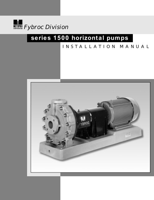
<strong>Fybroc</strong> <strong>Division</strong><strong>series</strong> <strong>1500</strong> <strong>horizontal</strong> <strong>pumps</strong>INSTALLATION MANUAL
INDEXPagePage<strong>Fybroc</strong> Warranty 3 Assembly/Disassembly Procedures 10Installation Instructions 4 General 10Location 4 Disassembly 10Foundation 4 Power-frame Disassembly 11Initial Alignment 4 Power-frame Assembly 12Piping the Pump 5 Pump End Assembly 13Suction Piping 5 John Crane Type 8B2 13Discharge Piping 5 John Crane Type 8-1T 14Ancillary Piping 5 John Crane Type 8-D 14Electrical Connections 6 Packed Stuffing Box 15Rotation 6 Impeller Adjustment 16Alignment and Coupling Installation 6 Installation Instructions Wood’s Couplings 17Start-up and Operating Procedures 7 Operational Start-up Checklist 19Lubrication 7 Sectional Drawings 20Oil Bath Lubrication 7 <strong>1500</strong> Group I 20Re-Greasable Bearings 7 <strong>1500</strong> Group II 21Greased for Life Bearings 7 <strong>1500</strong> Group III 22Seal Flushing 7 Typical Mechanical Seal Installations 23Mechanical Seals 7 Product Flush 23Packed Stuffing Box 7 External Flush 24Priming 7 Mechanical Seal Piping/Flow Requirements 25Starting 7 Single Mechanical Seal 25Operational Check List 8 Double Mechanical Seal 26Maintenance 8 Notes 27Pump 8 Notes 28Oil Bath Lubrication 8 Notes 29Re-Greasable Bearings 8Greased for Life Bearings 8Motor 8Trouble Check List 9ORDERING REPLACEMENT PARTSFor future reference fill in the following information from the pump nameplate.This will be necessary to ensure accuracy when ordering replacement parts.ModelSizeSerial NumberImpeller Diameter InstalledSeal TypeMaterial of Construction
<strong>Fybroc</strong> <strong>Division</strong>WARRANTYPERFORMANCEGUARANTEEACCEPTANCETESTSPERFORMANCEPRESENTATIONSFIELD TESTINGALL WARRANTIESFYBROC <strong>pumps</strong> are warranted by the Company, insofar as the same are of its own manufacture,against defects in materials and workmanship under proper and normal use andservice, for a period of one year from the date of original shipment from the factory.FYBROC’s obligation is limited, however, to furnishing without charge, F.O.B. its factory,new parts to replace any similar parts of its own manufacture so proving defective withinsaid period, provided the Buyer has given FYBROC immediate written notice upon discoveryof such defect. No allowance will be made for labor charges. FYBROC shall have theoption of requiring the return of the defective material, transportation prepaid, to establishthe claim.FYBROC makes no warranty or guarantee whatsoever, either express or implied, of primemover, starting equipment, electrical apparatus, parts or material not manufactured by<strong>Fybroc</strong>, except to the extent that warranty is made by the manufacturer of such equipmentand material.FYBROC assumes no liability for damages or delays caused by defective material, and noallowance will be made for local repair bills or expenses without the prior written approvalor authority of FYBROC.Under no circumstances will FYBROC be liable for indirect, special or consequential loss ordamage of any kind and the Buyer assumes all liability for the consequences of its use ormisuse by the by the Buyer, his employees, or others.Is at the specified point of rating only and will not cover performance under conditions varyingtherefrom, nor for sustained performance over any period of time.If required, shall be conducted in accordance with the practices as set forth in the HydraulicInstitute Standards. The expense of any such tests shall be borne by the buyer.Are based on shop laboratory tests with cold water as outlined in the Hydraulic InstituteStandards.Due to the inaccuracies of field testing, the results of any such tests conducted by or forthe Buyer shall be interpreted as being only indicative of the actual field performance of thepump. No equipment will be furnished on the basis of acceptance by results of field tests.If the buyer, after such a test, questions the performance of the pump, he may at his optionrequest a test to establish the performance. Such tests will be conducted in accordancewith the above paragraph entitled “Acceptance Tests.”Are void if -a. Pipe strains are the cause of damage.b. Pump handles liquids other than those specified in detail.c. NPSH lower than required by pump impeller.d. Operating speed is higher than specified.e. Improper field installation.To combat corrosion, abrasion, erosion, or pumping solids, foreign objects, or pumpingliquids at elevated temperature, any such recommendations will be based on the bestavailable experience of FYBROC and the supplier of the material and industry, BUT WILLNOT CONSTITUTE A GUARANTEE AGAINST THESE EFFECTS.RECOMMENDATIONSFOR SPECIALMATERIALSThe foregoing warranty is made in lieu of all other warranties guarantees, obligations orliabilities, expressed or implied, by FYBROC or its representatives. All statutory or impliedwarranties, other than of title, are hereby expressly negated and excluded.All illustrations and provisions in specifications are descriptive and are not intended aswarranties. Penalty of any kind are not acceptable unless approved in writing by an officerof Met-Pro Corporation.3
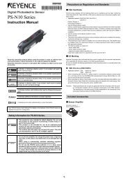
INSTALLATION HORIZONTAL PUMPSLOCATIONThe pump should ideally be placed as close aspossible to the liquid supply source. Allow sufficientspace on the sides and overhead to permitinspection and maintenance work to be performed.FOUNDATIONThe foundation for the pump should be level, providerigid support and alignment of pump andmotor. It should also be of sufficient mass todampen any vibrations developed. Typically this isaccomplished by installing and grouting a <strong>Fybroc</strong>baseplate on a concrete foundation.Foundation bolts of the proper size should beimbedded in the concrete with anti-rotation lugs,located by a drawing or template. (See Figure 1and Table 1 below for bolt-size and locations). Apipe sleeve larger than the bolt should be used toallow enough lateral movement for final positioningof the bolts. (See Figure 2 below). Levelingwedges or shims should be placed under the sidesof the baseplate to level the unit and the foundationbolts slightly tightened.A wood form can now be built around the edge ofthe baseplate to contain the grout. The top of therough concrete foundation should be wetted downprior to grouting. A good grade of non-shrinkinggrout can now be poured through the fill hole onthe top of the fiberglass baseplate. On baseplateswith raised motor mounting sections, a shortlength of pipe or tubing can be fitted into the grouthole to allow the grout to completely fill the raisedsection to the baseplate up to the vent hole in theraised section, as shown in figure below. Once thegrout starts to set, the extension can be removed,leaving the grout level with the top of the baseplate.Once the grout has fully hardened, usuallyabout 48 hours after pouring, the foundation boltscan be fully tightened.FIGURE 2FIGURE 1TABLE 1Base A B C D E F G BoltPlateSize1T 35 32 1/2 8 10 2 5/8 3 3/8 3/4 1/22T 39 36 1/2 9 12 2 7/8 2 7/8 3/4 1/21 45 42 1/2 9 12 3 3/4 2 3/4 3/4 1/22 52 49 1/2 12 15 3 3/4 3 3/4 3/4 1/23 58 55 1/2 15 18 4 4 1 3/44 60 57 1/2 15 18 4 4 1 3/45 68 65 1/2 19 22 4 1/2 4 1/2 1 3/46 80 77 1/2 19 22 4 1/2 4 1/2 1 3/44INITIAL ALIGNMENTAlignment of the pump and driver through theflexible coupling is of extreme importance fortrouble-free mechanical operation. If the driver wasmounted at the factory, the unit was rough alignedprior to shipment. However, in transit andsubsequent handling, this factory alignment waspossibly disturbed, and it is recommended thealignment be checked.The following steps are suggested to establish theinitial alignment of the pump unit:1) Be sure the foundation bolts are tight.2) Be sure the casing and frame feet are tight.3) Use shims under the driver feet to establishparallel and angular alignment of pump andmotor shafts.
PIPING THE PUMPPiping must not be connected to the pump untilbase, pump, and driver are initially aligned, failureto do so may result in the inability to attain properalignment later.All flanged connections to the pump should be fullflat face with full contact gaskets. Raised faceflanges or partial contact gaskets should not beused as excessive strains can be applied to thepump flanges upon tightening.The pump has been designed with all necessarystrength factors for long, reliable service life.However, due to the composite construction, caremust be taken during installation to avoid unnecessarypipe strain. If severe piping strains are to beencountered, flexible connections are recommendedin the suction and discharge pipe lines. Whenlined piping is used, flange alignment should becarefully checked. Spacer ring gaskets are recommendedto assure parallel alignment of pipe andpump flanges. The following flange bolt torquevalues should be used:Flange SizeBolt Torque1 1/2” 9-12 ft-lbs2” 18-24 ft-lbs3” 23-30 ft-lbs4” 27-36 ft-lbs6” & Larger 35-50 ft-lbsAll piping must be supported independently of thepump. The piping should always line up naturallywith the pump flanges. Never draw the piping to thesuction or discharge flanges of the pump. Outsideinstallations should be properly compensated forchanges in ambient temperatures. Refer to pipemanufacturers standards for proper installation.Omission of this could result in severe straintransmitted to the pump flanges.The piping should be as short and direct as possible.Avoid all unnecessary elbows, bends and fittings, asthey increase friction losses in the piping.SUCTION PIPINGA) To minimize friction loss, the length of the suctionpipe (from process to pump inlet) should be asshort as possible. It is important that NPSHavailable to the pump is greater than theNPSH required by the pump, long suction runsgreatly affect NPSH and should be consideredcarefully. See pump performance curve forNPSH requirements.B) The diameter of the suction pipe should be aslarge as the pump suction. If long suction runsare encountered, the suction pipe diametershould be increased to reduce the NPSHrequired.C) <strong>Inc</strong>reasers or reducers, if used, should beeccentric and installed with the eccentric sideon the bottom of the pipe to prevent air traps.D) Elbows, fittings, valves or expansion jointsshould be avoided at the suction flange. Allowa straight run of at least 10 pipe diameters intothe suction of the pump.E) If a valve is to be installed in the suction piping,only full flow valves offering a minimumflow disturbance should be used (ball, plugtypes). These valves should be for shut-offonly when the pump is not running, and not forthrottling or controlling flow. Centrifugal <strong>pumps</strong>should never be throttled on the suction side.F) Provisions for a suction pressure gauge shouldbe included.DISCHARGE PIPINGA) Installation of a valve in the discharge line thatcan be used as a block for inspection andmaintenance is recommended. It should be ofa design to allow throttling or flow control.B) The diameter of the discharge pipe should beas large or larger than the pump discharge.C) Provision for a discharge pressure gaugeshould be included.ANCILLARY PIPINGA) The diameter of the ancillary or seal pipingshould be large enough to meet the seal flushingrequirements. Typically this is 1/4-1/2 GPMat a pressure of 15-25 PSI above the suctionpressure for most mechanical seals. Refer topages 25 and 26 for recommended seal flushflow rates and piping installations.5
B) Where the ancillary piping is connected to thepump only plastic fittings shall be used.WARNING: FAILURE TO USE PLASTICFITTINGS MAY RESULT IN DAMAGE TOTHE PUMP.C) Many modern flush systems incorporate electricallyactuated solenoid valves to conserveand control the flow of flush liquids, ensure thatthe flush liquid is flowing to the seal before thepump is started.D) On double seal arrangements with flush in andflush out connections, flow control valvesshould be installed in the flush out or downstreamside.The pump shaft should turn freely by hand afterthe piping has been connected to the pump. Thisis to insure that the piping has not caused bindingin the pump. If binding occurs, check alignmentand realign if necessary.ELECTRICAL CONNECTIONSA) All electrical work done to the unit should bedone by a qualified electrician. All local, state andfederal electrical codes should be adhered to.B) Before any motor wiring is done, make suremotor shaft is disengaged from pump shaft byremoving coupling sleeve.ROTATIONAll <strong>pumps</strong> operate in a clockwise direction whenviewed from the coupling end of the pump shaft,(see direction arrow on the pump bearing-frame).Connect electric motor to power supply and jogmotor to check rotation. If motor is operating inwrong direction, reverse leads and recheck. Withcorrect motor rotation established, reinstall couplingsleeve and coupling guard.WARNING: DO NOT START PUMP WITH COU-PLING SLEEVE ENGAGED UNTIL BEARINGFRAME HAS BEEN PROPERLY LUBRICATEDAND MECHANICAL SEAL IS PROPERLYFLUSHED.ALIGNMENT AND COUPLING INSTALLATIONAccurate alignment of the pump and driver is ofextreme importance for long term trouble-freemechanical operation.Closer alignment will result in reduced vibrationlevels and longer expected bearing life. Most<strong>Fybroc</strong> <strong>pumps</strong> are supplied with Wood’s flexiblecouplings as standard equipment, for specificinstallation instructions refer to page 17. If adifferent coupling is supplied, specific installationinstructions will be included with the pump.WARNING: DO NOT START <strong>1500</strong> SERIESPUMPS WITH COUPLING SLEEVEINSTALLED UNTIL MOTOR ROTATION HASBEEN DETERMINED, AS DAMAGE COULDRESULT FROM REVERSE ROTATION.C) Wire motor according to motor manufacturersinstructions. Ensure that all connections andcovers are tight and that proper sized wire andswitch-gear are used.6
LUBRICATIONOil Bath LubricationWhen the power-frame is the oil bath lubrication type(standard construction), the bearing frame housing isNOT lubricated at the <strong>Fybroc</strong> factory. LubricantMUST be added to the bearing frame prior to <strong>pumps</strong>tart-up.A high-quality turbine type non-detergent oil, with rustand oxidation inhibitors should be used. For themajority of operating conditions, the oil temperatureshould run between 50°F (10°C) and 180°F(82°C). Inthis range, an oil of 300 SSU viscosity at 100°F(38°C), (approximately SAE-20) should be used.Remove the oil fill plug (Item 19) and fill the bearingframewith oil through the oil fill port. Add oil until theoil level is centered in the sight glass (Item 19G).There is an arrow in the casting to mark the center ofthe sight glass.WARNING: DO NOT FILL BEARING FRAMETHROUGH THE BREATHER CONNECTION AS OVERFILLING IS POSSIBLE, RESULTING IN OIL LEAKAGEAND EXCESSIVE BEARING TEMPERATURES.Approximate Bearing Frame Oil Capacity:Group I – 3/4 pintGroup II – 2 1/2 pintsGroup III – 6 pintsSTART-UP AND OPERATING PROCEDURESflush liquid must be supplied to the seal prior to starting.Proper flow for external flushing will vary from1/4 to 1/2 GPM at a pressure of 15 to 25 PSI abovethe stuffing box pressure.Packed Stuffing BoxThis method of sealing the pump requires an externalflush line for the intake of flush liquid. The flush linemust supply liquid to the packing prior to operation.The packing gland must be adjusted at start-up of thepump for proper operation. When the pump is putinto operation, the gland should be considerablyloose. After the pump is operating, the gland shouldbe slowly tightened to reduce the amount of leakage.Each time the packing is tightened the amount offlush liquid will decrease, however as the packingwarms up it will swell slowing the flow of flush liquideven more. A slight flow of liquid from the stuffing boxis necessary to provide lubrication and cooling(approximately 40 - 60 drops per minute after thepacking has run in).WARNING: PACKING CONTAINING FLUOROCAR-BON COMPOUNDS MUST BE CONSTANTLYCHECKED WHEN FIRST STARTED AS IT HAS ATENDENCY TO RAPIDLY EXPAND FROM TEM-PERATURE CHANGES RESULTING IN BLOCK-AGE OF THE FLUSH LIQUID, FAILURE TO DO SOMAY RESULT IN DAMAGE TO THE PUMP.Re-Greasable BearingsWhen the power-frame assembly is there-greasable bearing type, the bearings areinitially lubricated at the factory.Greased For Life BearingsWhen the power-frame assembly is supplied withgreased for life bearings there is no action required.SEAL FLUSHINGMechanical SealDo not operate the pump without liquid to themechanical seal. Depending on the flush arrangementof the pump, the fluid to the seal may be pipedfrom the pump discharge externally or internally, orfrom an external clean source. If the pump is fittedwith an internal or bypass flush arrangement, thenthe pump must be flooded with liquid prior to startingto ensure that the mechanical seal is lubricated. If thepump is equipped for an external flush system, then7PRIMINGSuction valve must be fully open. The pump casingand suction pipe must always be full of liquid beforethe pump is started. Centerline discharge designs areself-venting therefore the discharge valve should beopened to release any air trapped in the pump andthen left slightly open at start-up.STARTINGPrior to starting, turn pump shaft by hand to besure rotating elements are free. If it rubs or binds:A) Check alignment.B) Check for piping strains on casing flanges,or other loads on casing.C) Check impeller clearance. (See impelleradjustment).With pump rotating elements free, replacecoupling guard.
Prior to starting pump recheck installation procedureswith the operational start-up checklist foundon page 19 of this manual.Start pump and bring up to speed, open dischargevalve to the rated flow.WARNING: DO NOT RUN PUMP WITH A CLOSEDDISCHARGE VALVE AS THE LIQUID IN THEPUMP WILL RAPIDLY INCREASE IN TEMPERA-TURE, POSSIBLY CAUSING DAMAGE TO PUMP.Check flush water to mechanical seal, if not lubricatedfrom the pump discharge.Check oil levels in the bearing frame.If the pump is provided with packing, the glandshould be adjusted (while running) to allow leakageof approximately 60 drops per minute.EXERCISE EXTREME CAUTION.OPERATIONAL CHECK LISTA) Periodically check stuffing box for leakage withpacking, and no leakage with mechanicalseals.B) Periodically check lubrication to the pump anddriver bearings.C) Periodically check for excessive vibrations andoil temperatures. Correct if necessary.MAINTENANCE<strong>Fybroc</strong> <strong>pumps</strong> are designed for a long service life.The only scheduled maintenance items are thelubrication intervals for the pump and motor.Please refer to the lubrication procedures given inthe start-up section.PUMPOil Bath LubricationThe frequency with which the oil in the powerframeshould be changed depends greatly on theoperating temperature and the cleanliness of theenvironment. For power-frames running at approximately122°F (50°C), typically the lower speed<strong>pumps</strong>, the oil should be changed once a year. Forpower-frames running at approximately 167°F(75°C) the oil should be changed every sixmonths. If the environment is hostile, the lubricationintervals should be reduced.Re-Greasable BearingsThe frequency with which the grease in the powerframeshould be changed depends greatly on theoperating time and the cleanliness of the environment.For power-frames running at 2900-3500 rpmthe bearings should be re-lubricated every 5,000hrs, for all other speeds every 10,000 hrs.Before greasing, be sure fittings are clean and freefrom dirt. Remove the 1/8" grease relief plugs forthe front and rear bearings. Using a standardgrease-gun inject grease into the bearing using thegrease fittings until grease comes out of the bleedholes. Allow the pump to operate approximately 2hours before replacing the pipe-plugs, this willallow any excess grease to purge itself.WARNING: FAILURE TO REMOVE THE PURGEPLUGS WHEN FILLING THE BEARINGS WITHGREASE MAY RESULT IN DAMAGE TO THEBEARING SEALS.Greased For Life BearingsGreased for life bearings require no maintenance.MOTORThe motor re-lubrication intervals are greatly influencedby the environment it is in and the length oftime it runs. Refer to the following chart for typicalre-lubrication values for motors. Standard duty iswhen the motor is operated eight hours a day andthe environment is free from dust. Severe duty iswhen the motor runs twenty-four hours per daywith exposure to dirt and dust.Sync RPM Motor Frame Type of ServiceRange Range Standard Duty Severe Duty143T - 256T 5 Yrs 3 Yrs3600 284T - 286T 1 Yr 4 Mos324T - 365T 9 Mos 3 Mos143T - 256T 7 Yrs 3 Yrs1800284 - 326T 4 Yrs 1.5 Yrs364T - 365T 2.5 Yrs 10 Mos404T - 447T 2 Yrs 8 Mos143T - 256T 7 Yrs 3 Yrs1200 284T - 326T 4 Yrs 1.5 Yrs364T - 447T 3 Yrs 1 Yr8
Instructions For Lubricating MotorsBefore greasing, be sure fittings are clean and freefrom dirt. Remove grease relief plug or plate andusing a low pressure grease gun pump in therequired grease. Do not over-grease. After relubricatingallow motor to run for an hour beforereplacing relief hardware.TROUBLE CHECK LISTRefer to the following diagnostic section ifhydraulic problems are encountered in the pumpoperation.PROBLEM:CHECK:Pump runs but intermittently<strong>pumps</strong> liquid.Suction line leaks.Stuffing box leakage of air.Air pocket in suction line.Insufficient NPSH.Air or gases in liquid.PROBLEM:CHECK:Not enough liquid, or no liquiddelivered.Suction pipe and /or pumpcasing not filled with liquid.Speed too low.(Result, reduced TDH).Suction lift too high or insufficientNPSHA. (Cavitation).Impeller or suction pipe pluggedwith solids.PROBLEM:CHECK:Pump takes to much power.Speed too high.Head lower than rating; pumpingbeyond design point.Liquid heavier than specified;check viscosity and specificgravity.Mechanical defects (Bent shaft,rotating element binds, packingtoo tight, misalignment).Wrong rotation.(Result, reduced TDH).Air pockets in suction line orair leaking in through packingbox area.Suction strainer plugged, ifused in suction line.PROBLEM:Not enough pressure.CHECK:Speed too low.Air or gases in the liquid.Check impeller diameter.Mechanical defects(impeller clearance too great;impeller damaged).Wrong rotation.Pressure gauge in a poor location.9
If the mechanical seal is a double inside seal,remove the four bolts and washers (Item 17C,17E) securing the gland (Item 17) to the cover(Item 11) and remove the gland. Be sure the setscrews are loose and pull the rotary seal assemblyoff the sleeve using a twisting motion as it isremoved. The integral sleeved impeller (Item 2)can be removed from the cover. Next remove thestationary seal faces from the gland and cover bygently pressing them out using your thumbs. Thecarbon and ceramic elements of the seal shouldbe handled carefully to prevent chipping orscratching.If packing is supplied with the pump then firstremove the upper four nuts and washers securingthe gland and remove the gland. Next remove thelower four nuts and washers and remove the stuffingbox extension. Now remove the packing ringsand lantern ring, keeping them in order to preservethe location of the lantern ring. The gland studscan now be removed from the cover.POWER-FRAME DISASSEMBLYAfter removing the pump casing, impeller, andcover assembly from the power-frame, proceedwith the following:1) Drain oil from the power-frame assembly byremoving the drain plug (Item 19A). Collect oilinto a suitable container.2) Remove the deflector, if the pump utilizes oilseals, (Item 40) by sliding off the shaft.3) Remove only the adjusting screws (Item 33A)that secure the bearing housing (Item 33) tothe power-frame (Item 19).4) The shaft assembly is now ready for removal.Slowly and evenly turn the remaining adjustingjacking screws (Item 33A) until the outboardbearing housing (Item 33) clears the frame (Item19). This will require the use of shims or barstockbeing placed between the adjusting jackingscrews and bearing frame. The adjusting jackingscrews by themselves are not long enough toeffect complete clearance from the frame. Becareful when removing the shaft assembly not todamage the impeller threads on the end of theshaft by contacting the cast-iron. You now shouldbe holding the shaft, bearings, and outboardbearing housing assembly.5) Remove the shaft and bearing assembly fromthe outboard bearing housing, by removing theinternal retaining ring (Item 18A). Lightly tapthe outboard shaft end with a soft-headedmallet until the outboard bearing clears thebearing housing (Item 33).6) Remove the outboard bearing (Item 18) fromthe shaft by disengaging the tang on the lockwasher(Item 69) from the lock-nut (Item 22),and then remove the lock-nut with a bearinglock-nut wrench or by tapping the groove in thelock-nut with a hammer and drift. The bearingcan now be pressed from the shaft.7) Remove the internal retaining ring (Item 18A)from the shaft.8) Remove the inboard bearing (Item 16) bypressing from the shaft. Protect the impellerthreads and coupling end of the shaft fromdamage when pressing bearings off the shaft.9A) If the bearing frame is provided with labyrinthtype oil seals, and they are still in good conditionthey can remain in the bearing frame andbearing housing. If replacement is necessarythey can be pressed out of their respectivehousings.9B) If the bearing frame is provided with lip type oilseals, remove the oil seals (Items 47 & 49) fromthe outboard bearing housing and from thepower-frame. These seals are removed by lightlytapping with a soft-headed mallet. Note: theseseals should not be reused after disassembly.10) Remove the o-ring seal (Item 33B) from thebearing housing.11) If separate, remove the bearing frame adapterscrews (Item 71A) and remove the adapter(Item 71). Remove the casing jack-screws(Item 19D) from the adapter.12) If separate, remove the frame-leg screws(Item 19F) and remove the frame-leg(Item 19E).13) Remove the sight-glass, breather and plugs(Items 19A, 19B, 19C, 19G and 19H) fromtheir respective locations.11
POWER-FRAME ASSEMBLY1) Clean and visually inspect all parts prior toreassembly. Particularly note condition ofshaft surfaces and housing bores where oilseals contact.2) Evenly heat bearings up to 167°F (75°C)above room temperature, approximately 239°F(115°C). Do not exceed 257°F (125°C) asdamage to the bearings may occur.WARNING: SINCE THE SHAFT IS TYPICALLYMADE OF STAINLESS STEEL, PRESSINGTHE BEARINGS ON THE SHAFT MAYRESULT IN DAMAGE TO THE SHAFT.3) Note orientation of bearings before installingon shaft:Outboard Bearing (coupling end) – If bearingcontains ball filling slots, the slots should befacing the coupling (key-way) end of shaft. Ifthe bearing has a single shield, the shieldfaces toward the coupling end of the shaft. Ifthe pump is provided with re-greasable bearings,the bearing grease shield should facethe impeller (threaded) end of shaft.Inboard Bearing (impeller end) – If bearingcontains ball filling slots, the slots should befacing the coupling (key-way) end of shaft. Ifthe bearing has a single shield, the shieldfaces toward the threaded end of the shaft. Ifthe pump is provided with re-greasable bearings,the bearing grease shield should facethe coupling (key-way) end of shaft.4) Install the outboard bearing (Item 18) on theshaft (Item 6) by sliding it over the key-wayend of the shaft until it is seated squarelyagainst the shaft shoulder.5) Place the retaining ring (Item 18A) over theshaft before installing the inboard bearing, asthis is impossible to install later.6) Install the inboard bearing (Item 16) on theshaft (Item 6) by sliding it over the threadedend of the shaft until it is seated squarelyagainst the shaft shoulder.7) Install the lock-washer (Item 69) and lock-nut(Item 22) against the outboard bearing andthen tighten the lock-nut with a bearing locknutwrench or by tapping the groove in thelock-nut with a hammer and drift. The lock-nutcan then be secured by bending the tang onthe lock-washer into the groove on the locknut.Be careful not to mar the oil seal surfacesof the shaft which are in close proximity to thebearings and lock-nut.8) Install the o-ring seal (Item 33B) on thebearing housing.9) If the bearing frame is provided with labyrinthtype oil seals, lubricate the seal o-rings andpress fit the labyrinth seals (Items 47 & 49) intothe bearing housing and bearing frame bores.10) Install the shaft and bearing assembly into thebearing housing (Item 33), by first lubricatingthe bore with some oil and then sliding in theshaft assembly. Lightly tap the bearing housingwith a soft-headed mallet until the outboardbearing clears the retaining ring groove. Usingsnap-ring pliers install the retaining ring (Item18A) with the opening in the ring lining up withthe oil return slot in the bearing housing.11) If the bearing frame is provided with lip type oilseals, install the outboard oil seal (Item 49) intothe bearing housing. Lubricate the ID of the sealand place sealant around the OD of the seal.Carefully place the oil-seal over the shaft watchingout for sharp edges such as on key-ways andplace up against the bore. Seat the oil-seal inplace with a soft-faced tool applying force evenlyaround the outer edge to avoid cocking the seal.Wipe off any excess sealant.12) The shaft assembly is now ready for installation.Ensure that the power-frame is free of contaminantsand then lubricate the bores in the powerframewith oil to ease installation. Line up theshaft assembly so the oil-drain slot in the bearinghousing is facing down and slide the shaft assemblyinto the power-frame as far as it will go byhand. Check to be sure the assembly is going instraight. Lightly tap the key-way end of the shaftto assure the shaft is in its forward most position.Be careful not to pinch the bearing housing o-ringseal (Item 33B) on the power-frame, or damagethe o-ring in the labyrinth oil seal.13) Install the adjusting screws (Item 33A). Ifscrews are of different length, the longerscrews thread into the power-frame.14) Install the inboard lip type oil seal, if required(Item 47) into the power-frame. First ensurethat the bore and shaft diameter are cleanand free of scratches or grooves. Lubricate12
the ID of the seal and place sealant aroundthe OD of the seal. Carefully place the oil-sealover the shaft watching out for sharp edges suchas on impeller threads and place up against thebore. Then seat the oil-seal in place with a softfacedtool applying force evenly around the outeredge to avoid cocking the seal. Wipe off anyexcess sealant.15) Install the deflector (Item 40), if bearing frameis provided with lip type oil seals, by sliding onthe shaft.16) Install sight-glass, breather and plugs (Items19A, 19B, 19C, 19G and 19H) in their respectivelocations.17) If separate, install the frame-leg (Item 19E) andsecure with frame-leg screws (Item 19F), torqueto 25 ft-lbs.18) If separate, install the bearing frame adapter(Item 71). Ensure that the adapter is seatedsquarely on the power-frame before tighteningadapter screws, this may require some sandingof the paint on the pilot diameters. Secure withadapter screws (Item 71A), torque to 25 ft-lbs.19) Install the casing jack-screws (Item 19D), ensurethat the screws do not extend past the cast ironcover adapter, as damage could result to the pump.CAUTION: Prior to starting the pump, re-lubricatethe bearing frame.PUMP END ASSEMBLY1) Inspect casing, cover and impeller for anydamage and make sure all sealing surfaces arefree of dirt and scratches. If pump is equippedwith an internal seal flush, make sure cover flushhole is clear.2) Use the adjusting screws (Item 33A) to adjustthe bearing housing (Item 33) to its forward mostposition and then lightly coat the shaft threadswith an anti-seize compound.3) The <strong>Fybroc</strong> pump, as standard, is equipped witha single outside seal with stationary seal faceand rotating compression unit, or a double insideseal with stationary seal faces and rotatingdouble seal compression unit. The followinginstallation instructions are based on these sealtypes. When other types of seals are used,please refer to the manufacturer’s installationdata. Determine the type of seal being used andrefer to the following sections.13SINGLE OUTSIDE SEAL INSTALLATIONJOHN CRANE TYPE 8B21) Remove the mechanical seal from its packaging,inspect for any damage, and keep seal faces cleanand free from contaminants during installation.DO NOT GREASE OR LUBRICATE SEAL FACES.2) Install the inboard stationary seal gasket and thestationary seal insert into their bores on thepump cover. Then place the outboard stationarygasket over the stationary insert. Next place theseal gland over the stationary insert and gaskets,making sure that all the gaskets have beeninstalled properly before securing the gland bolts.Be sure that the gland pilot is properly engaged,and draw up the gland bolts evenly, cross staggeringadjustment of the bolts. Proper gland boltadjustment is especially important where clampstyle inserts are used. The gland bolts should betorqued to a maximum of 10 Ft/Lbs.3) Lightly coat the impeller sleeve with a suitablelubricant. Carefully slide impeller sleeve throughthe cover, being careful not to chip the stationarysealing face.3A) For separate shaft sleeve installation, positionthe cover over the impeller and insert the sleevethrough the mechanical seal stationary insertuntil the hooked end of the sleeve rests on theimpeller hub.4) Lubricate the rotary unit o-ring with a suitablelubricant. Then engage the rotary assembly overthe impeller sleeve. Use a slight twisting motionas the rotary unit is slid down the impeller sleeveuntil it touches the stationary sealing face. Donot tighten set screws or remove setting clips.5) Mount the impeller, cover and seal assembly ontothe power-frame, making sure the impellerthreads are firmly bottomed on the shaft threads.5A) For separate shaft sleeve installation, slide thesleeve and seal assembly over the shaft until thehooked end of the sleeve bottoms on the shaftshoulder. Install and clamp cover in position.Insert impeller o-ring (Item 2B) in the groove onthe impeller hub and thread impeller onto shaftinsuring impeller hub, sleeve hook and shaftshoulder are firmly bottomed.6) At this stage check to be sure the impellerthreads are properly seated on the shaft threads.There should be clearance between the coverface and the back of the impeller. If there is no
clearance, adjust the shaft forward with theadjusting screws (Item 33A) and reseat theimpeller. (See impeller adjustment section.)7) With the impeller threads firmly seated, adjustthe impeller towards the cover (see impelleradjustment section) until the back of the impellerjust touches the cover face.8) Install the cover o-ring (Item 73) and casing.Adjust the axial impeller clearance to the specifiedvalue in the impeller adjustment section.9) Slide the seal rotary unit until it touches the sealstationary face with a slight twisting motion.Tighten the rotary set screws and remove theassembly clips. No further seal adjustment isnecessary.10) Make appropriate piping connections to the sealassembly.DOUBLE SEAL INSTALLATIONJOHN CRANE TYPE 8-1T1) Remove the mechanical seal from its packaging,inspect for any damage, keep seal faces cleanand free from contaminants during installation.DO NOT GREASE OR LUBRICATE SEAL FACES.2) Lightly lubricate the inboard stationary inserto-ring and cover bore with a suitable lubricantand then install the inboard stationary insert intothe pump cover bore.3) Lightly lubricate the outboard stationary, inserto-ring and gland bore, and install the outboardstationary into the gland bore.4) Lightly coat the impeller sleeve with a suitablelubricant. Carefully slide impeller sleeve throughthe cover, being careful not to chip the stationarysealing face.4A) For separate shaft sleeve installation, positionthe cover over the impeller and insert the sleevethrough the mechanical seal stationary insertuntil the hooked end of the sleeve rests on theimpeller hub.5) Lubricate the rotary unit o-rings with a suitablelubricant. Then engage the rotary assembly overthe impeller sleeve. Use a slight twisting motionas the rotary unit is slid down the impeller sleeveuntil it touches the stationary sealing face. Do nottighten set screws.6) Install the gland o-ring into its groove on thegland. Then place the gland over the rotatingseal assembly, making sure the gland o-ring is inplace before securing the gland bolts. Be surethat the gland pilot is properly engaged, anddraw up the gland bolts evenly, cross staggeringadjustment of the bolts. The gland bolts shouldbe torqued to a maximum of 10 Ft/Lbs.7) Mount the impeller, cover and seal assembly ontothe power-frame, making sure the impellerthreads are firmly bottomed on the shaft threads.7A) For separate shaft sleeve installation, slide thesleeve, gland and cover assembly over the shaftuntil the hooked end of the sleeve bottoms onthe shaft shoulder. Clamp cover in position.Insert impeller o-ring (Item 2B) in the groove onthe impeller hub and thread impeller onto shaftinsuring impeller hub, sleeve hook, and shaftshoulder are firmly bottomed.8) At this stage check to be sure the impellerthreads are properly seated on the shaft threads.There should be clearance between the coverface and the back of the impeller. If there is noclearance, adjust the shaft forward with theadjusting screws (Item 33A) and reseat theimpeller. (See impeller adjustment section)9) With the impeller threads firmly seated, adjustthe impeller towards the cover (see impelleradjustment section) until the back of the impellerjust touches the cover face.10) Install the cover o-ring (Item 73) and casing.Adjust the axial impeller clearance to the specifiedvalue in the impeller adjustment section.11) Remove the pipe plug in the bottom of the gland.Center the set screws of the seal rotary unit inthe pipe plug hole and tighten. Replace pipeplug and make appropriate piping connections tothe seal assembly.DOUBLE SEAL INSTALLATIONJOHN CRANE TYPE 8-D1) Remove the mechanical seal from its packaging,inspect for any damage, keep seal faces cleanand free from contaminants during installation.DO NOT GREASE OR LUBRICATE SEAL FACES.2) Lightly lubricate the inboard stationary inserto-ring and cover bore and install the inboardstationary insert into the pump cover bore.3) Lightly lubricate the outboard stationary inserto-ring and gland bore and install the outboardstationary insert into the gland bore.14
4) Lightly coat the impeller sleeve with a suitablelubricant. Carefully slide impeller sleeve throughthe cover, being careful not to chip the stationarysealing face.NOTE: The John Crane 8-D is a friction drivetype of seal, the impeller sleeve and rotary unitshould be lubricated with a soapy watersolution to ease installation without reducing thefrictional drive of the rotary unit.4A) For separate shaft sleeve installation, positionthe cover over the impeller and insert the sleevethrough the mechanical seal stationary insertuntil the hooked end of the sleeve rests on theimpeller hub.5) Lubricate the rotary unit o-rings with a suitablelubricant. Then engage the rotary assembly overthe impeller sleeve. Use a slight twisting motionas the rotary unit is slid down the impeller sleeveuntil it touches the stationary sealing face.6) Install the gland o-ring into its groove on thegland. Then place the gland over the rotatingseal assembly, making sure the gland o-ring is inplace before securing the gland bolts. Be surethat the gland pilot is properly engaged, anddraw up the gland bolts evenly, cross staggeringadjustment of the bolts. The gland bolts shouldbe torqued to a maximum of 10 Ft/Lbs.7) Mount the impeller, cover and seal assemblyonto the power-frame, making sure the impellerthreads are firmly bottomed on the shaft threads.7A) For separate shaft sleeve installation, slide thesleeve, gland, and cover assembly over theshaft until the hooked end of the sleevebottoms on the shaft shoulder. Clamp cover inposition. Insert impeller o-ring (Item 2B) in thegroove on the impeller hub and thread impelleronto shaft insuring impeller hub, sleeve hook,and shaft shoulder are firmly bottomed.8) At this stage check to be sure the impellerthreads are properly seated on the shaft threads.There should be clearance between the coverface and the back of the impeller. If there is noclearance, adjust the shaft forward with theadjusting screws (Item 33A) and reseat theimpeller. (See impeller adjustment section)9) With the impeller threads firmly seated, adjustthe impeller towards the cover (see impelleradjustment section) until the back of the impellerjust touches the cover face.1510) Install the cover o-ring (Item 73) and casing.Adjust the axial impeller clearance to the specifiedvalue in the impeller adjustment section.11) The 8-D seal is self centering and requires noadjustment. Make appropriate piping connectionsto the seal assembly.PACKED STUFFING BOX1) Install the four gland studs into the cover andtighten to 10 ft-lbs.2) Install o-ring in stuffing box extension. Placeover gland studs and check that the stuffing boxextension is seated properly. Secure to coverwith gland nuts and washers, tighten to 10 ft-lbs.3) Place metallic shaft sleeve in cover bore, andinstall two packing rings into the stuffing boxextension. Install the lantern ring followed byremaining three packing rings.4) Check to make sure lantern ring is lined up withflush hole. Damage could result to packing andshaft sleeve if flush water is restricted.5) Install gland ring over gland studs and securewith gland nuts and washers. Hand-tighten thenuts for now. The nuts need to be adjusted whenthe pump is started up.6) Mount the cover assembly and sleeve onto thepower-frame.7) Clamp the cover in position and slide the shaftsleeve towards the bearing frame until it bottomson the shaft shoulder. Insert impeller o-ring inthe groove on the impeller hub and threadimpeller onto shaft insuring impeller hub, sleeveand shaft shoulder are firmly bottomed.8) At this stage check to be sure the impellerthreads are properly seated on the shaft threads.There should be clearance between the coverface and the back of the impeller. If there is noclearance, adjust the shaft forward with theadjusting screws (Item 33A) and reseat theimpeller. (See impeller adjustment section).9) With the impeller threads firmly seated, adjust theimpeller towards the cover (see impeller adjustmentsection) until the back of the impeller justtouches the cover face.10) Install the cover o-ring (Item 73) and casing.Adjust the axial impeller clearance to the specifiedvalue in the impeller adjustment section.11) Make appropriate flush piping connections to thestuffing box extension.
IMPELLER ADJUSTMENTThe <strong>horizontal</strong> <strong>1500</strong> <strong>series</strong> design permits adjustmentof the impeller clearance between the pumpcasing wall and the impeller face. The pumpimpeller is adjusted at the factory during assemblyand should not require further adjustment uponinstallation.Impeller adjustment will be required when a dropin head and/or capacity indicates a change inclearance, or when existing components of thepump are replaced. Refer to the following table forrecommended clearance when adjusting impelleron <strong>horizontal</strong> <strong>pumps</strong>.Impeller DiameterClearanceUp to 8" .015”8" to 10" .020”10" to 16" .025”A) Loosen set screws or other holding devices ifso provided on mechanical seals before adjustingimpeller to prevent seal face damage.B) Loosen the adjusting screws (Item 33A) evenly.C) Tighten up equally on the screws that threadinto the power-frame until you can feel theimpeller just starting to rub on the casing face.By rotating the shaft frequently by hand whiletaking up on the screws, you can determinewhen the impeller begins to bind.D) Back out the screws that thread into the powerframeuntil you can insert a feeler gauge undereach of the bolt heads to the recommendedclearance (See table above).E) Tighten the remaining adjusting jacking screwsuntil the gap left by the feeler gauge is gone.F) Check to be sure the shaft turns freely.G) Reset and tighten the mechanical seal per theseal manufacturers instructions.NOTE: Frequent impeller adjustments torestore hydraulic performance are an indicationof increased internal clearances. Excessiveclearance behind the impeller will result inexcessive thrust loads in high pressure <strong>pumps</strong>leading to reduced outboard bearing life.Replace worn parts.16
INSTALLATION INSTRUCTIONS WOOD’S COUPLINGSWARNING: DO NOT PROCEED WITH THECOUPLING INSTALLATION UNTIL THEDIRECTION OF MOTOR ROTATION HASBEEN ESTABLISHED TO BE CORRECT.FAILURE TO DO SO MAY RESULT INDAMAGE TO THE PUMP.1) Inspect all coupling components and removeany protective coatings or lubricants frombores, mating surfaces and fasteners. Removeany existing burrs, etc. from the shafts.2) Place four cap-screws with lock-washersthrough the holes in each spacer hub. Slideone spacer hub onto each shaft, usingsnug-fitting keys.3) If using a two-piece sleeve, assemble the twohalves together and hang the wire ring looselyin the groove next to the teeth.4) Position the sleeve between the two flanges.Be certain that the teeth on the sleeve are fullyseated in each flange.5) Place this assembly between the spacer hubs.Align the tapped holes in the flange with thecap-screws in one of the hubs. Hand tightenthese four cap-screws and visually inspect thegap between the hub and the flange to ensurethat the flange is seated properly. Tighten thefour cap-screws to their designated torquevalues, see table below.6) Rotate the other shaft until the cap-screws onthe other hub can be started into the tappedholes of the loose flange. Hand tighten thesefour cap-screws and visually inspect the gapbetween the hub and the flange to ensure thatthe flange is seated properly. Tighten the fourcap-screws to their designated torque values,see table below.7) Check to be certain that the sleeve is still fullyengaged in both flanges. Then slide the couplingassembly so that there is an equal lengthof shaft extending into each flange. Check thatthe shaft keys are fully engaged between theshaft and the hub before tightening the setscrewson both hubs. See the following tablefor torque values.TORQUE VALUES TYPE SC COUPLINGSCoupling Hub SizeCap-Screws (ft-lbs) Set-Screws (ft-lbs)3 — —4 5.5 135 4 136 9 137 9 138 18 239 31 2310 50 5011 75 5012 150 10013 150 16514 150 16516 150 1658) Check parallel alignment by placing a straightedgeacross the two couplingflanges and measuringthe maximum offset atvarious points around theperiphery of the couplingwithout rotating the coupling.If the maximum offsetexceeds the figure shown under “Parallel”in the following table, realign the shafts.9) Check angular alignment with a micrometeror caliper. Measure from the outside of oneflange to the outside of the other at intervalsaround the periphery ofthe coupling. Determinethe maximum and minimumdimensions withoutrotating the coupling. Thedifference between themaximum and minimummust not exceed the figure given under “Angular”in the following table . If a correction is necessary,be sure to recheck the parallel alignment.NOTE: KEEPING COUPLING MISALIGNMENTVALUES AS CLOSE TO ZERO AS POSSIBLEWILL EXTEND COUPLING LIFE ANDREDUCE VIBRATION LEVELS.17
MAXIMUM ALLOWABLE MISALIGNMENTSleeve Type JE & JN Type E & N Type HSize Parallel Angular Parallel Angular Parallel Angular3 .010 .035 — — — —4 .010 .043 — — — —5 .015 .056 .015 .056 — —6 .015 .070 .015 .070 .010 .0167 .020 .081 .020 .081 .012 .0208 .020 .094 .020 .094 .015 .0259 — — .025 .109 .017 .02810 — — .025 .128 .020 .03211 — — .032 .151 .022 .03712 — — .032 .175 .025 .04213 — — .040 .195 — —14 — — .045 .242 — —16 — — .062 .330 — —(Dimensions in <strong>Inc</strong>hes)10) If the coupling employs a two-piece sleevewith the wire ring, force the ring into itsgroove in the center of the sleeve. It may benecessary to pry the ring into position with ablunt screwdriver.11) Install the coupling guard over the couplingassembly and finger tighten the coupling guardcap-screws. Check for any contact betweenthe guard and the rotating assembly. Thentighten the coupling guard bolts to the torquevalues given on the side of the baseplate.WARNING: DO NOT OPERATE THE PUMPWITHOUT THE COUPLING GUARDINSTALLED PROPERLY AS COUPLINGSLEEVES CAN BE THROWN FROM THECOUPLING ASSEMBLY WITH SUBSTAN-TIAL FORCE IF THE COUPLING IS SUB-JECTED TO A SEVERE SHOCK LOAD.12) To remove the sleeve for inspection orreplacement, remove the eight cap-screwsfrom the spacer hubs. Then loosen the hubset-screws and slide the hubs back and dropthe sleeve and flange assembly out.WARNING: NEVER REPLACE A HYTRELSLEEVE WITH A RUBBER SLEEVE ASTHESE SLEEVES HAVE COMPLETELYDIFFERENT RATINGS AND INTERCHANG-ING THEM CAUSE DAMAGE TO THEEQUIPMENT.18
OPERATIONAL START-UP CHECKLISTFoundation level and baseplate grouted.Foundation bolts tight.Coupling aligned without sleeve.Motor and pump mounting bolts tight.Suction and discharge connections secure.Flush piping installed if required.Electrical connections secure and covered.Lubricate power-fame as required.Ensure that coupling sleeve is not installed.Jog motor/Check rotation.Turn pump shaft by hand, ensure that it does not bind.Check shaft alignment and install coupling sleeve.Ensure that all guards are in place.Ensure seal is properly flushed.Suction valve is open, Discharge valve is slightly open.Ensure that pump is primed.Start pump and open discharge valve to desired flow rate.Check flush water flow and pressure.Check oil level if so equipped.Check for excessive vibration and oil temperature.Check packing for leakage and mechanical seal for no leaks after run-in.19
<strong>1500</strong> SERIES GROUP 120
<strong>1500</strong> SERIES GROUP 221
<strong>1500</strong> SERIES GROUP 322
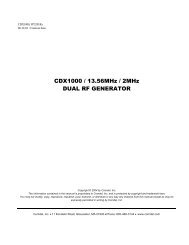
<strong>1500</strong> SERIES SEAL AND STUFFING BOX ARRANGEMENTSPRODUCT FLUSH:A portion of the pumped fluid is re-circulated throughthe stuffing box to provide lubrication and cooling tothe seal. Use plastic fittings only.23
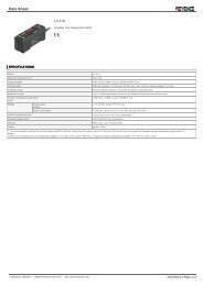
<strong>1500</strong> SERIES SEAL AND STUFFING BOX ARRANGEMENTSEXTERNAL FLUSH: An external source of clean fluid is required at thestuffing box to provide lubrication and cooling.Use plastic fittings only.24
FLUSH PIPING FOR SINGLE MECHANICAL SEALFLUSH FLOW RATE FOR SINGLE SEAL25
FLUSH PIPING FOR DOUBLE INSIDE MECHANICAL SEALFLUSH FLOW RATE FOR DOUBLE SEAL26
NOTES27
NOTES28
NOTES29
©COPYRIGHT 2000 MET-PRO CORPORATION, FYBROC DIVISION <strong>Fybroc</strong> <strong>Division</strong> ® IS A REGISTERED TRADEMARK OF MET-PRO CORPORATION 07-5326 300<strong>Fybroc</strong> <strong>Division</strong>700 Emlen Way, Telford, PA 18969TOLL-FREE: 1-800-FYBROC-1, Phone: (215) 723-8155, FAX: (215) 723-2197E-Mail: sales@fybroc.com, Web Site: www.fybroc.com