Fybroc Division series 1500 horizontal pumps - MHz Electronics, Inc
Fybroc Division series 1500 horizontal pumps - MHz Electronics, Inc
Fybroc Division series 1500 horizontal pumps - MHz Electronics, Inc

You also want an ePaper? Increase the reach of your titles
YUMPU automatically turns print PDFs into web optimized ePapers that Google loves.
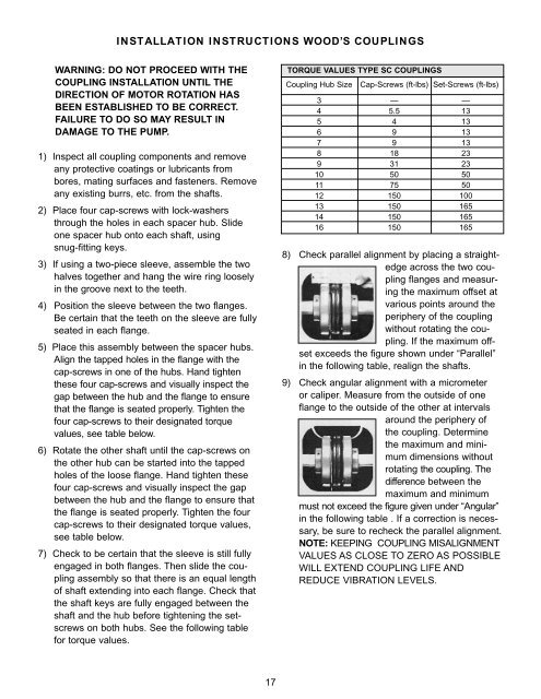
INSTALLATION INSTRUCTIONS WOOD’S COUPLINGSWARNING: DO NOT PROCEED WITH THECOUPLING INSTALLATION UNTIL THEDIRECTION OF MOTOR ROTATION HASBEEN ESTABLISHED TO BE CORRECT.FAILURE TO DO SO MAY RESULT INDAMAGE TO THE PUMP.1) Inspect all coupling components and removeany protective coatings or lubricants frombores, mating surfaces and fasteners. Removeany existing burrs, etc. from the shafts.2) Place four cap-screws with lock-washersthrough the holes in each spacer hub. Slideone spacer hub onto each shaft, usingsnug-fitting keys.3) If using a two-piece sleeve, assemble the twohalves together and hang the wire ring looselyin the groove next to the teeth.4) Position the sleeve between the two flanges.Be certain that the teeth on the sleeve are fullyseated in each flange.5) Place this assembly between the spacer hubs.Align the tapped holes in the flange with thecap-screws in one of the hubs. Hand tightenthese four cap-screws and visually inspect thegap between the hub and the flange to ensurethat the flange is seated properly. Tighten thefour cap-screws to their designated torquevalues, see table below.6) Rotate the other shaft until the cap-screws onthe other hub can be started into the tappedholes of the loose flange. Hand tighten thesefour cap-screws and visually inspect the gapbetween the hub and the flange to ensure thatthe flange is seated properly. Tighten the fourcap-screws to their designated torque values,see table below.7) Check to be certain that the sleeve is still fullyengaged in both flanges. Then slide the couplingassembly so that there is an equal lengthof shaft extending into each flange. Check thatthe shaft keys are fully engaged between theshaft and the hub before tightening the setscrewson both hubs. See the following tablefor torque values.TORQUE VALUES TYPE SC COUPLINGSCoupling Hub SizeCap-Screws (ft-lbs) Set-Screws (ft-lbs)3 — —4 5.5 135 4 136 9 137 9 138 18 239 31 2310 50 5011 75 5012 150 10013 150 16514 150 16516 150 1658) Check parallel alignment by placing a straightedgeacross the two couplingflanges and measuringthe maximum offset atvarious points around theperiphery of the couplingwithout rotating the coupling.If the maximum offsetexceeds the figure shown under “Parallel”in the following table, realign the shafts.9) Check angular alignment with a micrometeror caliper. Measure from the outside of oneflange to the outside of the other at intervalsaround the periphery ofthe coupling. Determinethe maximum and minimumdimensions withoutrotating the coupling. Thedifference between themaximum and minimummust not exceed the figure given under “Angular”in the following table . If a correction is necessary,be sure to recheck the parallel alignment.NOTE: KEEPING COUPLING MISALIGNMENTVALUES AS CLOSE TO ZERO AS POSSIBLEWILL EXTEND COUPLING LIFE ANDREDUCE VIBRATION LEVELS.17