Leaded & Pad Series YieldPro - Johnstech
Leaded & Pad Series YieldPro - Johnstech
Leaded & Pad Series YieldPro - Johnstech

You also want an ePaper? Increase the reach of your titles
YUMPU automatically turns print PDFs into web optimized ePapers that Google loves.
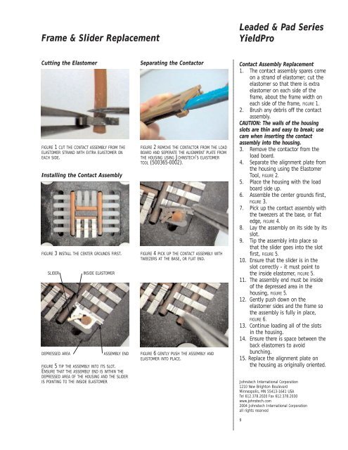
Frame & Slider Replacement<strong>Leaded</strong> & <strong>Pad</strong> <strong>Series</strong><strong>YieldPro</strong>Cutting the ElastomerFIGURE 1 CUT THE CONTACT ASSEMBLY FROM THEELASTOMER STRAND WITH EXTRA ELASTOMER ONEACH SIDE.Installing the Contact AssemblyFIGURE 3 INSTALL THE CENTER GROUNDS FIRST.SLIDERDEPRESSED AREAINSIDE ELASTOMERASSEMBLY ENDFIGURE 5 TIP THE ASSEMBLY INTO ITS SLOT.ENSURE THAT THE ASSEMBLY END IS WITHIN THEDEPRESSED AREA OF THE HOUSING AND THE SLIDERIS POINTING TO THE INSIDE ELASTOMERSeparating the ContactorFIGURE 2 REMOVE THE CONTACTOR FROM THE LOADBOARD AND SEPERATE THE ALIGNMENT PLATE FROMTHE HOUSING USING JOHNSTECH’S ELASTOMERTOOL (500365-0002).FIGURE 4 PICK UP THE CONTACT ASSEMBLY WITHTWEEZERS AT THE BASE, OR FLAT END.FIGURE 6 GENTLY PUSH THE ASSEMBLY ANDELASTOMER INTO PLACE.Contact Assembly Replacement1. The contact assembly spares comeon a strand of elastomer; cut theelastomer so that there is extraelastomer on each side of theframe, about the frame width oneach side of the frame, FIGURE 1.2. Brush any debris off the contactassembly.CAUTION: The walls of the housingslots are thin and easy to break; usecare when inserting the contactassembly into the housing.3. Remove the contactor from theload board.4. Separate the alignment plate fromthe housing using the ElastomerTool, FIGURE 2.5. Place the housing with the loadboard side up.6. Assemble the center grounds first,FIGURE 3.7. Pick up the contact assembly withthe tweezers at the base, or flatedge, FIGURE 4.8. Lay the assembly on its side by itsslot.9. Tip the assembly into place sothat the slider goes into the slotfirst, FIGURE 5.10. Ensure that the slider is in theslot correctly - it must point tothe inside elastomer, FIGURE 5.11. The assembly end must be insideof the depressed area in thehousing, FIGURE 5.12. Gently push down on theelastomer sides and the frame sothe assembly is fully in place,FIGURE 6.13. Continue loading all of the slotsin the housing.14. Ensure there is space between theback elastomers to avoidbunching.15. Replace the alignment plate onthe housing as originally oriented.<strong>Johnstech</strong> International Corporation1210 New Brighton BoulevardMinneapolis, MN 55413-1641 USATel 612.378.2020 Fax 612.378.2030www.johnstech.com2004 <strong>Johnstech</strong> International Corporationall rights reserved9