Building instructions Fournier RF-4D - Aero-naut
Building instructions Fournier RF-4D - Aero-naut
Building instructions Fournier RF-4D - Aero-naut

Create successful ePaper yourself
Turn your PDF publications into a flip-book with our unique Google optimized e-Paper software.
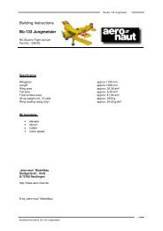
<strong>Fournier</strong> <strong>RF</strong>-<strong>4D</strong>PreparationThe wooden parts are drawn to reduced scale in these building <strong>instructions</strong>; write the part number on eachcomponent with a soft pencil, using the drawing as a guide. Remove the parts from the die-cut sheets usinga balsa knife where necessary. Check all parts for proper fit before installing them.If you are an experienced builder you may wish to alter the sequence described in these building<strong>instructions</strong>, but please think through the results of such changes.The building <strong>instructions</strong>, photographs, parts list, motor, retract unit and servos should be used constantly asaids to building. Note that the receiver and glowplug battery must be installed in the nose section.Before starting construction sand the surfaces of all the GRP parts thoroughly using 400-grit wet-and-dryabrasive paper. Make good any minor defects in the moulding using polyester filler paste, and finish off theedges of the cockpit area using the marked lines and photos as a guide.Important! the original machine was of wood construction, whereas our model features a moulded GRPfuselage. It is therefore important to keep the weight of the model’s tail end to an absolute minimum duringconstruction. Items such as the receiver battery and similar must be installed as far forward as possible inthe fuselage. You will almost certainly need to add nose ballast, especially if you fit a single-cylinder motor.Adhesives:Since the parts contained in the kit are very highly pre-fabricated, this section only calls for a few tipsregarding the use of epoxy laminating resin. Compared to quick-setting epoxy glues this resin offersimportant advantages: it can be applied more accurately to the actual glued joint; it also penetrates into thenarrowest of gaps, ensuring that joints are really strong. For some processes the resin should be thickenedwith a thixotropic agent; in this form it can be applied in exactly the right location, with no tendency to run off.Use coarse abrasive paper to roughen all areas of the fuselage which are to be glued. This is the only way toensure that glued joints are really strong and durable.Construction starts with trimming the motor bulkhead (77) to fit in the fuselage - just sand the bottom edge toa slight bevel to match the curvature of the fuselage. The position of the motor crankshaft axis is shown onthe plan. Be sure to mark the axes clearly on part (77).Cut a piece 195 mm long from the wing joiner sleeve (2) and fit it in the appropriate holes in the fuselage.Sand the outside of the sleeve if necessary, as it must not be a tight fit in the holes (risk of deforming thefuselage). Tack it in place with thin cyano, then reinforce the joints with laminating resin.Cut the opening for the wheel doors in the bottom of the fuselage. Take care - the front edge must be widerthan the rear to match the shape of the wheel doors (10), which are not symmetrical.Place the retract unit centrally on the retract unit support (3) and align it carefully. Drill 4 mm Ø holes asrequired. Fit the support (3) through the bottom opening in the fuselage in front of the joiner sleeve (2) asshown in Fig. 2, and raise it into position. The sides of part (3) must be trimmed so that it fits against thejoiner sleeve (2) as shown; use a pencil to mark where it has to be trimmed back, trim it, then offer it upagain until it fits as described.The retract support (3) now has to be soaked in laminating resin. Apply the resin repeatedly to the trimmedperiphery; the plywood will absorb the resin. Finally apply more resin to both sides of part (3) and allow it tocure fully. The retract unit can now be screwed to the support, and a fillet of thickened epoxy applied roundthe retaining nuts. Roughen the joint surfaces of the retract support and place it in the fuselage.With the retract unit and part (3) in the fuselage, set it to the “retracted” position. Cut a spacer about 2.5 mmthick (e.g. balsa) to size, place it on the bottom of the fuselage and slide it under the wheel; this ensures thatthere is a little clearance between the retracted wheel and the closed wheel doors (10). Position the retractunit support (3) in the fuselage and tack it in place with cyano. Remove the retract unit again and applyplenty of thickened epoxy to the joints. Fig. 4 shows a method which ensures good contact between theparts and the flat fuselage bottom.Gluing the wing joiner sleeves (2) in the wings: cut the remainder of part (2) in half and slide the sleevesinto the wing panels. The sleeves must not project beyond the root ribs; shorten them slightly if necessary.Seal one end of each sleeve with a piece of balsa about 8 - 10 mm thick. The sleeves must be sealed<strong>Fournier</strong> <strong>RF</strong>-<strong>4D</strong> building <strong>instructions</strong>3
<strong>Fournier</strong> <strong>RF</strong>-<strong>4D</strong>fueltank. With this installation the throttle servo has to be installed on the left-hand side of the fuselage. If youinstall a single-cylinder motor “side-winder” style, the servo will be mounted on the right-hand side.Back to the standard version; installation of a single-cylinder motor. Remove the machined inside sectionfrom the motor bulkhead; the two circular stiffening plates are parts (64). Fig. 5 shows the motor bulkheadwith an extension to accommodate the fueltank (see above) to suit the Saito FA-100T. The plywoodbulkhead (77) must be soaked thoroughly in laminating resin; see above re. part (3). When the epoxy hascured, fix the motor to the motor mount, position it as accurately as possible and drill the 5 mm Ø holes.Remove the motor mount and open up the holes to 6.5 mm Ø to accept the captive nuts supplied. Install themotor mount and motor and check that it is correctly positioned. Check also the distance to the front face ofthe propeller driver. The holes for the fuel system tubes and throttle linkage sleeve can now be drilled.To prevent oil and dirt entering the fuselage, the front face of the fuselage (= motor bulkhead) should beclosed off using one of the plywood plates (54). Lay the motor bulkhead on part (54) and mark the holes on itfrom the bulkhead (77). Fit the M5 mounting screws through the holes. Now mark the outline of the bulkhead(77) on part (54) and saw it to size. Soak part (54) with resin to prevent it absorbing fuel.Figs. 8 and 9 show the retract unit and air cylinder installed.Cut out the mudguard (35) using tin-snips, leaving a strip about 7 mm wide on both sides. Cut a slot in theside of the moulding to clear the actuating shaft of the retract unit. Cut the two parts (36) (15 - 20 mm long)from hardwood strip and glue them to the side strips at the bottom; 2.2 Ø x 6.5 mm self-tapping screws arefitted into these parts to attach the mudguard (35) to the fuselage floor. Fig. 38 shows approximately wherethe screws should be fitted in order to coincide with the blocks. Fig. 29 shows the mudguard and fueltank,which in this case is positioned to suit the Saito FA-100T.The co-ordinates for the screws should now be marked as accurately as possible on the fuselage bottomusing the mudguard as a template. Drill the holes 2.3 mm Ø. Place the mudguard in the fuselage (retract unitinstalled), drill the first 1.5 mm Ø hole and fit a screw to secure it. Carefully drill the remaining holes, takingcare not to deform the moulding. The mudguard must be located centrally in the fuselage.Figs. 10, 11 and 12 shows the plastic cockpit components. Please take a close look at Fig. 12, which showshow the instrument panel has to be trimmed (the side areas are located in the fuselage recess).Fig. 13 shows the hinge and actuating system of the wheel well doors (10). Important: the doors are notsymmetrical in the fore-and-aft direction. Align them carefully, and mark the front end. Bend the final 20 mmof the mild steel rods (11) at right-angles. Cut two pieces 78 mm long from the brass tube (12) and file anotch in the centre of each using a round file (lubricating point). Slip the tubes onto the steel rods (11). Thesecond bend at the front end of parts (11) should be located about 145 mm from the rear bend. Important:this bend must be located about 8 - 10 mm forward of the front face of the mudguard. Don’t forget: theseparts are “handed”, i.e. there are left-hand and right-hand hinge assemblies.Cut two pieces 15 mm long from part (13), fix them to the formed rods (11) with soft binding wire and solderthe parts together as shown in the photos and on the plan.Detail “X” on the plan shows a cross-section through the hinge system for the wheel doors (10) on thebottom of the fuselage. Note that the inside of parts (10) must be flush with the fuselage floor where thebrass bush (12) is located. The entire hinge / actuation system can now be glued to the wheel doors (10).Place a piece of 1.5 mm plywood between the tongues of parts (10) and lay the brass tube on the spacer;the shaft (part 11) should have about 0.5 mm clearance above the tongues, i.e. the wall thickness of parts(12). Position the parts as accurately as possible (the dimensions are stated in detail “X”), and glue them inplace using plenty of thickened laminating resin.Fig. 14 shows all the servo mounts. Please note that the elevators are actuated using two micro-servos, asthis arrangement allows the snake outers to be glued directly to the fuselage sides. Install a high-qualitymini-servo for the rudder. The throttle servo should be mounted on the right-hand side of the fuselage for asingle-cylinder motor. Figs. 15 - 18 also show how the servos are installed. Position the mounts in thefuselage, tack them in place with cyano, then reinforce the joints with laminating resin.The next step is to install the “snakes” in the fuselage; start by drilling the exit holes in the fuselage. Filethese out at a very flat angle to avoid kinking the snake inners (40). Fit an M2 nut and clevis (71) on eachthreaded coupler, slip them through the fuselage interior and out of the appropriate exit holes, then connect<strong>Fournier</strong> <strong>RF</strong>-<strong>4D</strong> building <strong>instructions</strong>5
<strong>Fournier</strong> <strong>RF</strong>-<strong>4D</strong>Cut pieces of aluminium tubing (44) about 5 mm long and press them into the GRP rudder hinge lugs (43).Trim the slots for the hinge lugs (43) in the tail post and insert them. Take a length of 3 mm Ø steel rod as atemporary rudder hinge shaft and slide it through the lugs: fit a 2 mm thick spacer (e.g. part 48) between thetrailing edge of the fin and the shaft at the top, and a 3 mm plywood spacer at the bottom. Align the shaft asaccurately as possible (it must be central) and tack parts (43) to the tail post with cyano. Glue the sleeves inthe lugs at the same time - see Fig. 43. Apply a drop of laminating resin to each joint for reinforcement.Cut four parts from the aluminium tube (44) as shown in Figs. 44 and 45; the bottom piece should projectslightly below the line of the fuselage. Press the rudder (46) against the fin to mark the position of the hingelugs (43), and cut the slots for them using a balsa knife - Fig. 46. It should be possible for the whole length ofthe rudder leading edge to rest against the tube (44). Fig. 47 shows how the rudder is aligned with the fin.Position the rudder as accurately as you can, then tack the four pieces of tubing (44) to it using cyano.Reinforce the joints in the usual way, but not before removing the shaft and rudder - see Fig. 48.Divide the rudder leading edge (47) as shown in Fig. 49, and cut small recesses to clear the pieces of tube(44) glued in the hinge lugs (43). Determine the length of the leading edge sections (47) from the rudderitself, and glue the pieces to the front face of the rudder.The rudder leading edge should be 8 mm thick at the top, but full thickness (12 mm) at the bottom. Round offthe leading edge step by step as shown in sections D-D and E-E on the plan. The gap between fin andrudder should be narrow and even, but must permit rudder travels of at least +/- 30° - see Figs. 50 and 51.Cut a slot for the tailskid actuator (48) using a fine-bladed fretsaw - see fuselage side elevation and sectionE-E. File a notch in the front edge of part (48) if necessary to avoid obstructing the rudder hinge shaft (44).Cut a slot for the rudder horn, but don’t glue it in place until the rudder has been covered; the same appliesto all the control surface horns. Important: all horns (5 off) must be roughened with coarse abrasive paperbefore gluing them in their slots. Drill out the linkage holes to 1.6 mm Ø beforehand to accept the clevis pins.For the tailskid bush (machined aluminium part) drill an 8 mm Ø hole about 48 - 50 mm forward of the tailend of the fuselage. The coil springs (56) must be installed under light tension. Roughen the bush and degreaseit before fixing it in place with plenty of epoxy.The fuselage is now almost complete, and we can turn to the fuel supply. If the usual rules are followed(carburettor level with centreline of fueltank) the usable space for the tank is somewhat restricted. If you wishto install the tank above the mudguard, it should be of a very low-profile type; a very good choice is theSimprop “square” type of 340 cc capacity. It has to be located slightly higher than the ideal position, but witha single-cylinder four-stroke mounted side-winder the carburettor is fairly high in any case - an acceptablesolution.If you wish to carry more fuel than that, two smaller tanks can be connected in series, as shown on the plan.In this case you can also set the “ideal” installation height for the actual motor you are using. Important: thefiller / drain line for the system must be sealed for flying (e.g. by fitting an M3 x 10 mm screw in the end).Oval fueltanks of 240 cc capacity are ideal for the twin-tank arrangement.The two tailplane panels are glued to the fuselage using a pair of CFRP joiner tubes (60). First cut the tube(60) in two as shown on the plan, and check that the tubes are an easy sliding fit in the fuselage. Trim theholes if necessary.We recommend the following method of gluing the joiner tubes (60) in the fin:- Apply adhesive tape over the moulded-in tailplane root fairings and apply a coat of mould-release wax tothe tape. Open up the holes using a sharp balsa knife.- Glue pieces of balsa in both ends of the tubes (60) to seal them.- The front joiner tube (60) should now be glued in (say) the left-hand tailplane panel, the rear tube in theright-hand panel using thickened laminating resin. This is the procedure:- Apply plenty of epoxy to the inside of the holes and distribute it carefully using a length of dowel or steelrod. Slowly push the tube into the hole, twisting it to and fro as you do so. Watch the depth! If no epoxy issqueezed out of the root rib, apply more epoxy. Remove excess resin then clean any excess epoxy fromthe tube using acetone.- Now leave the epoxy to semi-harden; the time this takes depends on the room temperature. The tubesshould now be slightly difficult to move. At this point fit both tailplane panels into the fuselage, align them<strong>Fournier</strong> <strong>RF</strong>-<strong>4D</strong> building <strong>instructions</strong>7
<strong>Fournier</strong> <strong>RF</strong>-<strong>4D</strong>carefully and leave the epoxy to cure fully. When the epoxy is hard, withdraw the parts from the fuselageand - if necessary - trim the tailplane panels to match the root fairings on the fuselage.- The tailplane panels should not be installed permanently until the fuselage has been painted and thetailplane covered.You have already rubbed down the fuselage, but it must now be thoroughly de-greased before painting. Anexcellent method is to wash it using water with liquid detergent added. Wipe the entire surface with a wetcloth to remove grease, then rinse it more using clean water. Seal all the fuselage openings beforehand.Our <strong>RF</strong>-<strong>4D</strong> was sprayed with a base coat of Orapaint and sealed with Orapaint EKS clear lacquer (glossfinish). A highly convincing finish is obtained if you thin the clear lacquer very greatly (approx. 300%thinners).Installing the tailplane is now extremely simple: first roughen the joint surface of the integral root fairingsusing coarse abrasive paper. Apply sufficient thickened epoxy to the holes in the tailplane panels anddistribute it evenly. Apply the same epoxy mixture to the root face of the tailplane panels. Apply a thincoating of epoxy to the joiner tubes (60) (already bonded-in) and slide them through the fuselage. Removeexcess resin with a paper towel and clean the surfaces with petrol. Apply a few drops of epoxy to the insidejoints between fuselage and joiner tubes, working through the openings in the tail post.When the resin has started to cure, press the parts together finally, clean the area once more and tape thetailplane panels to the fuselage.Now it’s the rudder’s turn: apply Vaseline to all parts of the hinge system, and only then fit the hinge shaft(45). Secure the shaft at the bottom.Thread the coil springs (56) into the tailskid actuator (48) and connect the other end to the lever on thetailskid. Apply a drop of thread-lock fluid to the threaded part of the tailskid retaining screw. Now place thecoil springs under light tension, fit the screw in the actuator and tighten it. Apply a drop of oil for lubrication.After covering the elevator panels, glue the elevator horns (49) in the slots and attach the panels to thetailplane using the hinges (61). Grease the snake inners lightly and slide them into the outer sleeves from thefront end. Connect the inners to the servo output arms. Connect clevises and threaded couplers to theelevator horns and establish the correct length of the snake inners (servos and elevators neutral / central).Cut off excess pushrod length and crimp the threaded couplers firmly onto the pushrods.The fuselage and cockpit can now be fitted out permanently. Important: before fitting the mudguard checkthe operation of the retract system carefully. It is important that the wheel doors work reliably every time.To install the retract unit we recommend a right-angled 3 mm A/F ball-end allen driver at least 125 mm long.This tool makes it relatively easy to reach the retract unit retaining screws through the opening in the motorbulkhead. Tighten the screws really firmly, and check again that they are really tight. Install the air cylinderand ensure that the control pin of the retract unit reaches the end-point of its guide. If not, adjust the clevisuntil it does. Tighten the actuating arm really thoroughly on its shaft.The air lines can now be connected: fit the hoses full-depth onto the nipples; this is easier if you first softenthe hose slightly with heat from a match. Tighten the grubscrew in the pressure reducer until it is about 0.5 -1 mm below the surface of the body. The retraction time should be set to about two seconds. Pressurise thesystem - it is not necessary to set a pressure higher than 6 bar.Completing the wings starts with gluing the incidence tubes (67) in the root ribs: saw two pieces about 25mm long from the brass tube (67), and seal one end of each. Check that the tubes are an easy sliding fit inthe holes in the fuselage root fairings. Fit the wing joiner tube through the fuselage and provisionally plug inthe wings. Check that the trailing edge of the wings and the root fairings line up correctly. If necessary adjustthe hole in the root rib. Apply thickened epoxy to the hole in the root rib, press the tubular incidence peg intoit and wipe off excess resin. Allow the epoxy to harden slightly, then clean any resin residues from the tubeusing acetone and apply mould-release wax to it. Now push the wing against the fuselage as far as it will goand check that the end of the incidence tube does actually protrude inside the fuselage. Align the trailingedge of the wing and root fairing, then tape the parts together.Fig. 52 shows how the threaded sleeve for the wing retainer system (75) is installed. Use an M5 screw and,<strong>Fournier</strong> <strong>RF</strong>-<strong>4D</strong> building <strong>instructions</strong>8
<strong>Fournier</strong> <strong>RF</strong>-<strong>4D</strong>say, a captive nut to screw the sleeve in place. Fit the joiner tube in the wing and set the M5 screw parallel toit. Tap the sleeve into the root rib. The threaded rod of the retainer (75) must lie parallel to the wing joinertube.Stick a sheet of new abrasive paper (approx. 180-grit) to a flat sanding block, and use this to sand the wingsurfaces to a fine finish. Three templates are supplied (S1 - S3) for shaping the wing leading edge to theexact profile; sand the root to match the fuselage root fairing. The trailing edge should also be carefullysanded down to an even thickness of about 0.5 - 1 mm. Trim the wingtips (63) roughly to follow the wingsection, glue them in place, then finish them off using a balsa plane and the sanding block.Remove foam from the servo wells to provide proper clearance, keeping the servo cable openings free. Forthe aileron linkage we recommend mini-sized wing-mounting servos, whereas good micro-servos aresufficient for the airbrakes. Figs. 55 and 56 show how the servos are mounted on the plywood plates (68).Glue the plates in the wings using thickened epoxy.Dismantle the airbrakes (69) as shown in Fig. 53 (just push the levers out of the bottom pivots using ascrewdriver) and place the box in the slot in each wing. The top edge of the box should be recessed about1.5 mm under the top surface; adjust the brake slot if necessary until this is the case. Roughen thealuminium box with coarse abrasive paper, de-grease the surfaces and glue it in the slot using thickenedepoxy. Cut in-fill pieces (73) from the balsa strip to cover the top flanges of the box. When the glue has sethard, trim the edges of the strips to provide clearance for the brake, and install the airbrake. Cut the airbrakecapstrip from part (73) leaving about 1 mm clearance all round the edges. Tack the capstrip to the airbrakeblade using cyano, then carefully sand all three strips flush with the wing surface. Extend the airbrake,remove it and reinforce the joints with epoxy.Important: each airbrake servo should be connected to its own receiver channel, i.e. please don’t use Y-leads. This way it is much easier to synchronise the brakes. The servos are already in place (but notpermanently); run them to the “brakes retracted” end-point.The servo linkage consists of the threaded rod (70) and clevis (72). The rods (70) must first be cut to correctlength. Connect the clevis (72) to the airbrake, slip it into the box and press it onto the pivots. The pushrod(70) projects into the servo well. The pushrod (70) must be pulled forward (towards the wing root) to its endpointto give access to the brake mechanism. Using a soft pencil mark the position of the hole in the servooutput arm on the pushrod (70), then remove the brake again. Bend the pushrod (70) at right-angles asaccurately as you can at the marked point, cut off the excess rod length and file the end smooth. Re-installthe brake. The position of the bend will probably not be exactly right, so screw the pushrod (70) in or out ofthe clevis (72) to correct the length. Check the operation of the airbrake system from the transmitter. Removethe airbrake again and cut two washers about 5 mm Ø from the scrap vacuum-moulding material, with a 1.6mm Ø hole. Slip these onto the bent pushrod (7) and fix them to the rod with Loctite when the airbrakes arefinally installed (wing top surface covered).Remove the stiffening plates (64) from the motor bulkhead, drill 2.5 mm Ø holes in them as shown and pushthe outboard wheel supports (76) into them. Cut channels for the 4 mm Ø hardwood dowels as shown on theplan and Fig. 62, and fit the outboard wheels together with the aluminium spreader plates in the plates (64).Apply a drop of oil to the end of the three M2.5 mm pan-head screws. Fit these assemblies in the wing, anddrill 4 mm Ø holes as shown on the plan and section F-F to accept the hardwood dowels (65). Remove allthe parts and clear away the scrap foam from the recess. The parts are glued in place using thickenedepoxy: apply plenty of resin in the recess, then press the complete assembly into place. Mix up some freshlow-viscosity resin and gradually fill the side holes until you are confident of a really strong glued joint. Thedowels (65) ensure that the landing loads are spread adequately in the wing.We recommend using twisted 0.25 mm² cable for the servo extension leads. Solder the aileron servo directlyto the extension lead, and attach the airbrake servo cable to the aileron lead using a heat-shrink sleeve orsimilar (the airbrake servo cannot be soldered to the extension lead until the loom has been fitted throughthe wing). The cable can easily be drawn through the wing using a length of 0.8 mm Ø steel rod: form a loopin one end, fit this through the root rib and tie the extension cable to the loop using soft binding wire orsimilar; the lead can now be pulled through the wing. Solder the brake servo to the extension lead - see Fig.57 - and a 6-pin plug. Glue the matching socket in the fuselage.Sand the top edge of the aileron leading edge to a chamfer as shown in section G-G and cut slight recessesto accommodate the central knuckle of the hinges - see Fig. 59. Cut slots for the aileron horns; these must<strong>Fournier</strong> <strong>RF</strong>-<strong>4D</strong> building <strong>instructions</strong>9
<strong>Fournier</strong> <strong>RF</strong>-<strong>4D</strong>be sanded at a slight angle as shown in Fig. 54. Tack the horns in place using cyano, then reinforce thejoints with epoxy.Cut in half the threaded rod for the wing retainer system (75) and screw the locknut and locking mechanismonto it. The outer locknuts should be about 196 mm apart (outside of nuts). Ensure that the lockingmechanism is in the centre, so that you can reach it through the opening in the hatch cover (54). Open thelocking mechanism, screw the threaded rods into the wing roots and fit the wings on the fuselage. Carry outany fine adjustments to the length, then tighten the locknuts.Fit the cowl over the motor on the fuselage and fit the spinner or the spinner backplate. The cowl can now betrimmed: first trim the bottom section to fit, and secure it with four 2.2 Ø x 6.5 mm self-tapping screws. Addthe top section and mark the position of the dummy exhausts. Cut three pieces of limewood strip (36) eachabout 12 mm long, and glue them to the inside top edge of the bottom cowl section (the overlap) as shown inFig. 42. Drill 1.5 mm Ø holes to accept the remaining 2.2 Ø x 6.5 mm self-tapping screws. Place the top cowlsection on the model, align it carefully and tape it in place. Drill 1.5 mm Ø holes for the retaining screws.Open up these holes in the top cowl section only to 2.3 mm Ø.This completes the construction of your model, and all that remains is to set the correct control surfacetravels:AileronsElevatorRudder+ approx. 12 - 16mm- approx . 7 mm± approx. 15 mmas much as possibleTest-flying:The most important point to note here is the wind direction: please take great care to line up, take off andland directly into wind, as any sideways drift places an unnecessary strain on the main undercarriage.Once airborne the model is completely straightforward to fly. The characteristics of the wing ensureabsolutely docile handling. Moderate “classic” aerobatics are possible; carefully flown loops, impressive stallturns, reversals, rolls and similar manoeuvres present no problems. At landing time use the airbrakes tocontrol the final approach (glide angle).If your motor should quit in flight and you have to carry out an out-landing, we recommend that you completethe emergency landing with the wheel retracted - just as the full-size pilots do - unless the landing surface isvery smooth.We hope you have loads of pleasure flying your model. Happy landings!<strong>Fournier</strong> <strong>RF</strong>-<strong>4D</strong> Parts ListNo. Description No. off Material Dimensions in mm1 Fuselage 1 GRP Ready made2 Wing joiner sleeve GRP Ready made3 Retract unit support 1 Plywood Ready made4 Retract unit 1 Dural + steel + rubber Ready made5 Air cylinder 1 Dural + steel Ready made6 Air cylinder plate 1 Plywood 3mm, die-cut7 Hardwood strip Spruce 5 x 3 mm8 Instrument panel 1 ABS Ready made9 Baggage compartment 1 ABS Ready made10 Wheel door 2 Plywood Ready made11 Wheel door lever 2 Plated mild steel 2 mm Ø12 Wheel door bush 2 Brass tube 2 Ø / 3 mm Ø x 78 mm13 Guide 2 Brass tube 0.9 Ø / 1.3 mm Ø x 15 mm14 Air exit 1 Plywood 3 mm, die-cut15 Wheel door guide 2 Steel rod Ready made16 Compressed air tank support 2 Plywood 3 mm, die-cut17 Servo plate, R.H. 1 Plywood 3 mm, die-cut18 Micro-servo support 2 Plywood 3 mm, die-cut19 Side part 3 Plywood 3 mm, die-cut<strong>Fournier</strong> <strong>RF</strong>-<strong>4D</strong> building <strong>instructions</strong>10
<strong>Fournier</strong> <strong>RF</strong>-<strong>4D</strong>20 Servo plate, L.H. 1 Plywood 3 mm, die-cut21 Side part 1 Plywood 3 mm, die-cut22 Mini-servo support 1 Plywood 3 mm, die-cut23 Side part 1 Plywood 3 mm, die-cut24 Throttle servo support 1 Plywood 3 mm, die-cut25 Side part 2 Plywood 3 mm, die-cut26 Cockpit floor 1 Plywood 3 mm, die-cut27 Retract servo support 1 Plywood 3 mm, die-cut28 Side part 3 Plywood 3 mm, die-cut29 Control valve support 1 Plywood 3 mm, die-cut30 Pilot’s seat 1 ABS Ready made31 Seat backrest 1 ABS Ready made32 Seat in-fill piece 1 Plywood 3 mm, die-cut33 Seat in-fill piece 1 Plywood 3 mm, die-cut34 Seat in-fill piece 1 Plywood 3 mm, die-cut35 Mudguard 1 ABS Ready made36 Hardwood support strip 1 Limewood 6 x 6 mm37 Joystick fairing 1 ABS Ready made38 Triangular strip 1 Balsa 15 x 15 mm39 “Snake” outer sleeve 3 Plastic 2 Ø / 3.2 mm Ø, white40 “Snake” inner sleeve 3 Plastic + steel 2 mm Ø41 “Snake” outer sleeve 1 Plastic 2 Ø / 3.2 mm Ø, red42 Hardwood strip 1 Limewood 5 x 10 mm43 Rudder hinge lug 3 GRP Ready made44 Aluminium tube 1 Aluminium 3 Ø / 4 mm Ø45 Aluminium tube 1 Aluminium 2 Ø / 3 mm Ø46 Rudder 1 Styrofoam + balsa Ready made47 Rudder leading edge 1 Balsa 12 x 12 x 370 mm, slotted48 Tailskid actuator 1 GRP Ready made49 Control surface horn 5 GRP Ready made50 Motor mount 1 Dural + steel Complete set51 Bottom cowl section 1 GRP Ready made52 Top cowl section 1 GRP Ready made53 Canopy 1 Plastic Ready made54 Hatch cover 2 Plywood 1 mm55 Tailskid, complete 1 Steel + aluminium Complete set56 Coil spring 2 Steel Ready made57 Spinner 1 Dural + plastic Ready made58 Tailplane panel 2 Styrofoam + balsa Ready made59 Tailplane tip 2 Balsa Oversize60 CFRP tube 1 CFRP 6 Ø / 8 mm Ø61 Control surface hinge 14 Plastic Ready made62 Wing panel, L.H. / R.H. 1 + 1 Styrofoam + obechi Ready made63 Wingtip 2 Balsa Oversize64 Stiffening plate 2 Plywood 25 Ø x 8 mm65 Hardwood dowel 1 Beech 4 mm Ø66 Wing joiner tube 1 Dural 16 Ø / 18 Ø x 498 mm67 Tubular incidence peg 1 Brass 4 Ø / 5 mm Ø68 Servo plate 4 Plywood 1 mm, die-cut69 Airbrake 2 Aluminium + brass Ready made70 Threaded rod 4 Plated mild steel M2 / 1.6 mm Ø71 Clevis 10 Chrome-plated steel Ready made72 Clevis 2 Nylon Ready made73 Plate 1 Balsa 2 mm, oversize74 Servo well cover, L.H. / R.H. 1 + 1 Plastic Ready made75 Wing retainer system, complete,including <strong>instructions</strong> 1 Plastic + steel Ready made76 Outboard wheel, complete 2 Dural + steel Ready made77 Motor bulkhead 1 8 mm plywood Ready madeS1-S3 Profile template 1 each Plywood 3 mm, die-cut<strong>Fournier</strong> <strong>RF</strong>-<strong>4D</strong> building <strong>instructions</strong>11
<strong>Fournier</strong> <strong>RF</strong>-<strong>4D</strong><strong>Fournier</strong> <strong>RF</strong>-<strong>4D</strong> building <strong>instructions</strong>12
<strong>Fournier</strong> <strong>RF</strong>-<strong>4D</strong><strong>Fournier</strong> <strong>RF</strong>-<strong>4D</strong> building <strong>instructions</strong>13
<strong>Fournier</strong> <strong>RF</strong>-<strong>4D</strong>Plan text1 Adjust shape of spring2 There is plenty of space in front of the mudguard for two fueltanks connected in series; approximateposition of tanks shown.3 Carburettor4 Diagram of fueltanks connected in series; see building <strong>instructions</strong>5 System fill / drain line6 System vent / overflow lineA Fuel supply tankB Secondary fueltank7 Retract unit air system installation shown in “wheel down” position; see building <strong>instructions</strong>.8 Pressure reducer9 Cam disc10 Air cylinder11 Air exit12 Control valve13 One-way filler valve14 Compressed air tank15 Adaptor16 Air pump17 Trailing edge of GRP fin18 Pivot axis of rudder - see sections D-D and E-E19 Left-hand fuselage side20 Right-hand fuselage side21 See Figs. 21 - 2422 Centre of Gravity (C.G.), 100 - 115 mm23 Propeller driver24 Lever (11) shown in “door (= wheel) retracted”25 Opening for wheel doors (10); extend forward to overall length of 152 mm26 Full-height view of part (35)27 Installation of plate (6); see building <strong>instructions</strong>28 Support for cockpit floor (26)29 Section C-C30 Velcro tape31 See building <strong>instructions</strong>32 Section B-B33 Section D-D34 Section E-E35 Chamfer top edge of aileron as shown36 Soldered joint37 Section G-G38 Section F-F39 Cut grooves in part (64) before gluing in place - see building <strong>instructions</strong>.40 Disc: see outboard wheel41 WE RESERVE THE RIGHT TO MODIFY ANY FEATURE IN ORDER TO IMPROVE OURPRODUCTS42 Wheel extended43 Wheel retracted44 Detail “X”, scale 2:145 Wing retainer system: see <strong>instructions</strong> supplied with set46 Seal end of part (2) with balsa!47 Servo connection: see building <strong>instructions</strong>48 Parts (70) and (72); see Fig. 61<strong>Fournier</strong> <strong>RF</strong>-<strong>4D</strong> building <strong>instructions</strong>14