QUIRLI - Green Hobby & Model
QUIRLI - Green Hobby & Model
QUIRLI - Green Hobby & Model

Sie wollen auch ein ePaper? Erhöhen Sie die Reichweite Ihrer Titel.
YUMPU macht aus Druck-PDFs automatisch weboptimierte ePaper, die Google liebt.
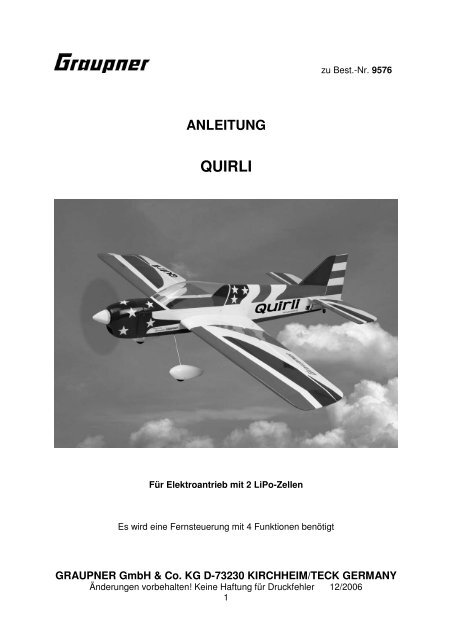
zu Best.-Nr. 9576<br />
ANLEITUNG<br />
<strong>QUIRLI</strong><br />
Für Elektroantrieb mit 2 LiPo-Zellen<br />
Es wird eine Fernsteuerung mit 4 Funktionen benötigt<br />
GRAUPNER GmbH & Co. KG D-73230 KIRCHHEIM/TECK GERMANY<br />
Änderungen vorbehalten! Keine Haftung für Druckfehler 12/2006<br />
1
Technische Daten<br />
Spannweite ca.<br />
1010 mm<br />
Rumpflänge ohne Spinner ca. 905 mm<br />
Tragflächeninhalt ca.<br />
22 dm²<br />
Höhenleitwerksinhalt ca.<br />
5,5 dm²<br />
Gesamtflächeninhalt ca.<br />
27,5 dm²<br />
Fluggewicht je nach<br />
Ausrüstung ca.<br />
830 g<br />
EWD ca. 0,5°<br />
Schwerpunktbereich gemessen ca. mm<br />
Vorderkante Nasenleiste<br />
Vorwort<br />
Das GRAUPNER <strong>Model</strong>l <strong>QUIRLI</strong> ist ein superleichter, formschöner<br />
Kunstflugtrainer. Es wurde besonders Wert auf ein geringes Abfluggewicht gelegt,<br />
was sich in den Flugleistungen und Flugeigenschaften wiederspiegelt. Die<br />
Flugeigenschaften machen den <strong>QUIRLI</strong> zum idealen <strong>Model</strong>l für den Einstieg in<br />
dreiachsgesteuerte <strong>Model</strong>le. Einfacher Kunstflug ist möglich. Durch den großen<br />
Tragflächeninhalt und das verwendete Profil besitzt das <strong>Model</strong>l sehr gutmütige und<br />
neutrale Flugeigenschaften. Der Aufbau des <strong>Model</strong>ls ist überwiegend aus Balsaholz<br />
gefertigt. An besonders beanspruchten Stellen sind Verstärkungen aus Sperrholz<br />
eingeleimt.<br />
Die Tragflügel sind teilbar, so dass sie auch in einer Packtasche am Fahrrad<br />
transportiert werden können. Rumpf, Tragflügel, Seiten- und Höhenleitwerk sind mit<br />
mehrfarbiger Bügelfolie bespannt. Für die Fertigstellung sind nur wenige<br />
Arbeitsgänge notwendig, wie z.B. das Einkleben des Seitenleit- und Höhenleitwerks,<br />
den Einbau von Motorträger mit Motor, des Fahrwerks sowie die Fernlenkanlage mit<br />
ihren Anlenkungen.<br />
Zum Fliegen des <strong>Model</strong>ls reicht eine RC-Anlage mit 4 Funktionen.<br />
Achtung: Dieses <strong>Model</strong>l ist kein Spielzeug!<br />
Sollten Sie mit solch motorisiertem <strong>Model</strong>l keine Erfahrung haben, wenden Sie sich<br />
bitte an erfahrene <strong>Model</strong>lflieger, die Sie unterstützen können. Es könnte zu<br />
Verletzungen kommen, wenn das <strong>Model</strong>l ohne Vorkenntnisse in Betrieb genommen<br />
wird. Denken Sie an die Sicherheit und Ihre Gesundheit.<br />
Wichtige Sicherheitshinweise<br />
Sie haben einen Bausatz erworben, aus dem – zusammen mit entsprechendem<br />
geeignetem Zubehör – ein funktionsfähiges RC-<strong>Model</strong>l fertiggestellt werden kann.<br />
Die Einhaltung der Montage- und Betriebsanleitung im Zusammenhang mit dem<br />
<strong>Model</strong>l sowie die Installation, der Betrieb, die Verwendung und Wartung der mit dem<br />
<strong>Model</strong>l zusammenhängenden Komponenten können von GRAUPNER nicht<br />
überwacht werden. Daher übernimmt GRAUPNER keinerlei Haftung für Verluste,<br />
Schäden oder Kosten, die sich aus dem fehlerhaften Betrieb, aus fehlerhaftem<br />
Verhalten bzw. in irgendeiner Weise mit dem vorgenannten zusammenhängend<br />
ergeben. Soweit vom Gesetzgeber nicht zwingend vorgeschrieben, ist die<br />
Verpflichtung der Firma GRAUPNER zur Leistung von Schadensersatz, aus welchem<br />
Grund auch immer ausgeschlossen (inkl. Personenschäden, Tod, Beschädigung von<br />
Gebäuden sowie auch Schäden durch Umsatz- oder Geschäftsverlust, durch<br />
GRAUPNER GmbH & Co. KG D-73230 KIRCHHEIM/TECK GERMANY<br />
Änderungen vorbehalten! Keine Haftung für Druckfehler 12/2006<br />
2
Geschäftsunterbrechung oder andere indirekte oder direkte Folgeschäden), die von<br />
dem Einsatz des <strong>Model</strong>ls herrühren.<br />
Die Gesamthaftung ist unter allen Umständen und in jedem Fall beschränkt auf den<br />
Betrag, den Sie tatsächlich für dieses <strong>Model</strong>l gezahlt haben.<br />
Die Inbetriebnahme und der Betrieb des <strong>Model</strong>ls erfolgt einzig und allein auf<br />
Gefahr des Betreibers. Nur ein vorsichtiger und überlegter Umgang beim<br />
Betrieb schützt vor Personen- und Sachschäden.<br />
Nach der neuen Regelung des §103 Abs. 3 LuftVZO müssen alle Flugmodelle, egal<br />
ob Slowflyer, Parkflyer, Segelflugzeuge, Flugmodelle mit Antrieben jeglicher Art vor<br />
Aufnahme des Flugbetriebs versichert sein. Schließen Sie daher eine spezielle RC-<br />
<strong>Model</strong>l-Haftplichtversicherung ab. Fragen hierzu, werden Ihnen vom Fachhandel<br />
gerne beantwortet.<br />
Diese Sicherheitshinweise müssen unbedingt aufbewahrt werden und müssen bei<br />
einem Weiterverkauf des <strong>Model</strong>ls an den Käufer weitergegeben werden.<br />
Garantiebedingungen<br />
Die Garantie besteht aus der kostenlosen Reparatur bzw. dem Umtausch von<br />
solchen Teilen, die während der Garantiezeit von 24 Monaten, ab dem Datum des<br />
Kaufes nachgewiesene Fabrikations- oder Materialfehler aufweisen. Weitergehende<br />
Ansprüche sind ausgeschlossen. Transport-, Verpackungs- und Fahrtkosten gehen<br />
zu Lasten des Käufers. Für Transportschäden wird keine Haftung übernommen. Bei<br />
der Einsendung an GRAUPNER bzw. an die für das jeweilige Land zuständige<br />
Servicestelle sind eine sachdienliche Fehlerbeschreibung und die Rechnung mit dem<br />
Kaufdatum beizufügen. Die Garantie ist hinfällig, wenn der Ausfall des Teils oder des<br />
<strong>Model</strong>ls von einem Unfall, unsachgemäßer Behandlung oder falscher Verwendung<br />
herrührt.<br />
Wichtig! Bevor Sie mit dem Bau beginnen!<br />
Auch wenn Sie schon viele RC-<strong>Model</strong>le gebaut haben, lesen Sie diese Anleitung<br />
genauestens durch und kontrollieren Sie die Teile dieses Bausatzes auf<br />
Vollständigkeit. Es wurde viel Mühe darauf verwandt, den Aufwand möglichst<br />
einfach zu halten, ohne die Sicherheit zu beeinträchtigen.<br />
Das weitgehend vorgefertigte <strong>Model</strong>l benötigt nur noch wenig Bauzeit. Aber die<br />
verbleibenden Arbeiten sind wichtig und müssen sorgfältig ausgeführt werden. Von<br />
deren einwandfreier Ausführung hängt es ab, ob das <strong>Model</strong>l letztlich die<br />
vorgesehene Festigkeit und Flugeigenschaften haben wird; deshalb langsam und<br />
präzise arbeiten!<br />
Hinweise zur Folienbespannung<br />
Auf Grund von starken Wetterveränderungen (Temperatur, Feuchtigkeit etc.) können<br />
in der Bespannfolie kleine Falten auftreten. In seltenen Fällen auch ein Verzug der<br />
Bauteile. Dies liegt in der Natur der Holzbauweise mit Folienbespannung. Es kann,<br />
wie folgt, mit einem Heißluftgebläse (Fön) oder Folienbügeleisen, wie sie für den<br />
<strong>Model</strong>lbauer angeboten werden, wieder korrigiert werden.<br />
GRAUPNER GmbH & Co. KG D-73230 KIRCHHEIM/TECK GERMANY<br />
Änderungen vorbehalten! Keine Haftung für Druckfehler 12/2006<br />
3
Falten:<br />
Glattbügeln oder mit Warmluft anblasen und mit weichem Tuch<br />
anreiben.<br />
Verzogener Flügel: Flügel dem Verzug entgegen leicht verdreht aufspannen und mit<br />
Bügeleisen oder Warmluft die Bespannung wieder glätten.<br />
Vorsicht! Nicht mehr Wärme zuführen, als unbedingt notwendig. Bei zu heißem<br />
Bügeleisen schmilzt die Folie und es entstehen Löcher.<br />
Wenn Blechschrauben in Holz eingeschraubt werden, diese durch Weißleim<br />
gegen Lösen sichern: Weißleim in Bohrung einspritzen und Schraube<br />
eindrehen.<br />
Hinweis zur Benutzung von <strong>QUIRLI</strong><br />
Vor dem Versuch der ersten Inbetriebnahme muss die gesamte Betriebs- und<br />
Montageanleitung sorgfältig gelesen werden. Sie alleine sind verantwortlich<br />
für den sicheren Betrieb Ihres RC-Flugmodells. Bei Jugendlichen unter 14<br />
Jahren muss der Bau und Betrieb von einem Erwachsenen, der mit den<br />
Gegebenheiten und möglichen Gefahren eines RC-Flugmodells vertraut ist,<br />
verantwortlich überwacht werden.<br />
Diese Bedienungsanleitung muss sorgfältig aufbewahrt und im Falle einer<br />
Weitergabe dem nachfolgenden Benutzer unbedingt mit ausgehändigt werden.<br />
Fragen, die die Sicherheit beim Betrieb des RC-Flugmodells betreffen, werden<br />
Ihnen vom Fachhandel gerne beantwortet.<br />
Fernsteuer-Flugmodelle sind sehr anspruchsvolle und gefährliche<br />
Gegenstände und erfordern vom Betreiber einen hohen Sachverstand, Können<br />
und Verantwortungsbewusstsein.<br />
Rechtlich gesehen, ist ein Flugmodell ein Luftfahrzeug und unterliegt<br />
entsprechenden Gesetzen, die unbedingt eingehalten werden müssen. Die<br />
Broschüre »<strong>Model</strong>lflugrecht, Paragrafen und mehr«, Best.-Nr. 8034.01, stellt<br />
eine Zusammenfassung dieser Gesetze dar; sie kann auch beim Fachhandel<br />
eingesehen werden. Ferner müssen postalische Auflagen, die die<br />
Fernlenkanlage betreffen, beachtet werden. Entsprechende Hinweise finden<br />
Sie in der Bedienungsanleitung Ihrer Fernsteueranlage.<br />
Es dürfen nur die im Bausatz enthaltenen Teile, sowie die ausdrücklich von<br />
uns empfohlenen Original-Graupner-Zubehör- und Ersatzteile verwendet<br />
werden. Wird auch nur eine Komponente der Antriebseinheit geändert, ist ein<br />
sicherer Betrieb nicht mehr gewährleistet und es erlischt jeglicher etwaiger<br />
Garantieanspruch.<br />
Verwenden Sie immer nur passende, verpolungssichere Steckverbindungen.<br />
Alle stromführenden Leitungen, Steckverbindungen, sowie die<br />
Antriebsbatterie, bei Selbstkonfektionierung, kurzschlusssicher isolieren.<br />
Kombinieren Sie niemals unterschiedliche, z. B. Blech- und Goldkontakte, da<br />
hier keine sichere Funktion gewährleistet ist.<br />
Bei Verwendung von Schaltern bzw. Reglern mit Empfängerstromversorgung<br />
nur Steckverbindungen mit Graupner-Gold-Kontakten verwenden.<br />
GRAUPNER GmbH & Co. KG D-73230 KIRCHHEIM/TECK GERMANY<br />
Änderungen vorbehalten! Keine Haftung für Druckfehler 12/2006<br />
4
Kurzschlüsse und Falschpolungen vermeiden.<br />
Durch die hohe Energie der LiPo-Batterien besteht Explosions- und<br />
Brandgefahr.<br />
Ein RC- Flugmodell kann nur funktionsfähig sein und den Erwartungen<br />
entsprechen, wenn es im Sinne der Bauanleitung sorgfältigst gebaut wurde.<br />
Nur ein vorsichtiger und überlegter Umgang beim Betrieb schützt vor<br />
Personen- und Sachschäden. Niemand würde sich in ein Flugzeug setzen und<br />
- ohne vorausgegangene Schulung - versuchen, damit zu fliegen. Auch<br />
<strong>Model</strong>lfliegen will gelernt sein.<br />
Der Hersteller hat jedoch keine Möglichkeit, den Bau und den Betrieb eines<br />
RC- Flugmodells zu beeinflussen. Deshalb wird hiermit auf die Gefahren<br />
nachdrücklich hingewiesen und jede Haftung dafür abgelehnt.<br />
Bitte wenden Sie sich dazu an erfahrene <strong>Model</strong>lflieger, an Vereine oder<br />
<strong>Model</strong>lflugschulen. Ferner sei auf den Fachhandel und die einschlägige<br />
Fachpresse verwiesen. Am besten als Club-Mitglied auf zugelassenem<br />
<strong>Model</strong>lflugplatz fliegen.<br />
Sie alleine sind verantwortlich für den sicheren Betrieb Ihres RC- Flugmodells.<br />
Fragen, die die Sicherheit beim Betrieb des RC- Flugmodells betreffen, werden<br />
Ihnen vom Fachhandel gerne beantwortet.<br />
Klebstoffe und Lacke enthalten Lösungsmittel, die unter Umständen<br />
gesundheitsschädlich sein können. Beachten Sie daher unbedingt auch die<br />
entsprechenden Hinweise und Warnungen der Hersteller.<br />
Der Betreiber muss im Besitz seiner vollen körperlichen und geistigen<br />
Fähigkeiten sein. Wie beim Autofahren, ist der Betrieb des Flugmodells unter<br />
Alkohol oder Drogeneinwirkung nicht erlaubt.<br />
Informieren Sie alle Passanten und Zuschauer vor der Inbetriebnahme über<br />
alle möglichen Gefahren, die von Ihrem <strong>Model</strong>l ausgehen und ermahnen diese,<br />
sich in ausreichendem Schutzabstand, wenigstens 5 m hinter der<br />
Luftschraubenebene, aufzuhalten.<br />
Stets mit dem notwendigen Sicherheitsabstand zu Personen oder<br />
Gegenständen fliegen; nie Personen in niedriger Höhe überfliegen oder auf sie<br />
zufliegen!<br />
<strong>Model</strong>lflug darf nur bei Außentemperaturen von - 5º C bis + 35º C betrieben<br />
werden. Extremere Temperaturen können zu Veränderungen von z. B.<br />
Akkukapazität, Werkstoffeigenschaften und mangelhafte Klebeverbindungen<br />
führen.<br />
Jeder <strong>Model</strong>lflieger hat sich so zu verhalten, dass die öffentliche Sicherheit<br />
und Ordnung, insbesondere andere Personen und Sachen, sowie die Ordnung<br />
des <strong>Model</strong>lflugbetriebs nicht gefährdet oder gestört wird.<br />
Das Flugmodell niemals in der Nähe von Hochspannungsleitungen,<br />
GRAUPNER GmbH & Co. KG D-73230 KIRCHHEIM/TECK GERMANY<br />
Änderungen vorbehalten! Keine Haftung für Druckfehler 12/2006<br />
5
Industriegelände, in Wohngebieten, öffentlichen Straßen, Plätzen, Schulhöfen,<br />
Parks und Spielplätzen usw. fliegen lassen.<br />
Warnungen müssen unbedingt beachtet werden. Sie beziehen sich auf Dinge<br />
und Vorgänge, die bei einer Nichtbeachtung zu schweren - in Extremfällen<br />
tödlichen Verletzungen oder bleibenden Schäden führen können.<br />
Luftschrauben und generell alle sich drehenden Teile, die durch einen Motor<br />
angetrieben werden, stellen eine ständige Verletzungsgefahr dar. Sie dürfen<br />
mit keinem Körperteil berührt werden! Eine schnell drehende Luftschraube<br />
kann z. B. einen Finger abschlagen!<br />
Sich niemals in oder vor der Drehebene von Luftschrauben aufhalten! Es<br />
könnte sich doch einmal ein Teil davon lösen und mit hoher Geschwindigkeit<br />
und viel Energie wegfliegen und Sie oder Dritte treffen. Darauf achten, dass<br />
kein sonstiger Gegenstand mit einer laufenden Luftschraube in Berührung<br />
kommt!<br />
Die Blockierung der Luftschraube, durch irgendwelche Teile, muss<br />
ausgeschlossen sein.<br />
Vorsicht bei losen Kleidungsstücken wie Schals, weiten Hemden usw.: sie<br />
werden vom Propellerstrahl angesaugt und können in den Luftschraubenkreis<br />
gelangen.<br />
Überprüfen Sie vor jeder Inbetriebnahme das <strong>Model</strong>l und alle an ihm<br />
gekoppelten Teile (z. B. Luftschrauben, Getriebe, RC- Teile usw.) auf festen<br />
Sitz und mögliche Beschädigungen. Das <strong>Model</strong>l darf erst nach Beseitigung<br />
aller Mängel in Betrieb genommen werden.<br />
Auf gute Standfestigkeit achten, wenn Sie das <strong>Model</strong>l in der Hand halten.<br />
Passendes Schuhwerk, z. B. Sportschuhe tragen.<br />
Vergewissern Sie sich, dass die verwendete Frequenz frei ist. Erst dann<br />
einschalten! Funkstörungen, verursacht durch Unbekannte, können stets<br />
ohne Vorwarnung auftreten! Das <strong>Model</strong>l ist dann steuerlos und<br />
unberechenbar! Fernlenkanlage nicht unbeaufsichtigt lassen, um ein<br />
Betätigen durch Dritte zu verhindern.<br />
Elektromotor nur einschalten, wenn nichts im Drehbereich der Luftschraube<br />
ist. Nicht versuchen, die laufende Luftschraube anzuhalten. Elektromotor mit<br />
Luftschraube nur im fest eingebauten Zustand laufen lassen.<br />
Die Fluglage des <strong>Model</strong>ls muss während des gesamten Fluges immer<br />
eindeutig erkennbar sein, um immer ein sicheres Steuern und Ausweichen zu<br />
gewährleisten. Machen sich während des Fluges<br />
Funktionsbeeinträchtigungen/Störungen bemerkbar, muss aus<br />
Sicherheitsgründen sofort die Landung eingeleitet werden. Sie haben anderen<br />
Luftfahrzeugen stets auszuweichen. Start- und Landeflächen müssen frei von<br />
GRAUPNER GmbH & Co. KG D-73230 KIRCHHEIM/TECK GERMANY<br />
Änderungen vorbehalten! Keine Haftung für Druckfehler 12/2006<br />
6
Personen und sonstigen Hindernissen sein.<br />
Immer auf vollgeladene Akkus achten, da sonst keine einwandfreie Funktion<br />
der RC-Anlage gewährleistet ist.<br />
Niemals heiß gewordene, defekte oder beschädigte Batterien verwenden. Es<br />
sind stets die Gebrauchsvorschriften des Batterieherstellers zu beachten.<br />
Vor jedem Flug eine Überprüfung der kompletten RC-Anlage, sowie des<br />
Flugmodells auf volle Funktionstüchtigkeit und Reichweite durchführen.<br />
Dabei ist zu beachten, dass bei der Inbetriebnahme die Motorsteuerfunktion<br />
am Sender immer zuerst in AUS-Stellung gebracht wird. Danach Sender und<br />
dann erst Empfangsanlage einschalten, um ein unkontrolliertes Anlaufen des<br />
Elektromotors zu vermeiden. Gleichfalls gilt immer zuerst Empfangsanlage<br />
ausschalten, danach erst den Sender.<br />
Überprüfen Sie, dass die Ruder sich entsprechend der Steuerknüppelbetätigung<br />
bewegen.<br />
Beim Bewegen des Querruder-Steuerknüppels nach rechts, muss das rechte<br />
Querruder nach Oben und das linke Querruder nach unten ausschlagen.<br />
Beim Bewegen des Höhen-/Tiefenruder-Knüppels nach hinten, zum Bauch,<br />
muß das Ruder nach oben ausschlagen.<br />
Beim Fliegen keine abrupten Steuerknüppelbewegungen durchführen.<br />
Mit diesen Hinweisen soll auf die vielfältigen Gefahren hingewiesen werden,<br />
die durch unsachgemäße und verantwortungslose Handhabung entstehen<br />
können. Richtig und gewissenhaft betrieben ist <strong>Model</strong>lflug eine kreative,<br />
lehrreiche und erholsame Freizeitgestaltung.<br />
Hinweise zum Bau und Flugbetrieb von <strong>QUIRLI</strong><br />
Bevor mit dem Bau begonnen wird:<br />
Achten Sie beim Kauf einer Funkfernsteuerung darauf, dass die Sende- und<br />
Empfangsgeräte auch für Flugmodelle geeignet und bei der Deutschen<br />
Bundespost-Telekom zugelassen sind, sowie eine FTZ-Serienprüfnummer besitzen.<br />
In den Frequenzbereichen für Funkfernsteuerung werden auch andere Funkanlagen<br />
und Hochfrequenzgeräte betrieben. Deshalb kann kein Schutz vor Störungen durch<br />
solche Geräte gewährt werden.<br />
Der Betrieb einer Funkfernsteuerung für Flugmodelle auf den freigegebenen<br />
Kanälen im 35 MHz-Band sind gebührenfrei<br />
Weitere Informationen zu diesem Thema bekommen Sie bei Ihrer örtlichen Telekom-<br />
Niederlassung oder bei Ihrem <strong>Model</strong>lbau-Fachhändler.<br />
GRAUPNER GmbH & Co. KG D-73230 KIRCHHEIM/TECK GERMANY<br />
Änderungen vorbehalten! Keine Haftung für Druckfehler 12/2006<br />
7
Anleitung und Warnhinweise zur Benutzung von LiPo – Akkus<br />
Den allgemeinen Hinweis für die Benutzung von LiPo- Akkus entnehmen Sie bitte die<br />
dem Akkupack beiliegenden Beipackzettel.<br />
Allgemeine Warnhinweise<br />
Die Akkus dürfen nicht in Feuer gelangen oder eingeäschert werden.<br />
Ebenso dürfen die Zellen nicht in Flüssigkeiten wie Wasser, Meerwasser oder<br />
Getränke eingetaucht werden. Jeder Kontakt mit Flüssigkeit gleich welcher Art ist zu<br />
vermeiden.<br />
Einzelne Zellen und Akkus sind kein Spielzeug und dürfen deshalb nicht in die Hände<br />
von Kindern gelangen. Akkus/Zellen außerhalb der Reichweite von Kindern<br />
aufbewahren.<br />
Akkus dürfen nicht in die Nähe von Babys oder Kleinkinder gelangen. Sollten Akkus<br />
verschluckt worden sein, so ist sofort ein Arzt oder Notarzt aufzusuchen.<br />
Akkus dürfen nicht in eine Mikrowelle oder unter Druck geraten. Rauch und Feuer<br />
und noch mehr können die Folgen sein.<br />
Zerlegen Sie niemals einen LiPo-Akku. Das Zerlegen eines Akkus kann interne<br />
Kurzschlüsse verursachen. Gasentwicklung, Feuer und Explosionen oder andere<br />
Probleme können die Folge sein.<br />
Die in den LiPo-Akkus enthaltenen Elektrolyte und Elektrolytdämpfe sind<br />
gesundheitsschädlich. Vermeiden Sie in jedem Fall direkten Kontakt mit Elektrolyte.<br />
Bei Kontakt von Elektrolyte mit Haut, Augen oder anderen Körperteilen muss ein<br />
sofortiges Aus- oder Abspülen mit ausreichend frischem Wasser vorgenommen<br />
werden, anschließend muss ein Arzt konsultiert werden.<br />
Im Gerät eingebaute Akkus immer aus den Geräten entnehmen, wenn das Gerät<br />
gerade nicht verwendet wird. Geräte nach dem Gebrauch immer ausschalten um<br />
Tiefentladungen zu vermeiden. Akkus immer rechtzeitig aufladen. Akkus auf einer<br />
nicht brennbaren, hitzebeständigen und nicht leitenden Unterlage lagern!<br />
Tiefentladene Li-Po Akkus sind defekt und dürfen nicht mehr verwendet werden!<br />
• WICHTIG: Der im <strong>Model</strong>l eingebaute Akku darf nicht im Hausmüll entsorgt<br />
werden. Der Akku muss in Altbatterierücknahmebehältern entsorgt werden.<br />
• WICHTIG: Das <strong>Model</strong>l und der Sender dürfen nicht im Hausmüll entsorgt werden<br />
und müssen auf einem Wertstoffhof als Elektroschrott abgegeben werden.<br />
Erkundigen Sie sich hierzu bei Ihrer Gemeinde.<br />
Während der Bauphase<br />
RC-Teile, sowie Rudergestänge werden während des Zusammenbaus nach den<br />
entsprechenden Baustufen eingebaut. Ein späterer Einbau ist gar nicht oder nur<br />
sehr schwierig möglich.<br />
Die Bauanleitung<br />
ist größtenteils in Reihenfolge gehalten. Die nachfolgenden Hinweise sollen noch<br />
zusätzlich einige Erläuterungen geben.<br />
Abweichungen von der aufgeführten Reihenfolge beim Bau des <strong>Model</strong>ls sind nach<br />
eigenem Ermessen vorzunehmen.<br />
GRAUPNER GmbH & Co. KG D-73230 KIRCHHEIM/TECK GERMANY<br />
Änderungen vorbehalten! Keine Haftung für Druckfehler 12/2006<br />
8
Achten Sie darauf, dass Balsamesser, Stecknadeln, dünne Drahtenden usw. spitz<br />
bzw. scharf sind und somit leicht zu Verletzungen führen können.<br />
Achten Sie darauf, dass Kinder keinen Zugang zu Werkzeugen, Klebstoffen oder<br />
Lacken haben.<br />
Sorgen Sie bei Klebstoffen mit Lösungsmitteln für einen gut belüfteten Raum.<br />
Geben Sie Klebstoff- und Farbreste bei Sondermüllsammelstellen ab.<br />
Eine großzügig bemessene freie Arbeitsfläche ist bei allen Bastelarbeiten von<br />
besonderem Vorteil.<br />
Lassen Sie sich schwierige Arbeitsgänge von erfahrenen <strong>Model</strong>lbauern zeigen,<br />
wenn Sie noch wenig Erfahrung im <strong>Model</strong>lbau haben.<br />
Verhaltensregeln<br />
Betreiben Sie Ihr <strong>Model</strong>l niemals auf öffentlichen Straßen, Wegen und Plätzen,<br />
Gebäuden oder in der Nähe von Hochspannungsleitungen.<br />
Lassen Sie die IMPULSE 3 D niemals in Naturschutz- oder<br />
Landschaftsschutzgebieten fliegen. Nehmen Sie Rücksicht auf die dort lebenden<br />
Tiere und Pflanzen.<br />
Bäume und Sträucher dienen als Kinderstube, Nist- und Lebensraum von Vögeln.<br />
Gefährden Sie niemals Tiere, Zuschauer oder andere Piloten.<br />
Funkfernsteuerung für <strong>QUIRLI</strong><br />
Als Funkfernsteuerung schlagen wir folgende minimale Ausrüstung vor:<br />
1 Computer System X-412 im 35 MHz-Band, z. B. Best.-Nr. 4713 oder 4713.B<br />
4 Servo C 271 Best.-Nr. 5107<br />
1 Micro-Empfänger R 700 Best.-Nr. 3551<br />
2 Verlängerungskabel Best.-Nr. 3935.11<br />
2 Verlängerungskabel Best.-Nr. 3935.32<br />
Die entsprechenden Ladegeräte dazu siehe GRAUPNER Hauptkatalog FS.<br />
Elektroantrieb und Zubehör<br />
1 COMPACT 350S 8,4 V Best.-Nr. 7713<br />
1 Drehzahlregler GENIUS 40 Best.-Nr. 2896<br />
1.LiPo-Akku-Pack Best.-Nr. 7640.2<br />
1 SLOWFLY PROP Best.-Nr. 2945:20.11<br />
1 Präzisionsspinner Best.-Nr. 1298.404<br />
1 Haken- und Schlaufenband Best.-Nr. 3368.1<br />
Das <strong>Model</strong>l ist sehr weit und hervorragend vorgefertigt, Motorhaube in GFK liegt dem<br />
Bausatz bei. Falls erforderlich, bügeln Sie zuerst sämtliche bespannten Holzteile<br />
GRAUPNER GmbH & Co. KG D-73230 KIRCHHEIM/TECK GERMANY<br />
Änderungen vorbehalten! Keine Haftung für Druckfehler 12/2006<br />
9
nach, insbesondere an Kanten und im Bereich von Scharnieren bzw. Folienstößen.<br />
Es ist empfehlenswert, Anschlagseiten, an denen die Ruderscharniere eingeklebt<br />
werden, komplett mit Tesafilm kristallklar zu überkleben, weil unter Umständen<br />
Feuchtigkeit die Folie an solchen Stellen abheben bzw. anlösen können.<br />
Erforderliches Material und Werkzeug<br />
Spiralbohrer Ø 1,2 mm<br />
Spiralbohrer Ø 1,5 mm z.B. Best.Nr. 574.1,5<br />
Spiralbohrer Ø 2,0 mm<br />
z.B.Best.-Nr.574.2<br />
Schraubendreher Kreuzschlitz und Langschlitz z.B. Best.-Nr. 810<br />
Sechskant- Schraubendreher<br />
z.B. Best.– Nr.5735.2,5<br />
Abkröpfzange z.B. Best.-Nr. 5762<br />
Klebstoffe<br />
Weißleim, z. B. UHU coll, Best.-Nr. 958.60<br />
UHU hart, z. B. Best.-Nr. 534<br />
Sekundenkleber, z. B. Best.-Nr. 5822<br />
GRAUPNER GmbH & Co. KG D-73230 KIRCHHEIM/TECK GERMANY<br />
Änderungen vorbehalten! Keine Haftung für Druckfehler 12/2006<br />
10
Der Zusammenbau der <strong>QUIRLI</strong><br />
Beginnen Sie erst mit dem Zusammenbau, wenn Sie sich mit den Bauteilen und<br />
einzelnen Baustadien vertraut gemacht haben. Sollte ein Bauteil Grund zur<br />
Beanstandung geben, so ist die vor Baubeginn Ihrem Fachhändler mitzuteilen.<br />
Der Tragflügel<br />
Mit einem heißen Lötkolben die Aussparung für die Servos freischmelzen.<br />
Die den Servos beiliegenden Servohebel entsprechend dem Foto bearbeiten und bei<br />
Servomittelstellung auf das Servo montieren.<br />
Die Ruderscharniere, bis zur Hälfte , in die Querruder kleben.<br />
GRAUPNER GmbH & Co. KG D-73230 KIRCHHEIM/TECK GERMANY<br />
Änderungen vorbehalten! Keine Haftung für Druckfehler 12/2006<br />
11
Nach dem Trocknen des Klebstoffes die Querruder mittels der Scharniere an die<br />
Tragflächen stecken und die Scharniere festkleben.<br />
Jetzt wie auf dem Foto zu sehen die Servos in die Tragflächen schrauben, für die<br />
Befestigungsschrauben entsprechend vorbohren. Servokabel aus den Öffnungen in<br />
den Wurzelrippen herausführen.<br />
Anlenkgestänge, mit der Doppelabkröpfung, im Servohebel einhängen. Das<br />
Ruderhorn wird so an das Querruder geschraubt, dass das Gestänge mit der<br />
Rudervorderkante eine rechten Winkel bildet. In dieser Position das Ruderhorn an<br />
das Querruder schrauben. Das Ruderhorn wird ohne Gegenplatte angeschraubt. Für<br />
die Befestigungsschrauben mit Ø 1,5 mm vorbpohren.<br />
GRAUPNER GmbH & Co. KG D-73230 KIRCHHEIM/TECK GERMANY<br />
Änderungen vorbehalten! Keine Haftung für Druckfehler 12/2006<br />
12
Bei Servo- und Ruder in Mittelstellung das Gestänge, mit einer Zange rechtwinkelig<br />
abbiegen. Das überstehende Ende des Gestänges wird soweit gekürzt, dass es noch<br />
ca. 1mm über den Sicherungsclip hinaus steht.<br />
Evtl. Ungenauigkeiten, beim Biegen der Gestänge, können später durch die<br />
Servomittelverstellung am Sender korrigiert werden.<br />
Der Rumpf<br />
Wie auf den Fotos zu sehen die Aussparungen für die Servos von Seiten.- und<br />
Höhenruder sowie für die Fahrwerksaufnahme mit einem heißen Lötkolben<br />
freischmelzen.<br />
Höhen-und Seitenflosse in die Aufnahmeschlitze des Rumpfes stecken und genau<br />
ausrichten, so dass die Höhenflosse rechts und links gleichweit heraussteht und zur<br />
Rumpflängsachse einen rechten Winkel bildet.<br />
Mit einem Filzstift die Rumpfkontur auf Höhen- und Seitenflosse übertragen.<br />
Etwas kleiner als angezeichnet die Bespannfolie mit einem heißen Lötkolben<br />
durchschmelzen von den Bauteilen ablösen.<br />
GRAUPNER GmbH & Co. KG D-73230 KIRCHHEIM/TECK GERMANY<br />
Änderungen vorbehalten! Keine Haftung für Druckfehler 12/2006<br />
13
Höhenflosse wieder in den Aufnahmeschlitz im Rumpf schieben, ausrichten und<br />
festkleben. Klebstoff auf Oberseite und Unterseite einspritzen.<br />
Die Scharniere bis zur Hälfte in die beiden Höhenruder kleben.<br />
Nach dem Trocknen des Klebstoffes die Höhenruder, mittels der Scharniere<br />
zusammen mit dem Höhenruderverbinder an die Höhenflosse kleben.<br />
Beim Einkleben des Verbinders von oben und unten Klebstoff angeben.<br />
GRAUPNER GmbH & Co. KG D-73230 KIRCHHEIM/TECK GERMANY<br />
Änderungen vorbehalten! Keine Haftung für Druckfehler 12/2006<br />
14
Bis zum Trocknen des Klebstoffes das Spornfahrwerk und die Scharniere an bzw. in<br />
das Seitenruder kleben.<br />
Jetzt die Seitenflosse<br />
in den<br />
GRAUPNER GmbH & Co. KG D-73230 KIRCHHEIM/TECK GERMANY<br />
Änderungen vorbehalten! Keine Haftung für Druckfehler 12/2006<br />
15
Aufnahmeschlitz im Rumpf kleben. Hierbei wird auch gleichzeitig die Höhenflosse<br />
von oben mit dem Rumpf verklebt.<br />
Seitenflosse in den Aufnahmeschlitz stecken und festkleben.<br />
Nach dem Trocknen des Klebstoffes das Seitenruder mittels der Scharniere an die<br />
Seitenflosse kleben.<br />
GRAUPNER GmbH & Co. KG D-73230 KIRCHHEIM/TECK GERMANY<br />
Änderungen vorbehalten! Keine Haftung für Druckfehler 12/2006<br />
16
Die Anschlusskabel der beiden Servos für Seiten- und Höhenruder mit dem<br />
entsprechenden Verlängerungskabel verlängern. Steckverbindungen gegen Lösen<br />
sichern. Dies kann mit Sekundenkleber oder Schrumpfschlauch erfolgen.<br />
Anschlusskabel durch die Öffnungen im Rumpf schieben und die Servos mit den den<br />
Servo beiliegenden Schrauben befestigen. Für die Befestigungsschrauben<br />
entsprechend vorbohren Ø 1,5 mm.<br />
Wie auf den Fotos zu sehen die Ruderhörner mittels Gegenplatte an Seiten- und<br />
Höhenruder schrauben. Für die Befestigungsschrauben mit Ø 2 mm durch die Ruder<br />
bohren.<br />
Bei Servo und Ruder in Mittelstellung die Länge der Gestänge anzeichnen und<br />
rechtwinkelig biegen. Das freie Ende der Gestänge so ablängen, dass es noch ca<br />
1mm über den Sicherungsclip hinaus steht.<br />
Evtl. Ungenauigkeiten, beim Biegen der Gestänge, können später durch die<br />
Servomittelverstellung am Sender korrigiert werden.<br />
Die Fahrwerksbügel des Hauptfahrwerks, wie auf dem Foto zu sehen, in die<br />
Aufnahmenut stecken und mittels Schrauben und Laschen befestigen.<br />
GRAUPNER GmbH & Co. KG D-73230 KIRCHHEIM/TECK GERMANY<br />
Änderungen vorbehalten! Keine Haftung für Druckfehler 12/2006<br />
17
Jetzt werden die Radverkleidungen zusammen mit jeweils zwei Holzscheiben und<br />
den Rädern auf die Achse geschoben. Mittels des Kunststoffteils die<br />
Radverkleidungen an den Fahrwerksdrähten ankleben. Hierzu müssen die<br />
Radverkleidungen in Normalfluglage ausgerichtet werden. Sprich die Längsachse der<br />
Verkleidungen bildet mit dem Fahrwerksdraht einen rechten Winkel.<br />
Nach dem Trocknen des Klebstoffes werden die Räder mittels der beiden<br />
Holzscheiben auf der Achse fixiert.<br />
GRAUPNER GmbH & Co. KG D-73230 KIRCHHEIM/TECK GERMANY<br />
Änderungen vorbehalten! Keine Haftung für Druckfehler 12/2006<br />
18
Zum Montieren des Motorträgers den Rumpf auf das Fahrwerk stellen. Motor mit den<br />
dem Motor beiliegenden Schrauben, wie auf dem Foto zu sehen, an dem Motorträger<br />
befestigen.<br />
Motorträger mit den Zapfen in die Aussparungen im Kopfspant, des Rumpfes,<br />
stecken so dass er am Kopfspant anliegt. Es darf kein Spalt zwischen Kopfspant und<br />
Motorträger bleiben.<br />
Der Regler wird unter dem Akkubrettchen mit Klettband am Rumpfboden befestigt<br />
GRAUPNER GmbH & Co. KG D-73230 KIRCHHEIM/TECK GERMANY<br />
Änderungen vorbehalten! Keine Haftung für Druckfehler 12/2006<br />
19
Die Motorhaube von vorne auf den Rumpf schieben.<br />
Zum Ausrichten gegenüber der Motorwelle und Spinner muss die Grundplatte des<br />
Spinners auf die Motorwelle aufgeschoben werden. Die Motorhaube kann, wie auf<br />
den Fotos zu sehen mittels Klebestreifen am Rumpf befestigt oder mit vier<br />
Blechschrauben angeschraubt werden.<br />
Zusammenbau des <strong>QUIRLI</strong><br />
Für den Anschluss der beiden Querruderservos an den Empfänger empfiehlt es sich,<br />
in die entsprechenden Empfängerbuchsen (2 und 5) je ein 100 mm langes<br />
Verlängerungskabel einzustecken.<br />
Querruderservos an den Verlängerungskabeln anschließen, Flächensteckungsrohr<br />
durch Rumpf schieben, rechte und linke Tragfläche auf Steckungsrohr schieben, so<br />
dass die Befestigungszungen in den Rumpf ragen, und mittels vier Blechschrauben<br />
gegen herausrutschen sichern.<br />
GRAUPNER GmbH & Co. KG D-73230 KIRCHHEIM/TECK GERMANY<br />
Änderungen vorbehalten! Keine Haftung für Druckfehler 12/2006<br />
20
Der Antriebsakku wird mit Gummiringen auf das Befestigungsbrettchen gespannt.<br />
Mit der Zunge in das Aufnahmebrettchen schieben und hinten mit einer<br />
Blechaschraube sichern.<br />
Die Rumpfabdeckung mit Kabinenhaube vorn mit der Zunge in den Spant stecken<br />
und hinten, mit den zwei Kunststoffschrauben befestigen.<br />
GRAUPNER GmbH & Co. KG D-73230 KIRCHHEIM/TECK GERMANY<br />
Änderungen vorbehalten! Keine Haftung für Druckfehler 12/2006<br />
21
Auswiegen des <strong>QUIRLI</strong><br />
Das <strong>Model</strong>l rechts und links neben dem Rumpf, ca. 75 mm hinter der<br />
Tragflächennasenleiste unterstützen. Bei korrekter Schwerpunktlage sollte das<br />
<strong>Model</strong>l sich waagerecht auspendeln, bzw. die Rumpfnase leicht nach unten zeigen.<br />
Falls erforderlich, muss der Schwerpunkt durch verschieben des Antriebsakkus oder<br />
Ankleben von Blei erreicht werden. Vor dem Erstflug müssen sämtliche Ruder, bei<br />
Sendertrimmung in Mitte, genau auf Mittelstellung (Nullstellung) gebracht werden.<br />
Ruderausschläge für Normalflug<br />
Querruder nach oben und unten 30 mm<br />
Höhenruder nach oben und unten 40 mm<br />
Seitenruder nach rechts und links 60 mm<br />
Es empfiehlt sich, senderseitig Exponentialwerte von 30 % einzustellen.<br />
Wichtig:<br />
Bei der Montage der Gestänge grundsätzlich sorgfältig darauf achten, dass diese<br />
leicht laufen, ihren vollen steuerbaren Weg - einschließlich Trimmung - ausführen<br />
können und keinesfalls mechanisch begrenzt werden.<br />
Beim Bewegen des Steuerknüppels nach rechts, muss das Seitenruder nach rechts<br />
ausschlagen (links/links). Beim Bewegen des Höhen-/Tiefenruder-Knüppels nach<br />
hinten, sprich zum Bauch, müssen die Ruder nach oben ausschlagen (vorne = nach<br />
unten). Beim Bewegen des Querruder-Steuerknüppels nach rechts, muss das rechte<br />
Querruder nach oben, das linke nach unten ausschlagen. Beim Bewegen des<br />
Gasknüppels nach vorne, muss der Motor in Vollgasstellung laufen.<br />
Nun bleibt nur noch viel Spaß und Freude beim Fliegen mit Ihrem <strong>QUIRLI</strong> zu<br />
wünschen.<br />
Ihr Team !<br />
GRAUPNER GmbH & Co. KG D-73230 KIRCHHEIM/TECK GERMANY<br />
Änderungen vorbehalten! Keine Haftung für Druckfehler 12/2006<br />
22
Order No. 9576<br />
INSTRUCTIONS<br />
<strong>QUIRLI</strong><br />
For electric power and two or three Li-Po cells<br />
This model requires a four-function radio control system<br />
Specification<br />
Wingspan approx.<br />
1010 mm<br />
Fuselage length excl. spinner, approx. 905 mm<br />
Wing area approx.<br />
22 dm²<br />
Tailplane area approx.<br />
5.5 dm²<br />
Total surface area approx.<br />
27.5 dm²<br />
All-up weight according to<br />
fittings, approx.<br />
830 g<br />
Longitudinal dihedral approx. 0.5°<br />
CG position, measured from<br />
wing root leading edge<br />
approx. 75 mm<br />
Introduction<br />
The GRAUPNER <strong>QUIRLI</strong> is a good-looking ultra-lightweight aerobatic trainer. At<br />
the development stage we placed great emphasis on low all-up weight, and this is<br />
reflected in the aeroplane’s excellent flying characteristics and performance. The<br />
handling of the <strong>QUIRLI</strong> makes it the ideal first “full-house” model aircraft, as it is<br />
capable of most simple aerobatics. The large wing area and selected wing<br />
section endow the model with very good-natured, neutral flying characteristics.<br />
The aircraft is built primarily of balsa wood, with plywood reinforcements fitted at<br />
highly stressed areas.<br />
The two-part wing makes the model easy to transport; it can even be carried in a<br />
back-pack on a bicycle. The fuselage, wings, tailplane and fin are factory-built,<br />
and supplied pre-covered in multi-colour iron-on film. Completing the machine<br />
only involves attaching the fin and tailplane, and installing the motor mount, motor<br />
and undercarriage, together with fitting the receiving system and control surface<br />
linkages.<br />
A four-function RC system is quite sufficient to fly this model.<br />
GRAUPNER GmbH & Co. KG D-73230 KIRCHHEIM/TECK GERMANY<br />
Änderungen vorbehalten! Keine Haftung für Druckfehler 12/2006<br />
23
Caution: this model is not a toy!<br />
If you are a beginner to this type of powered model, please ask an experienced<br />
model flyer for help and support. If you attempt to operate the model without knowing<br />
what you are doing, you could easily injure yourself or somebody else. Please keep<br />
your safety and well-being in mind at all times.<br />
Important Safety Notes<br />
You have acquired a kit which can be assembled into a fully working RC model when<br />
fitted out with suitable accessories. However, we as manufacturers have no control<br />
over the way you build and operate your RC model aircraft, nor how you install,<br />
operate and maintain the associated components, and for this reason we are obliged<br />
to deny all liability for loss, damage or costs which are incurred due to the incorrect<br />
use of our products or due to incompetent behaviour on the part of the user, or which<br />
are connected with such operation in any way. Unless otherwise prescribed by<br />
binding law, the obligation of the GRAUPNER company to pay compensation,<br />
regardless of the legal argument employed, is excluded. This includes personal<br />
injury, death, damage to buildings, damages due to loss of business or turnover,<br />
interruption of business or other direct or indirect consequent damage whose root<br />
cause was the operation of the model.<br />
The total liability in all cases and under all circumstances is limited to the amount of<br />
money which you actually paid for the model.<br />
This model is built and flown at the sole and express responsibility of the<br />
operator. The only way to avoid injury to persons and damage to property is to<br />
handle and operate the model with the greatest care and consideration at all<br />
times.<br />
The new regulation of §103 Paragraph 3 of the LuftVZO (German Aviation Approvals<br />
Office) states that all model aircraft - whether slow-flyer, park-flyer, glider, or model<br />
aircraft propelled by any form of power plant - must be insured before the model is<br />
operated. If you are not sure about this, please ask at your local model shop where<br />
the staff will be glad to advise you.<br />
These safety notes must be kept in a safe place. If you ever dispose of the model, be<br />
sure to pass them on to the new owner.<br />
Guarantee conditions<br />
The guarantee covers replacement of any parts which can be shown to exhibit<br />
manufacturing faults or material defects within the guarantee period of 24 months<br />
from the initial date of purchase. No other claims will be considered. Cost of<br />
transport, packing and freight are payable by the purchaser. We accept no liability for<br />
damage in transit. When you send the product to GRAUPNER, or to the approved<br />
Service Centre for your country, you must include a clear and concise description of<br />
the fault together with the invoice showing the date of purchase. The guarantee is<br />
invalid if the component or model fails due to an accident, incompetent handling or<br />
incorrect usage.<br />
GRAUPNER GmbH & Co. KG D-73230 KIRCHHEIM/TECK GERMANY<br />
Änderungen vorbehalten! Keine Haftung für Druckfehler 12/2006<br />
24
Important: before you start construction<br />
Even if you have already built a large number of RC models please read right through<br />
these instructions and check all the kit components against the parts list. We have<br />
taken great trouble to keep construction as simple as possible, without making any<br />
compromises in the area of safety.<br />
This model is highly pre-fabricated and can be built in a very short time. However, the<br />
work which you have to carry out is important and must be done carefully. The model<br />
will only be strong and fly well if you complete your tasks competently.<br />
Note regarding the film covering<br />
Minor creases or bubbles may develop in the film covering due to major fluctuations<br />
in weather conditions (temperature, humidity etc.); in rare cases you may even find a<br />
slight warp in a component. These minor faults are in the nature of film-covered builtup<br />
wooden structures, and can easily be corrected using a heat gun, as commonly<br />
used for modelling.<br />
Creases:<br />
Wing warp:<br />
Blow warm air over the area and rub down with a soft cloth.<br />
Hold the panel twisted gently in the opposite direction to the warp,<br />
and apply warm air to remove the creases from the covering.<br />
Caution! do not heat the film more than is absolutely necessary. If the air or the<br />
iron is too hot, the film may melt and holes may be formed.<br />
When self-tapping screws have to be screwed into wood, apply a little white<br />
glue to prevent them shaking loose: just squirt white glue into the hole and fit<br />
the screw.<br />
Notes on operating the <strong>QUIRLI</strong><br />
It is essential to read right through the building and operating instructions<br />
before you start assembling the model. You alone are responsible for the safe<br />
operation of your radio-controlled model. Young persons under fourteen years<br />
should only be permitted to operate this model under the instruction and<br />
supervision of an adult who is aware of the hazards involved in this activity.<br />
Please keep these operating instructions in a safe place. If you ever dispose of<br />
the model, be sure to pass them on to the new owner. If you have any<br />
questions regarding the safe operation of your RC model aeroplane, please<br />
turn to your local model shop in the first instance, as the staff will be pleased<br />
to help you.<br />
Radio-controlled model aircraft are extremely demanding and potentially<br />
dangerous objects, and require a high level of expertise, skill and<br />
responsibility from the operator.<br />
In legal terms our models are classed as aircraft, and as such are subject to<br />
legal regulations and restrictions which must be observed at all times. Our<br />
brochure “<strong>Model</strong>lflugrecht, Paragrafen und mehr” (<strong>Model</strong> Aviation Law, Legal<br />
Requirements and more) is available under Order No. 8034.01, and contains a<br />
GRAUPNER GmbH & Co. KG D-73230 KIRCHHEIM/TECK GERMANY<br />
Änderungen vorbehalten! Keine Haftung für Druckfehler 12/2006<br />
25
summary of all these rules. Your local model shop should have a copy which<br />
you can read. There are also Post Office regulations concerning your radio<br />
control system, and these must be observed. Refer to your RC system<br />
instructions for more details.<br />
Be sure to use only those parts included in the kit, together with other genuine<br />
Graupner accessories and replacement parts as recommended expressly by<br />
us. Even if you change a single component you can no longer be sure that the<br />
system will work reliably, and such changes also invalidate your guarantee.<br />
Use only matching polarised electrical connectors. The flight battery, all cables<br />
and connectors must be insulated carefully to prevent short-circuits, especially<br />
if you make them up yourself. Never combine connectors with contacts of<br />
different materials, e.g. tin-plated and gold-plated, as the connections will not<br />
be reliable in the long-term.<br />
If you are using a motor switch or speed controller with integral receiver power<br />
supply (BEC system), be sure to use Graupner gold-contact connectors.<br />
Avoid short-circuits and reversed polarity.<br />
The high energy density of Li-Po batteries involves a risk of fire and even<br />
explosion.<br />
A radio-controlled model aircraft can only work properly and fulfil your<br />
expectations if it is built very carefully and in accordance with the building<br />
instructions. If you wish to avoid injuring people and damaging property it is<br />
essential to be careful and painstaking at all stages of building and operating<br />
your model. Nobody would climb into a full-size aircraft and try to fly it without<br />
undergoing training beforehand, and model flying is a skill which also needs to<br />
be learned.<br />
As manufacturers we are not in a position to influence the way you build and<br />
operate your RC model aircraft, and for this reason we deny all liability. All we<br />
can do is expressly point out the hazards involved in this activity.<br />
We suggest that you ask an experienced model flyer for help, or join a model<br />
club or flight training school. Your local model shop and the specialist<br />
magazines are excellent sources of information. If at all possible, it is always<br />
best to join a club and fly at the approved model flying site.<br />
You alone are responsible for the safe operation of your radio-controlled<br />
model. If you have any questions regarding the safe operation of your RC<br />
model aeroplane, please turn to your local model shop in the first instance, as<br />
the staff will be pleased to help you.<br />
Adhesives and paints contain solvents which may be hazardous to health<br />
under certain circumstances. Read and observe the notes and warnings<br />
supplied by the manufacturer of these materials.<br />
GRAUPNER GmbH & Co. KG D-73230 KIRCHHEIM/TECK GERMANY<br />
Änderungen vorbehalten! Keine Haftung für Druckfehler 12/2006<br />
26
The operator of the model must be in full possession of his or her bodily and<br />
mental faculties. As with car driving, operating a model aircraft under the<br />
influence of alcohol or drugs is not permissible under any circumstances.<br />
If there are passers-by or spectators at your flying site, make sure that they are<br />
aware of the dangers inherent in your activity before you start the motor, and<br />
insist that they keep a safe distance away (at least 5 m behind the rotational<br />
plane of the propeller).<br />
Always keep a safe distance away from people and objects when flying; never<br />
fly low over people’s heads, and never fly directly towards them.<br />
Radio-controlled models should only be flown in “normal” weather conditions,<br />
i.e. a temperature range of -5° to +35° C. More extreme temperatures can lead<br />
to changes in battery capacity and material characteristics, weakened glued<br />
joints and other unwanted effects.<br />
All model flyers should behave in a way that minimises the danger to people<br />
and property. Never act in any manner which will disturb other flyers and<br />
jeopardise safe, orderly flying at the site.<br />
Never operate your model aircraft close to high-tension overhead cables,<br />
industrial sites, residential areas, public roads, squares, school playgrounds,<br />
public parks or sports grounds etc.<br />
Don’t ignore our warnings. They refer to materials and situations which, if<br />
ignored, can result in fatal injury or permanent damage.<br />
Propellers and other rotating parts which are powered by a motor constitute a<br />
permanent hazard and represent a real risk of injury. Don’t touch them with any<br />
part of your body. For example, a propeller spinning at high speed can easily<br />
cut your finger badly.<br />
Keep well clear of the rotational plane of the propeller. You never know when<br />
some part may come loose and fly off at high speed, hitting you or anybody<br />
else in the vicinity. Never touch the revolving propeller with any object.<br />
Ensure that it is impossible for any object to stall or block the propeller.<br />
Take care with loose clothing such as scarves, loose shirts etc. Flapping cloth<br />
can easily be sucked into the area of the propeller and then get tangled in the<br />
blades; this is extremely dangerous.<br />
Every time you intend to operate your model check carefully that it and<br />
everything attached to it (e.g. propeller, gearbox, RC components etc.) is in<br />
good condition and undamaged. If you find a fault, do not fly the model until<br />
you have corrected it.<br />
GRAUPNER GmbH & Co. KG D-73230 KIRCHHEIM/TECK GERMANY<br />
Änderungen vorbehalten! Keine Haftung für Druckfehler 12/2006<br />
27
Whenever you are holding the model make sure that you are standing on a<br />
stable surface and cannot slip. Wear shoes with high-grip soles, such as<br />
trainers.<br />
Satisfy yourself that your frequency is vacant before you switch on. Radio<br />
interference caused by unknown sources can occur at any time without<br />
warning. If this should happen, your model will be uncontrollable and<br />
completely unpredictable. Never leave your radio control system unguarded,<br />
as another person might pick it up and try to use it.<br />
Do not switch on the electric motor unless you are sure that there is nothing in<br />
the rotational plane of the propeller. Never attempt to stop the spinning<br />
propeller. Electric motors with the propeller attached should only be run when<br />
firmly mounted.<br />
If you are to fly your model safely and avoid problems, it is essential that you<br />
are aware of its position and attitude throughout each flight - so don’t let it fly<br />
too far away! If you detect a control problem or interference during a flight,<br />
immediately land the model to prevent a potential accident. <strong>Model</strong>s must<br />
always give way to full-size aircraft. Take-off and landing strips should be kept<br />
free of people and other obstacles.<br />
Your RC system can only work reliably if the batteries are kept fully charged.<br />
Never use batteries which are hot, faulty or damaged. At all times heed the<br />
instructions provided by the battery manufacturer.<br />
Before each flight check that all functions on the model aircraft are working<br />
correctly, and that the radio control system is in good order and operating at<br />
full range.<br />
Note that the motor control (throttle) function on the transmitter must always<br />
be moved to the OFF position as the first stage in preparing for a flight. To<br />
avoid the danger of the electric motor bursting into life unexpectedly, always<br />
switch on the transmitter first, and only then the receiving system. The<br />
opposite applies at the end of a flight: always switch off the receiving system<br />
first, and finally the transmitter.<br />
Check that the control surfaces follow the movement of the transmitter sticks:<br />
Move the aileron stick to the right, and the right-hand aileron should deflect up,<br />
the left-hand aileron down.<br />
Pull the elevator stick back towards you, and both elevators must deflect up.<br />
Move the transmitter controls smoothly at all times; don’t jerk the sticks about<br />
abruptly when the model is in the air.<br />
Please don’t misunderstand the purpose of these notes. We only want to make<br />
you aware of the many dangers and hazards which can arise if you work<br />
carelessly or irresponsibly. If you take reasonable care, model flying is a highly<br />
creative, instructive, enjoyable and relaxing pastime.<br />
GRAUPNER GmbH & Co. KG D-73230 KIRCHHEIM/TECK GERMANY<br />
Änderungen vorbehalten! Keine Haftung für Druckfehler 12/2006<br />
28
Notes on building and flying the <strong>QUIRLI</strong><br />
Before you start construction:<br />
If you are buying a radio control system for your new model, ensure that the<br />
transmitter and receiving system are expressly stated to be suitable for use in model<br />
aircraft, and bear the appropriate approval stickers.<br />
The frequency bands used for the radio control of models are also employed by other<br />
radio transmitting and RF equipment. For this reason it is not possible to be<br />
completely sure that no interference will occur when you are flying your model.<br />
No licence fee is payable for using approved RC equipment to control a model<br />
aircraft on the appropriate channels in the 35 MHz band.<br />
For more information on this subject please contact your local telecommunications<br />
centre, or ask at your nearest model shop.<br />
Instructions and warnings relating to the use of LiPo batteries<br />
Please read the instruction sheet included with every battery pack for general<br />
information on the use of LiPo batteries.<br />
General warnings<br />
These batteries must not come into contact with fire or ashes.<br />
The cells must not be allowed to contact fluids such as fresh water, salt water or<br />
drinks. Avoid contact with liquids of all types.<br />
Individual cells and batteries are by no means toys, and must never be allowed to get<br />
into the hands of children. Store cells and batteries well out of the reach of children.<br />
Batteries must not be left within reach or in the vicinity of babies or toddlers. If a child<br />
should swallow a battery, call for a doctor or emergency medical assistance without<br />
delay.<br />
Batteries must not be placed in a microwave oven, nor subjected to pressure: the<br />
results may be smoke and fire or worse.<br />
Never attempt to dismantle Li-Po cells. Taking a battery apart can cause internal<br />
short-circuits, which could result in gassing, fire, explosion and other problems.<br />
The electrolyte and electrolytic fumes are injurious to health. Avoid direct contact with<br />
the electrolyte at all costs. If the material gets in your eyes, on your skin or other part<br />
of your body, it is essential to wash the affected area immediately with copious<br />
amounts of clean water. Consult a doctor as soon as possible thereafter.<br />
Batteries installed in a device should always be removed from the apparatus if it is<br />
not to be used again in the immediate future. Always switch off such devices after<br />
use to avoid discharging the cells to a dangerous level. Recharge the batteries in<br />
good time. Store batteries on a non-flammable, heat-resistant and non-conductive<br />
surface. If you allow a Li-Po battery to become deep-discharged, it will inevitably be<br />
ruined, and must not be used again.<br />
• IMPORTANT: when the flight battery is exhausted, you must not dispose of it in<br />
the household waste. Take the pack to your local battery reclamation centre.<br />
GRAUPNER GmbH & Co. KG D-73230 KIRCHHEIM/TECK GERMANY<br />
Änderungen vorbehalten! Keine Haftung für Druckfehler 12/2006<br />
29
• IMPORTANT: when the useful life of the model and the transmitter are over, do<br />
not discard them in the domestic rubbish. The electric and electronic components<br />
in particular must be taken to your nearest electrical recycling centre. Ask your<br />
local authority if you are not sure of its location.<br />
During construction<br />
The receiving system components and control surface linkages should be installed at<br />
the appropriate stage of assembly, as it may be very difficult or even impossible to fit<br />
them later.<br />
The building instructions<br />
In basic terms the instructions reflect the correct sequence of assembly. The notes<br />
below are intended to explain certain additional points.<br />
You may wish to alter the order of assembly; this should not cause problems, but<br />
please think carefully about the consequences of any change you make.<br />
Bear in mind that tools such as balsa knives, modelling pins, the ends of thin wire etc.<br />
are sharp or pointed, and can cause injury if not handled with due care.<br />
Ensure that children do not have access to tools, adhesives and paints.<br />
When using solvent-based glue be sure to work in a well-ventilated room.<br />
Take waste adhesives and paints to your nearest toxic waste collection point.<br />
An unobstructed work area of generous size is very helpful for all types of modelling<br />
activity.<br />
If you are a beginner to modelling and are not sure about any of the more difficult<br />
processes, ask an experienced modeller for advice and help.<br />
Rules of behaviour<br />
Never fly your model from a public road, path or square, or in the vicinity of buildings<br />
or high-tension overhead cables.<br />
Don’t fly your <strong>QUIRLI</strong> in nature reserves, protected areas or SSSIs (Sites of Special<br />
Scientific Interest). Please have respect for the animals and plants which live in and<br />
around your flying site.<br />
Bear in mind that trees and bushes are the living space and nesting sites of birds,<br />
and should not be disturbed unnecessarily.<br />
Never endanger animals, spectators or other pilots.<br />
Radio control system for the <strong>QUIRLI</strong><br />
The following items represent the minimum equipment for this model:<br />
1 X-412 computer RC system, 35 MHz band Order No. 4713 or 4713.B<br />
GRAUPNER GmbH & Co. KG D-73230 KIRCHHEIM/TECK GERMANY<br />
Änderungen vorbehalten! Keine Haftung für Druckfehler 12/2006<br />
30
4 C 271 pico-servo Order No. 5107<br />
1 R 700 micro-receiver Order No. 3551<br />
2 Servo extension lead Order No. 3935.11<br />
2 Servo extension lead Order No. 3935.32<br />
Please refer to the main GRAUPNER FS catalogue for details of battery chargers.<br />
Electric power system and accessories<br />
1 COMPACT 350S 8.4 V motor Order No. 7713<br />
1 GENIUS 40 speed controller Order No. 2896<br />
1 LiPo flight battery Order No. 7640.2<br />
or<br />
1 LiPo flight battery Order No. 7640.3<br />
1 SLOW FLY PROP Order No. 2945.20.11<br />
1 Precision spinner Order No. 1298.404<br />
1 Velcro (hook-and-loop) tape Order No. 3368.1<br />
The model is superbly built and very highly pre-fabricated; the kit even includes a<br />
GRP cowl as standard. Please examine the film-covered wooden components, and<br />
run a film iron over them if necessary, especially at edges, where film panels overlap,<br />
and at hinge positions. We recommend that you apply crystal-clear Tesafilm<br />
(adhesive tape) over the areas where the control surface hinges are to be glued, as<br />
damp may get under the film at these points, causing it to lift and come loose.<br />
Tools required<br />
Twist drill, 1.2 mm Ø<br />
Twist drill, 1.5 mm Ø e.g. Order No. 574.1,5<br />
Twist drill, 2.0 mm Ø e.g. Order No. 574.2<br />
Screwdriver, cross-point / slot-head e.g. Order No. 810<br />
Hex-head screwdriver (allen key) e.g. Order No. 5735.2,5<br />
Z-bend pliers e.g. Order No. 5762<br />
Adhesives<br />
White glue, e.g. UHU coll, Order No. 958.60<br />
UHU hart, e.g. Order No. 534<br />
Cyano-acrylate glue, e.g. Order No. 5822<br />
Assembling the <strong>QUIRLI</strong><br />
Please don’t start building the model until you have studied the parts and the<br />
instructions, and have a clear idea how all the parts fit together. If you are not<br />
satisfied with any component, return it to your model shop before modifying it in any<br />
way.<br />
The wing<br />
Remove the film over the servo openings in the wing panels using the tip of a hot<br />
soldering iron.<br />
GRAUPNER GmbH & Co. KG D-73230 KIRCHHEIM/TECK GERMANY<br />
Änderungen vorbehalten! Keine Haftung für Druckfehler 12/2006<br />
31
Cut down the output arms supplied with the servos as shown in the photo. Set the<br />
servos to centre, and fit the output arms on the servo shafts at right-angles to the<br />
case sides.<br />
Insert the hinges exactly half-way into the ailerons and secure each with a drop of<br />
cyano.<br />
Allow the glue to set hard, then insert the protruding hinges into the slots in the wings<br />
and apply another drop of cyano to each hinge.<br />
The aileron servos can now be installed in the wings using the retaining screws<br />
supplied with them, as shown in the photo. Drill pilot-holes before fitting the screws.<br />
Run the servo leads out of the openings in the root ribs.<br />
Connect the pre-formed end of the aileron pushrods to the servo output levers.<br />
Position the horns on the ailerons in such a way that the pushrods are at right-angles<br />
to the aileron leading edge. Fix the horns to the ailerons after drilling 1.5 mm Ø pilotholes<br />
for the screws; note that the spreader plates are not used in this instance.<br />
Set the ailerons and servos to centre, and bend the plain end of the pushrods at<br />
right-angles using a pair of stout pliers. Shorten the projecting ends to the point<br />
where they project by about 1 mm when the retaining clips are fitted.<br />
If necessary, minor inaccuracies in bending the aileron pushrods can be corrected<br />
later using your transmitter’s centre offset facility.<br />
The fuselage<br />
Use your fingers to locate the openings in the fuselage for the rudder and elevator<br />
servos and the undercarriage slot, and remove the film over them using a hot<br />
soldering iron, as shown in the photos.<br />
Insert the tailplane and fin in the slots in the tail end of the fuselage, and align them<br />
carefully: the tailplane must project by an equal amount on each side, and must be at<br />
right-angles to the fuselage centreline when viewed from above.<br />
Run a felt-tip pen along the edges of the fuselage at the tailplane and fin to mark the<br />
excess film.<br />
Remove the tail panels and melt the film by running a hot soldering iron just inside<br />
the marked lines; peel away the unwanted film.<br />
GRAUPNER GmbH & Co. KG D-73230 KIRCHHEIM/TECK GERMANY<br />
Änderungen vorbehalten! Keine Haftung für Druckfehler 12/2006<br />
32
Slide the tailplane into its slot in the fuselage, check alignment carefully, and glue it in<br />
place by injecting adhesive in the joint lines top and bottom, as shown in the photo.<br />
Push the hinges exactly half-way into both elevators, and apply a drop of cyano to<br />
each one.<br />
Allow the glue to set hard, then attach the elevators by fixing the hinges in the<br />
tailplane; glue the wire elevator joiner in place at the same time, applying the glue top<br />
and bottom.<br />
While the adhesive is hardening, glue the tailwheel unit and hinges to the rudder.<br />
The next step is to glue the fin in the slot in the top of the fuselage, gluing the bottom<br />
of the fin to the tailplane at the same time. Check that it fits correctly.<br />
Fit the fin in the slot and glue it in place.<br />
Allow the glue to set hard, then insert the rudder hinges in the slots in the fin and<br />
apply a drop of cyano at each hinge position.<br />
Connect the longer extension leads to the rudder and elevator servo cables, and<br />
secure the connectors with a drop of cyano or a heat-shrink sleeve to prevent them<br />
coming loose.<br />
Run the servo cables into the fuselage through the servo openings at the tail end of<br />
the fuselage, and secure them with the retaining screws supplied. Don’t forget to drill<br />
1.5 mm Ø pilot-holes beforehand.<br />
The horns are attached to the rudder and elevator using the retaining screws and<br />
spreader plates provided. Drill 2 mm Ø holes through the control surfaces for the<br />
screws.<br />
Set the rudder, elevator and servos to centre, and bend the plain end of the pushrods<br />
at right-angles where they cross the horns. Shorten the projecting ends to the point<br />
where they project by about 1 mm when the retaining clips are fitted.<br />
If necessary, minor inaccuracies in bending the pushrods can be corrected later<br />
using your transmitter’s centre offset facility.<br />
Insert the pre-formed wire undercarriage units in the channel in the underside of the<br />
fuselage, and secure them using saddle clamps and screws as shown in the picture.<br />
GRAUPNER GmbH & Co. KG D-73230 KIRCHHEIM/TECK GERMANY<br />
Änderungen vorbehalten! Keine Haftung für Druckfehler 12/2006<br />
33
The wheel spats can now be fitted on the axles together with the wheels; note that a<br />
wooden disc has to be fitted on each side of each wheel. Fix the wheel spats to the<br />
undercarriage legs, gluing the plastic saddle clamps in place at the same time. Check<br />
the alignment of the spats before gluing them: the centreline of the moulding should<br />
be at right-angles to the undercarriage leg.<br />
Allow the glue to set hard, then tack the wooden discs to the wheel axles to centre<br />
the wheels in the spats.<br />
The next step is to install the motor mount assembly; place the fuselage on the<br />
undercarriage for this stage. Fix the motor to the motor bulkhead using the screws<br />
supplied with the motor, as shown in the photo.<br />
Insert the lugs on the motor mount assembly in the slots in the nose bulkhead, and<br />
check that the parts fit snugly: there must be no gaps between the motor mount and<br />
the nose bulkhead. Glue the parts together securely.<br />
The speed controller should be installed under the battery plate using Velcro tape.<br />
Slip the cowl over the nose of the fuselage from the front.<br />
To align the cowl properly it is necessary to fit the spinner backplate on the motor<br />
shaft. Position the cowl accurately, then attach it to the fuselage using tape or four<br />
self-tapping screws.<br />
Assembling the <strong>QUIRLI</strong><br />
We recommend that you connect two 100 mm extension leads permanently to the<br />
appropriate receiver sockets (2 and 5), as this makes it much easier to connect the<br />
aileron servos when assembling the model.<br />
Connect the aileron servos to the extension leads, slip the wing joiner tube through<br />
the fuselage, and slide both wing panels onto the tube. Fit the four self-tapping<br />
screws to prevent the wings coming adrift, as shown in the photo.<br />
Attach the flight battery to the mounting plate using rubber bands as shown.<br />
Engage the lug on the mounting plate in the slot, and fit a self-tapping screw at the<br />
rear to secure it.<br />
GRAUPNER GmbH & Co. KG D-73230 KIRCHHEIM/TECK GERMANY<br />
Änderungen vorbehalten! Keine Haftung für Druckfehler 12/2006<br />
34
Locate the lug of the fuselage top decking / canopy and fit it in the slot in the front<br />
former. Fit two plastic screws at the rear to secure it.<br />
Balancing the <strong>QUIRLI</strong><br />
The completed model should balance at a point about 75 mm aft of the wing root<br />
leading edge when supported on both sides of the wing. Allow the model to hang<br />
freely, and it should balance level, with the nose slightly down. If necessary, move<br />
the flight battery forward or aft, or fit lead ballast to nose or tail to achieve this. Check<br />
that all control surfaces are exactly at centre (neutral) before flying the model for the<br />
first time.<br />
Control surface travels for normal flying<br />
Ailerons 30 mm up 30 mm down<br />
Elevators 40 mm up 40 mm down<br />
Rudder 60 mm left 60 mm right<br />
We recommend that you set 30% Exponential at the transmitter on all three controls.<br />
Important:<br />
When fitting and adjusting the various linkages you should ensure that they move<br />
freely, without binding, are able to move to their full extent - including trim travel - and<br />
are not obstructed mechanically at any point.<br />
When you move the rudder stick to the right, the rudder should also deflect to the<br />
right (left stick: left rudder). Pull the elevator stick back towards you, and the elevator<br />
must deflect up (stick forward: elevator down). If you move the aileron stick to the<br />
right, the right aileron should rise, the left aileron fall. When you move the throttle<br />
stick forward, the motor should run at full power.<br />
And finally: we all hope you have many hours of pleasure flying your <strong>QUIRLI</strong>.<br />
Yours - the Graupner team.<br />
GRAUPNER GmbH & Co. KG D-73230 KIRCHHEIM/TECK GERMANY<br />
Änderungen vorbehalten! Keine Haftung für Druckfehler 12/2006<br />
35
Réf.N° 9576<br />
QUIRLY<br />
INSTRUCTIONS DE MONTAGE<br />
Pour propulsion électrique alimentée par 2 à 3 éléments LiPo<br />
Un ensemble R/C à 4 voies est nécessaire<br />
Caractéristiques techniques<br />
Envergure, env.<br />
Longueur sans le cône, env.<br />
Surface de l’aile, env.<br />
Surface du stabilisateur, env.<br />
Surface totale, env.<br />
Poids en ordre de vol, selon<br />
équipement, env. 830 g.<br />
Différence de calage d’incidence env. 0,5°<br />
1010mm<br />
905mm<br />
22 dm²<br />
5,5 dm²<br />
25,5 dm²<br />
Plage de centrage mesurée derrière<br />
le bord d’attaque de l’aile env. 75mm<br />
Avant-propos<br />
Le modèle GRAUPNER <strong>QUIRLI</strong> est un Trainer de voltige modèle aux formes<br />
élégantes superléger.<br />
Une attention particulière a été apportée pour l’obtention d’un faible poids au<br />
décollage qui se reflète dans les caractéristiques et les performances de vol du<br />
modèle. Ces remarquables caractéristiques font du <strong>QUIRLI</strong> le modèle idéal pour<br />
débuter dans le pilotage des modèles sur trois axes.<br />
La voltige simple est possible. La structure du modèle est principalement construite<br />
en balsa avec des renforts en contre-plaqué aux emplacements nécessaires.<br />
L’aile est démontable en deux parties de sorte que le modèle pourra aussi être<br />
transporté dans un sac à dos sur un vélo. Le fuselage, l’aile et l’empennage sont<br />
recouverts en film plastique de plusieurs couleurs. Peu de travaux sont seulement<br />
nécessaires pour la finition du modèle, comme par ex. le collage du stabilisateur et<br />
de la dérive, le montage du bâti avec le moteur, du train s’atterrissage ainsi que de<br />
l’équipement R/C avec ses connexions.<br />
Un ensemble R/C à 4 voies suffit pour le pilotage du modèle.<br />
Attention : Ce modèle n’est pas un jouet !<br />
Si vous n’avez encore aucune expérience avec ce genre de modèle, adressez-vous<br />
à un modéliste expérimenté qui pourra vous assister. Des blessures peuvent être<br />
causées lorsque le modèle est utilisé sans connaissances préalables. Pensez à la<br />
sécurité et à votre santé !<br />
GRAUPNER GmbH & Co. KG D-73230 KIRCHHEIM/TECK GERMANY<br />
Änderungen vorbehalten! Keine Haftung für Druckfehler 12/2006<br />
36
Conseils de sécurité importants<br />
Vous avez fait l'acquisition d'une boite de construction avec les accessoires<br />
correspondants qui vont vous permettre la réalisation d'un modèle radiocommandé.<br />
Le respect des instructions de montage et d'utilisation relatives au modèle ainsi que<br />
l'installation, l'utilisation et l'entretien des éléments de son équipement ne peuvent<br />
pas être surveillés par la Firme GRAUPNER. C'est pourquoi nous déclinons toute<br />
responsabilité concernent les pertes, les dommages ou les coûts résultants d'une<br />
mauvaise utilisation ou d'un fonctionnement défectueux. Tant qu'elle n'y a pas été<br />
contrainte par le législateur, la responsabilité de la Firme GRAUPNER n'est<br />
aucunement engagée pour les dédommagements (incluant les dégâts personnels,<br />
les cas de décès, la détérioration de bâtiments ainsi que le remboursement des<br />
pertes commerciales dues à une interruption d'activité ou à la suite d'autres<br />
conséquences directes ou indirectes) provenant de l'utilisation du modèle.<br />
L'ensemble de sa responsabilité est en toutes circonstances et dans chaque cas<br />
strictement limitée au montant que vous avez réellement payé pour ce modèle.<br />
L'utilisation du modèle se fait uniquement aux risques et périls de son<br />
utilisateur. Seule une utilisation prudente et responsable évitera de causer des<br />
dégâts personnels et matériels.<br />
Les modèles motorisés de tous genres doivent être assurés avant leur utilisation.<br />
Contractez pour cela une assurance spéciale pour les modèles radiocommandés.<br />
Demandez à votre revendeur qui vous renseignera volontiers.<br />
Ces conseils de sécurité devront être soigneusement conservés et remis à l’acheteur<br />
en cas de revente du modèle.<br />
Conditions de garantie:<br />
La garantie comprend la réparation gratuite ou l'échange des pièces présentant un<br />
défaut de fabrication ou de matière pendant une durée de 24 mois, à compter de la<br />
date de l'achat. Toutes autres réclamations sont exclues. Les frais de transport et<br />
d'emballage sont à la charge de l'acheteur. Nous déclinons toute responsabilité pour<br />
les détériorations survenues au cours du transport. Le retour au Service après Vente<br />
GRAUPNER, ou du Pays concerné doit être accompagné d'une description du<br />
défaut constaté et de la facture correspondante avec la date de l'achat. Le bénéfice<br />
de la garantie sera perdu lorsque le défaut de la pièce ou du modèle sera dû à un<br />
accident, à une manipulation incorrecte ou à une mauvaise utilisation<br />
Important! A lire avant de commencer la construction!<br />
Même si vous avez déjà construit de nombreux modèles R/C, veuillez lire<br />
attentivement ces instructions et vérifier si les pièces contenues dans cette boite de<br />
construction sont complètes. Beaucoup d'efforts ont été faits pour rendre la<br />
construction la plus simple possible, sans pour autant nuire à la sécurité.<br />
Conseils pour le film de recouvrement:<br />
En raison des fortes variations climatiques (Température, humidité, etc…) le<br />
recouvrement en film plastique peut présenter des petits plis. Ceci est du à la nature<br />
de la construction en bois avec ce genre de recouvrement. Il pourra être retendu à<br />
l'aide d'un séchoir électrique comme ceux utilisés en modélisme, en procédant<br />
comme suit:<br />
GRAUPNER GmbH & Co. KG D-73230 KIRCHHEIM/TECK GERMANY<br />
Änderungen vorbehalten! Keine Haftung für Druckfehler 12/2006<br />
37
Plis : Chauffer le film et le frotter avec un chiffon doux.<br />
Aile déformée: Tordre légèrement l'aile dans le sens contraire à la déformation pour<br />
détendre le recouvrement et le retendre en appliquant l'air chaud.<br />
Précaution! Ne pas appliquer plus de chaleur que nécessaire. Un fer à repasser trop<br />
chaud fera fondre le film et il en résultera un trou!<br />
Ce modèle largement préfabriqué ne nécessite encore que peu de temps pour sa<br />
finition. Mais les travaux restants sont importants et devront être effectués avec soin.<br />
De leur parfaite exécution dépendront la solidité finale prévue pour le modèle et ses<br />
performances de vol; c'est pourquoi il conviendra de travailler avec patience et<br />
précision!<br />
Lorsque des vis parker devront être filetées dans du bois, elles seront<br />
bloquées contre tout risque de desserrage avec de la colle blanche: injecter la<br />
colle dans le perçage et fileter la vis.<br />
Conseils pour l’utilisation du <strong>QUIRLI</strong><br />
Avant de tenter la première mise en service, les instructions de montage et<br />
d’utilisation devront être attentivement lus. Vous être seul responsable de la<br />
sécurité d’utilisation de votre modèle R/C. Les jeunes gens en dessous de 14<br />
ans devront effectuer les assemblages et utiliser le modèle sous la surveillance<br />
d’un adulte familiarisé avec les particularités et les dangers possibles que peut<br />
présenter un modèle R/C.<br />
Ces instructions d’utilisation devront être conservées avec soin afin de<br />
pouvoir les remettre à l’utilisateur suivant en cas de vente du modèle.<br />
Demandez à votre revendeur les mesures de sécurité à prendre avec<br />
l’utilisation d’un modèle R/C, il vous renseignera volontiers.<br />
Les modèles d'avions R/C sont des appareils pouvant être dangereux et qui<br />
exigent de leur utilisateur une grande compétence et la conscience de sa<br />
responsabilité.<br />
Un modèle réduit volant est comparable à un véritable aéronef pour lequel<br />
toutes les dispositions légales doivent être prises; la possession d'une<br />
assurance est obligatoire.<br />
Il conviendra d'utiliser exclusivement les éléments fournis dans la boite de<br />
construction ainsi que les accessoires d'origine Graupner et les pièces<br />
détachées conseillées. Si un seul composant de la propulsion est remplacé,<br />
une parfaite sécurité de fonctionnement de peut plus être assurée et peut<br />
entraîner la perte du bénéfice de la garantie.<br />
Utilisez toujours des connecteurs adaptés entre-eux avec sécurité contre les<br />
inversions de polarité. Tous les conducteurs de courant, les connexions ainsi<br />
que les batteries de confection personnelle devront être isolés contre les<br />
court-circuits.<br />
Ne combinez jamais des connecteurs différents, par ex. des contacts en tôle<br />
GRAUPNER GmbH & Co. KG D-73230 KIRCHHEIM/TECK GERMANY<br />
Änderungen vorbehalten! Keine Haftung für Druckfehler 12/2006<br />
38
avec des contacts dorés, car ici aucune sécurité de fonction ne pourra être<br />
garantie.<br />
Avec l’utilisation des commutateurs et des régulateurs assurant l’alimentation<br />
de la réception, utilisez uniquement des connecteurs Graupner à contacts<br />
dorés.<br />
Evitez les court-circuits et les inversions de polarité.<br />
Par la forte énergie emmagasinée par les batteries LiPo, il existe un danger<br />
d’explosion et d’incendie.<br />
Un modèle volant R/C ne peut évoluer correctement que s'il a été construit et<br />
réglé conformément aux instructions de montage et seule une utilisation<br />
prudente et responsable évitera de provoquer des dommages matériels ou<br />
corporels. Le pilotage sûr d’un modèle réduit n’est possible qu’après un<br />
entraînement ou un écolage appropriés.<br />
Le fabricant n'a cependant aucune possibilité d'influencer la construction et<br />
l'utilisation d'un modèle de sa production. C'est pourquoi nous attirons ici<br />
l'attention sur les dangers représentés en dégageant toute responsabilité.<br />
Faites-vous assister par un modéliste expérimenté, ou inscrivez-vous dans une<br />
association ou dans une école de pilotage. Consultez en outre votre revendeur<br />
et la Presse spécilisée. Le mieux est de faire partie d'un club d'aéromodélisme<br />
pour pouvoir voler sur un terrain autorisé.<br />
Les colles et les peintures contiennent des solvants qui dans certaines<br />
conditions peuvent être nocifs pour la santé. Pour cette raison, observez<br />
impérativement le mode d'emploi et les avertissements indiqués par le<br />
fabricant correspondant.<br />
L'utilisateur doit être en pleine possession de ses facultés physiques et<br />
mentales. Comme pour la conduite des automobiles, le pilotage des modèles<br />
volants sous l'effet de l'alcool ou de la drogue n'est pas autorisé.<br />
Avant de faire voler votre modèle, informez tous les passants et les<br />
spectateurs sur les dangers qu'il peut présenter et demandez-leur de se tenir à<br />
une distance de sécurité d’au moins 5 m derrière le champ de rotation de<br />
l’hélice.<br />
Tenez-vous à une distance de sécurité suffisante de personnes ou d'objets; ne<br />
survolez jamais de personnes à basse altitude et ne volez jamais dans leur<br />
direction.<br />
Un modèle volant R/C ne doit voler que par des températures extérieures<br />
comprises entre – 5° à + 35°C. Des températures extrêmes peuvent conduire<br />
par ex. à une modification de la capacité des accus, des propriétés des<br />
matériaux et de la résistance des collages.<br />
Chaque modéliste doit se comporter de façon à ce que l'ordre et la sécurité<br />
publiques, vis-à-vis des autres personnes et des biens, ainsi que l'activité des<br />
autres modélistes ne soient pas mis en danger, ni perturbés.<br />
GRAUPNER GmbH & Co. KG D-73230 KIRCHHEIM/TECK GERMANY<br />
Änderungen vorbehalten! Keine Haftung für Druckfehler 12/2006<br />
39
Ne faites jamais voler votre modèle à proximité des lignes à haute tension,<br />
dans les zones industrielles, les agglomérations, sur les voies publiques, les<br />
places, dans les cours d'école, les parcs et les aires de jeux, etc…<br />
Les avertissements donnés devront être impérativement respectés. Leur nonobservation<br />
peut conduire à de sérieux dommages et dans les cas extrêmes à<br />
des blessures graves.<br />
Les hélices et en général toutes les pièces mécaniques entraînées par un<br />
moteur présentent un danger de blessures permanent et ne doivent être<br />
touchées par aucune partie du corps! Une hélice tournant à haut régime peut<br />
par ex. couper un doigt!<br />
Ne vous tenez jamais dans le champ de rotation d'une hélice! Une pièce peut<br />
se détacher et être éjectée à haute vitesse avec une forte inertie et vous<br />
toucher, ou une tierce personne. Veillez également à ce qu'aucun objet<br />
quelconque vienne en contact avec l'hélice en rotation.<br />
Le blocage de l’hélice par un objet quelconque doit absolument être exclu.<br />
Veillez également aux vêtements flottants tels qu'écharpe ou cravate, etc…qui<br />
peuvent être aspirés et s'enrouler sur l'hélice.<br />
Avant chaque utilisation, vérifiez le modèle et toutes les pièces qui y sont<br />
rattachées (par ex. hélice, réducteur, éléments R/C, etc…) pour détecter une<br />
possible détérioration. Ce n'est qu'après avoir remédié à tous les défauts<br />
éventuels que le modèle pourra être mis en vol.<br />
Assurez-vous que la fréquence que vous utilisez est libre avant de mettre<br />
votre émetteur en contact! Une perturbation peut toujours se produire pour<br />
une cause inconnue, sans prévenir! Le modèle devient alors incontrôlable et<br />
livré à lui-même! Ne laissez pas votre émetteur sans surveillance pour éviter<br />
une manipulation par un tiers.<br />
Ne mettez le moteur électrique en contact que lorsque rien ne se trouve dans le<br />
champ de rotation de l’hélice. Faites tourner le moteur électrique avec l’hélice<br />
montée uniquement lorsqu’il est solidement fixé dans le modèle.<br />
La position du modèle doit être nettement identifiable durant tout le vol pour<br />
garantir un pilotage sûr. Si vous remarquez l'influence d'une perturbation<br />
durant le vol, préparez-vous immédiatement à atterrir pour des raisons de<br />
sécurité. Durant le départ et le processus d'atterrissage, le terrain doit être<br />
libre de toute personne et d'obstacle.<br />
Veillez toujours au bon état de charge des accus, car autrement le parfait<br />
fonctionnement de l'ensemble R/C ne peut être garanti.<br />
GRAUPNER GmbH & Co. KG D-73230 KIRCHHEIM/TECK GERMANY<br />
Änderungen vorbehalten! Keine Haftung für Druckfehler 12/2006<br />
40
N’utilisez jamais de batteries échauffées, défectueuses ou détériorées.<br />
Observez les prescriptions d’utilisation indiquées par le fabricant des<br />
batteries<br />
Avant chaque vol, effectuez une vérification complète du bon fonctionnement<br />
de l’installation R/C ainsi que du modèle et faites un essai de portée.<br />
Pour faire un essai de fonctionnement du moteur, assurez-vous d’abord que<br />
l’organe de commande soit sur la position COUPE sur l’émetteur. Mettez<br />
ensuite d’abord l’émetteur en contact, ensuite la réception pour éviter un<br />
démarrage involontaire du moteur. Procédez inversement pour couper le<br />
contact ; d’abord celui de la réception, ensuite celui de l’émetteur.<br />
Vérifiez si les gouvernes se déplacent dans le sens correspondant des<br />
manches de commande.<br />
Ces conseils mettent en évidence la diversité des dangers pouvant résulter<br />
d'une manipulation incorrecte et irresponsable. Leur observation permettra de<br />
pratiquer en toute sécurité ce loisir créatif et éducatif que représente<br />
l'aéromodélisme.<br />
Instructions et avertissements pour l’utilisation des accus LiPo<br />
Pour l’utilisation des accus LiPo, relevez les conseils généraux donnés sur<br />
l’étiquette jointe aux packs d’accus.<br />
Avertissements généraux<br />
Les accus ne devront pas être jetés au feu ni être incinérés. Les éléments ne<br />
devront pas non plus être trempés dans des liquides, comme l’eau, l’eau de mer,<br />
etc... Tout contact avec des liquides du même genre doit être évité.<br />
Les éléments seuls et les packs d’accus ne sont pas des jouets et pour cette raison,<br />
ils devront être conservés hors de la portée des enfants.<br />
Ne jamais démonter un accu LiPo sous peine de provoquer un court-circuit interne.<br />
Un dégagement de gaz, une mise à feu, une explosion ou un autre problème<br />
peuvent s’ensuivre.<br />
L’électrolyse et ses vapeurs contenues dans les accus LiPo sont nocives pour la<br />
santé. Eviter tout contact direct avec l’électrolyse. En cas de contact avec la peau,<br />
les yeux ou toute autre partie du corps, se rincer abondamment à l’eau fraîche et<br />
consulter ensuite un médecin.<br />
Les accus incorporés dans un appareil devront être retirés de celui-ci lorsqu’il n’est<br />
pas utilisé. Couper toujours l’appareil après son utilisation pour éviter une décharge<br />
profonde. Charger toujours régulièrement les accus. Charger les accus sur une base<br />
non inflammable, résistante à la chaleur et non conductrice !<br />
Les accus LiPo profondément déchargés sont défectueux et ne devront plus être<br />
utilisés !<br />
Important : Les accus et les appareils électroniques usagés ne devront pas être<br />
jetés dans une poubelle domestique, mais dans un container spécialement réservé<br />
à leur récupération pour le recyclage. Renseignez-vous auprès de l’administration<br />
des votre commune.<br />
GRAUPNER GmbH & Co. KG D-73230 KIRCHHEIM/TECK GERMANY<br />
Änderungen vorbehalten! Keine Haftung für Druckfehler 12/2006<br />
41
Durant les assemblages<br />
Les éléments R/C ainsi que les transmissions de gouverne devront être installés au<br />
cours des stades de montage correspondants. Un montage ultérieur ne serait que<br />
très difficile, voire impossible !<br />
Les instructions de montage<br />
Elle sont- rédigées en grande partie dans l’ordre des assemblages à effectuer. Les<br />
conseils qui vont suivre donnent encore quelques explications supplémentaires.<br />
Quelques déviations dans l’ordre indiqué pour les assemblages pourront être<br />
décidées sur initiative personnelle.<br />
Notez qu’un couteau à balsa, les épingles, les fils métalliques fins, etc… sont<br />
coupants et pointus et peuvent facilement provoquer des blessures.<br />
Veillez à ce que les jeunes enfants n’aient pas accès aux outils, aux colles ou aux<br />
peintures.<br />
Utilisez les colles contenant un solvant dans un local bien aéré.<br />
Jetez les restes de colle et de peinture dans un container spécial réservé à cet<br />
usage.<br />
Une surface de travail largement dimensionnée est toujours avantageuse pour tous<br />
les travaux de bricolage.<br />
Si vous n’avez encore que peu d’expérience en modélisme, faites-vous montrer les<br />
travaux difficiles à exécuter par un modéliste expérimenté.<br />
Règles du comportement<br />
Ne faites jamais voler votre modèle sur les voies publiques, les routes et les places,<br />
ou à proximité des habitations et des lignes à haute tension.<br />
Ne faites pas voler le <strong>QUIRLI</strong> dans une nature protégée. Prenez en considération<br />
les lieux où vivent les animaux et les plantes.<br />
Les arbres et les buissons servent de nids et d’habitats aux oiseaux.<br />
Ne mettez jamais en danger les animaux, les spectateurs ou les autres pilotes.<br />
Equipement R/C pour le <strong>QUIRLI</strong><br />
L’équipement minimum suivant est conseillé :<br />
1 Ensemble R/C à micro-ordinateur X-412 dans la bande des 41 MHz, Réf.<br />
N°4714.41<br />
4 Servos C 271 Réf. N°5107<br />
1 Micro récepteur R 700 Réf. N°7051.41<br />
2 Cordons de rallonge Réf. N°3935.11<br />
2 Cordons de rallonge Réf. N°3935.32<br />
GRAUPNER GmbH & Co. KG D-73230 KIRCHHEIM/TECK GERMANY<br />
Änderungen vorbehalten! Keine Haftung für Druckfehler 12/2006<br />
42
Pour le chargeur correspondant, voir dans le catalogue général FS.<br />
Propulsion électrique et accessoires<br />
1 Moteur COMPACT 350S 8,4 V Réf. N°7713<br />
1 Régulateur de vitesse GENIUS 40 Réf. N°2896<br />
1 Pack d’accus LiPo Réf. N°7650.2<br />
1 Pack d’accus LiPo Réf. N°7640.3<br />
1 Hélice SLOWFLY Réf. N°2945.20.11<br />
1 Cône de précision Réf. N°1298.404<br />
1 Bande à crampons Réf. N°3368.1<br />
Ce modèle est très largement et remarquablement préfabriqué. Le capot moteur en<br />
fibre de verre est livré dans le kit de montage. Si nécessaire, repassez d’abord au fer<br />
les raccordements du film de recouvrement sur l’ensemble des pièces en bois,<br />
particulièrement sur les bords et au niveau des charnières. Il est conseillé de recoller<br />
complètement toutes les faces sur lesquelles seront collées les charnières des<br />
gouvernes avec du ruban Tesafilm cristal, parce que dans certaines conditions<br />
d’humidité, le film de recouvrement peut se soulever et se décoller sur de tels<br />
endroits<br />
Matériel et outils nécessaires<br />
Foret de Ø 1,2 mm<br />
Foret de Ø 1,5 mm<br />
Par ex. Réf. N°574.1,5<br />
Foret de Ø 2,0 mm<br />
Par ex. Réf. N°574.2<br />
Tournevis cruciforme et à lame Par ex. Réf. N°810<br />
Tournevis six pans<br />
Par ex. Réf. N°5735.2,5<br />
Pinces à contre-couder Par ex. Réf. N°5762<br />
Colles<br />
Colle blanche, par ex. UHU coll, Réf. N°958.60<br />
UHU hart, par ex. Réf. N°534<br />
Colle-seconde fluide, par ex. Réf. N°5822<br />
Les assemblages du QUIRLY<br />
Commencez les assemblages lorsque vous serez familiarisé avec les pièces et les<br />
différents stades de montage. Si l’une des pièces fait l’objet d’une réclamation,<br />
consultez votre revendeur également avant de commencer les assemblages.<br />
L’aile<br />
Découper le film de recouvrement sur les ouvertures pour les servos avec la panne<br />
d’un fer à souder chaud.<br />
Modifier le palonnier fourni avec les servos conformément à la photo et les monter<br />
sur ces derniers réglés en position neutre.<br />
Coller les charnières en les enfonçant jusqu’à leur moitié dans les volets d’ailerons.<br />
Après le séchage de la colle, monter les volets d’ailerons en collant l’autre moitié des<br />
charnières dans l’aile.<br />
GRAUPNER GmbH & Co. KG D-73230 KIRCHHEIM/TECK GERMANY<br />
Änderungen vorbehalten! Keine Haftung für Druckfehler 12/2006<br />
43
Fixer maintenant les servos dans l’aile comme montré sur la photo, après avoir percé<br />
les avant-trous pour les vis de fixation. Faire sortie le cordon des servos par les<br />
ouvertures dans les nervures d’emplanture<br />
Connecter le contre coudage des tringleries d’ailerons sur le palonnier des servos.<br />
Les guignols seront fixés sur les volets d’ailerons de façon à ce que la tringlerie<br />
forme un angle droit avec leur bord avant ; dans cette position, visser les guignols<br />
sur les volets. Les guignols seront fixés sans la contre plaque. Percer les trous de Ø<br />
1,5 mm pour les vis de fixation.<br />
Avec les servos et les volets en position milieu, plier les tringleries à angle droit avec<br />
des pinces. L’extrémité pliée des tringleries sera coupée de façon à ce qu’elle<br />
dépasse encore sur env. 1mm du clip de sécurité.<br />
Des éventuelles inégalités dans le coudage des tringleries pourront être corrigées<br />
ultérieurement par le réglage du neutre des servos dans l’émetteur.<br />
Le fuselage<br />
Découper le film de recouvrement sur les fentes dans le fuselage pour le passage du<br />
stabilisateur et de la dérive, ainsi que sur le support du train d’atterrissage avec la<br />
panne d’un fer à souder chaud.<br />
Introduire les plans fixes du stabilisateur et de la dérive dans les fentes du fuselage<br />
et les aligner exactement de façon à ce que celui du stabilisateur dépasse sur une<br />
longueur égale à gauche et à droite et forme un angle droit avec l’axe longitudinal du<br />
fuselage.<br />
Reporter le contour du fuselage sur les plans fixes du stabilisateur et de la dérive<br />
avec un crayon feutre.<br />
Retirer le film de recouvrement sur une surface un peu plus faible que celle délimitée<br />
avec le fer à souder.<br />
Remettre en place le plan fixe du stabilisateur dans les fentes du fuselage, l’aligner<br />
comme déjà indiqué et le coller en injectant le colle sur le dessus et le dessous.<br />
Coller les charnières jusqu’à leur moitié dans les deux gouvernes de profondeur.<br />
Après le séchage de la colle, monter les deux gouvernes avec la pièce de liaison sur<br />
le plan fixe du stabilisateur au moyen des charnières.<br />
Appliquer la colle sur le dessus et le dessous en collant la pièce de liaison.<br />
En attendant le séchage de la colle, coller la roulette de queue et les charnières dans<br />
la gouverne de direction.<br />
Introduire maintenant le plan fixe de la dérive dans la fente du fuselage et le coller ;<br />
le dessus du plan fixe du stabilisateur sera collé en même temps sur le dessus avec<br />
le fuselage.<br />
Après le séchage de la colle, monter la gouverne de direction sur le plan fixe de la<br />
dérive au moyen des charnières.<br />
GRAUPNER GmbH & Co. KG D-73230 KIRCHHEIM/TECK GERMANY<br />
Änderungen vorbehalten! Keine Haftung für Druckfehler 12/2006<br />
44
Munir le cordon des servos de direction et de profondeur du cordon de rallonge<br />
correspondant. Bien fixer les connecteurs ; ceci pourra être fait avec de la colleseconde<br />
ou de la gaine thermo-rétractable. Introduire les cordons de rallonge au<br />
travers des ouvertures dans le fuselage et fixer les servos avec les vis fournies parmi<br />
leurs accessoires. Percer les avant-trous de Ø 1,5 mm pour les vis de fixation.<br />
Fixer les guignols sur les gouvernes de direction et de profondeur au moyen de leur<br />
contre plaque. Percer les trous de Ø 2 mm dans les gouvernes pour les vis de<br />
fixation.<br />
Avec les servos et les gouvernes en position milieu, plier les tringleries à angle droit<br />
avec des pinces. L’extrémité pliée des tringleries sera coupée de façon à ce qu’elle<br />
dépasse encore sur env. 1mm du clip de sécurité.<br />
Des éventuelles inégalités dans le coudage des tringleries pourront être corrigées<br />
ultérieurement par le réglage du neutre des servos dans l’émetteur.<br />
Introduire les jambes du train d’atterrissage principal dans la rainure du support,<br />
comme montré sur la photo et les fixer au moyen des vis et des pattes.<br />
Les carénages de roue seront maintenant assemblés chacun avec deux disques en<br />
bois et la roue glissés sur l’axe. Coller les carénages de roue sur les jambes du train<br />
au moyen des pièces en plastique. Pour cela, les carénages seront alignés en<br />
position de vol normal ; leur axe longitudinal doit former un angle droit avec la jambe<br />
du train d’atterrissage.<br />
Après le séchage de la colle, les roues seront retenues sur l’axe entre les deux<br />
disques en bois.<br />
Placer le fuselage sur le train d’atterrissage pour monter le support du moteur. Fixer<br />
le moteur sur le support avec les vis fournies avec celui-ci, comme montré sur la<br />
photo.<br />
Introduire le support du moteur avec les chevilles dans les ouvertures du couple<br />
avant ; il ne doit subsister aucun espace entre ce dernier et le support du moteur.<br />
Le régulateur sera fixé sur la planchette support d’accu sur le fond du fuselage avec<br />
de la bande à crampons.<br />
Glisser le capot moteur sur l’avant du fuselage.<br />
.<br />
Glisser l’embase du cône d’hélice sur l’arbre du moteur pour aligner le capot par<br />
rapport à celui-ci. Le capot moteur pourra être fixé avec des bandes adhésives au<br />
avec quatre vis parker, comme montré sur la photo.<br />
Assemblage du <strong>QUIRLI</strong><br />
Pour le raccordement des deux servos d’ailerons sur le récepteur, il est conseillé de<br />
connecter un cordon de rallonge de 100mm de longueur sur les sorties de voie<br />
correspondantes (2 et 5).<br />
GRAUPNER GmbH & Co. KG D-73230 KIRCHHEIM/TECK GERMANY<br />
Änderungen vorbehalten! Keine Haftung für Druckfehler 12/2006<br />
45
Relier les cordons de rallonge aux servos, introduire le fourreau de jonction d’aile au<br />
travers du fuselage droit, glisser les panneaux d’aile droit et gauche sur le fourreau<br />
de façon à ce que les languettes de fixation s’encastrent dans le fuselage et les fixer<br />
au moyen des quatre vis parker.<br />
L’accu de propulsion sera fixé sur la planchette support avec des bandes élastiques.<br />
Le glisser dans la planchette avec la languette et le fixer à l’arrière avec une vis<br />
parker.<br />
Le recouvrement du fuselage avec la verrière de cabine est retenu à l’avant par la<br />
languette introduite dans le couple et fixé à l’arrière avec les deux vis en plastique.<br />
Centrage du <strong>QUIRLI</strong><br />
Soutenir le modèle sous l’aile de chaque côté du fuselage, sur un point situé à env.<br />
75 derrière le bord d’attaque de l’aile. Avec un centrage correct, le modèle doit se<br />
tenir en équilibre avec le nez du fuselage penchant légèrement vers le bas. Le<br />
centrage correct sera obtenu si nécessaire par le déplacement de l’accu de<br />
propulsion ou par le collage d’un lest en plomb.<br />
Avant le premier vol, toutes les gouvernes devront être réglées exactement en<br />
position neutre avec les leviers de trim sur l’émetteur.<br />
Débattements des gouvernes<br />
Ailerons 30mm vers le haut et vers le bas<br />
Profondeur 40mm vers le haut et vers le bas<br />
Direction 60mm vers la droite et vers la gauche<br />
Il est conseillé de régler une valeur de 30% d’exponentiel dans l’émetteur.<br />
Important :<br />
Lors du montage des tringleries, veillez à ce qu’elles puissent se mouvoir librement<br />
sur toute la course du servo, incluant le trim, sans être limitées mécaniquement.<br />
En déplaçant le manche de commande de direction vers la droite, la gouverne de<br />
direction doit se braquer vers la droite (et vers la gauche, à gauche). En tirant le<br />
manche de commande de profondeur vers l’arrière (à soi), la gouverne de profondeur<br />
soit se soulever (et en la poussant vers l’avant, s’abaisser). En déplaçant le manche<br />
de commande des ailerons vers la droite, le volet droit doit se soulever et le gauche<br />
s’abaisser. En poussant le manche de commande des gaz en avant, le moteur doit<br />
tourner à pleine puissance et être coupé en le tirant vers l’arrière.<br />
Il nous reste à vous souhaiter beaucoup de plaisir avec les vols de votre modèle<br />
QUIRLY !<br />
Votre équipe Graupner!<br />
GRAUPNER GmbH & Co. KG D-73230 KIRCHHEIM/TECK GERMANY<br />
Änderungen vorbehalten! Keine Haftung für Druckfehler 12/2006<br />
46