Spacewalker II 40 Manual - Horizon Hobby
Spacewalker II 40 Manual - Horizon Hobby
Spacewalker II 40 Manual - Horizon Hobby

Create successful ePaper yourself
Turn your PDF publications into a flip-book with our unique Google optimized e-Paper software.
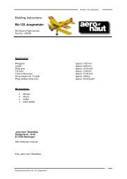
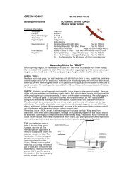
Hand-made Almost Ready to Fly R/C Model Aircraft<br />
ASSEMBLY MANUAL<br />
“Graphics and Specfications may change without notice”.<br />
Specifications<br />
Length---------------------------------122.3cm--------------- 48in.<br />
Wingspan-----------------------------160cm----------------- 63in.<br />
Wing area-----------------------------<strong>40</strong>47sp cm ---- 627sp in.<br />
Approximate flying weight--------2.8-2.95kg. --- 6.2-6.5lbs.<br />
Recommended engine size-----------------.<strong>40</strong>-.48 2-stroke.<br />
----------------.50-.72 4-stroke.<br />
Recommended R/C---------------- 4 channel With 5 servos.<br />
Flying skill level------------------------ advanced/Intermediate.<br />
Additional items required.<br />
Engine.<br />
4 Channel or greater Radio Control system.<br />
Glues.<br />
Tools.<br />
Starting Equipment.<br />
Kit features.<br />
• Ready-made-minimal assembly & finishing required.<br />
• Factory-installed pushrods.<br />
• Photo-illustrated step-by-step Assembly <strong>Manual</strong>.<br />
Made in Vietnam.
SPACE WALKER <strong>II</strong><br />
Instruction <strong>Manual</strong>.<br />
INTRODUCTION.<br />
Thank you for choosing the SPACE WALKER <strong>II</strong> ARTF by SEAGULL MODELS. The SPACE<br />
WALKER <strong>II</strong> was designed with the intermediate/advanced sport flyer in mind. It is a semi scale<br />
airplane which is easy to fly and quick to assemble. The airframe is conventionally built using balsa,<br />
plywood and veneer to make it stronger than the average ARTF , yet the design allows the aeroplane<br />
to be kept light. You will find that most of the work has been done for you already. The pushrods are<br />
pre-made to the correct lengths, the motor mount has been fitted and the hinges are pre-installed<br />
and pinned for security. Flying the SPACE WALKER <strong>II</strong> is simply a joy.<br />
This instruction manual is designed to help you build a great flying aeroplane. Please read this<br />
manual thoroughly before starting assembly of your SPACE WALKER <strong>II</strong> . Use the parts listing below<br />
to identify all parts.<br />
WARNING.<br />
Please be aware that this aeroplane is not a toy and if assembled or used incorrectly it is<br />
capable of causing injury to people or property. WHEN YOU FLY THIS AEROPLANE YOU<br />
ASSUME ALL RISK & RESPONSIBILITY.<br />
If you are inexperienced with basic R/C flight we strongly recommend you contact your R/C supplier<br />
and join your local R/C Model Flying Club. R/C Model Flying Clubs offer a variety of training<br />
procedures designed to help the new pilot on his way to successful R/C flight. They will also be able<br />
to advise on any insurance and safety regulations that may apply.<br />
ADDITIONAL ITEMS REQUIRED.<br />
<br />
<br />
<br />
<br />
<br />
<br />
<br />
.<strong>40</strong>-.48 2-stroke engine.<br />
.50-.72 4-stroke engine.<br />
4-channel radio with five servos.<br />
Glow plug to suit engine.<br />
Propeller to suit engine.<br />
Protective foam rubber for radio<br />
system.<br />
Silicone fuel line.<br />
Stick-on weights for balance.<br />
(If necessary)<br />
TOOLS & SUPPLIES NEEDED.<br />
<br />
<br />
<br />
<br />
<br />
<br />
<br />
<br />
<br />
<br />
<br />
<br />
<br />
<br />
Thick cyanoacrylate glue.<br />
30 minute epoxy.<br />
5 minute epoxy.<br />
Hand or electric drill.<br />
Assorted drill bits.<br />
Modelling knife.<br />
Straight edge ruler.<br />
2mm ball driver.<br />
Phillips head screwdriver.<br />
220 grit sandpaper.<br />
90° square or builder’s triangle<br />
Wire cutters.<br />
Masking tape & T-pins.<br />
Thread-lock.<br />
Paper towels.<br />
PARTS LISTING.<br />
FUSELAGE ASSEMBLY<br />
(1) Fuselage.<br />
(1) Pre-installed throttle pushrod &<br />
tube.<br />
(1) Pre-installed servo tray.<br />
(1) Pre-installed motor mount.<br />
(1) Pre-installed rudder pushrod.<br />
(1) Pre-installed elevator pushrod.<br />
WING ASSEMBLY<br />
(1) Right wing half with pre-installed<br />
aileron.<br />
(1) Left wing half with pre-installed<br />
aileron.<br />
(1) Plywood wing dihedral brace.<br />
(1) Covering strip for centre section<br />
joint.<br />
Tail section assembly<br />
(1) Vertical stabilizer with preinstalled<br />
rudder.<br />
(1) <strong>Horizon</strong>tal stabilizer with preinstalled<br />
elevator halves.<br />
Some more parts.<br />
2
SPACE WALKER <strong>II</strong><br />
INSTRUCTION MANUAL.<br />
NOTE: To avoid scratching your new aeroplane<br />
we suggest that you cover your<br />
workbench with an old towel. Keep a<br />
couple of jars or bowls handy to hold<br />
the small parts after you open the<br />
bags.<br />
Please trial fit all parts. Make sure you<br />
have the correct parts and that they fit<br />
and are aligned properly before gluing!<br />
This will ensure proper assembly as<br />
the Space Walker <strong>II</strong> is made from<br />
natural materials and minor adjustments<br />
may have to be made.<br />
The paint and plastic parts used in<br />
this kit are fuel proof. However, they<br />
are not tolerant of many harsh chemicals<br />
including the following: paint<br />
thinner, cyano-acrylate glue accelerator,<br />
cyanoacrylate glue de-bonder<br />
and acetone. Do not let these chemicals<br />
come in contact with the colours<br />
on the covering and the plastic parts.<br />
Hinge.<br />
3) Slide the aileron on the wing panel until<br />
there is only a slight gap. The hinge is now<br />
centered on the wing panel and aileron.<br />
Remove the T-pins and snug the aileron<br />
against the wing panel. A gap of 1/64” or less<br />
should be maintained between the wing panel<br />
and aileron.<br />
T-pins.<br />
HINGING THE AILERONS.<br />
Note: The control surfaces, including the<br />
ailerons, elevators, and rudder, are<br />
prehinged with hinges installed, but the<br />
hinges are not glued in place. It is<br />
imperative that you properly adhere the<br />
hinges in place per the steps that follow<br />
using a high-quality thin C/A glue.<br />
4) Deflect the aileron and completely<br />
saturate each hinge with thin C/A glue. The<br />
ailerons front surface should lightly contact the<br />
wing during this procedure. Ideally, when the<br />
hinges are glued in place, a 1/64” gap or less<br />
will be maintained throughout the lengh of the<br />
aileron to the wing panel hinge line.<br />
Note:<br />
The hinge is constructed of a special<br />
material that allows the C/A to wick or<br />
penetrate and distribute throughout the<br />
hinge, securely bonding it to the wood<br />
structure of the wing panel and aileron.<br />
1) Carefully remove the aileron from one of<br />
the wing panels. Note the position of the hinges.<br />
2) Remove each hinge from the wing panel<br />
and aileron and place a T-pin in the center of<br />
each hinge. Slide each hinge into the aileron<br />
until the T-pin is snug against the aileron. This<br />
will help ensure an equal amount of hinge is<br />
on either side of the hinge line when the aileron<br />
is mounted to the wing panel.<br />
C/A glue.<br />
3
SPACE WALKER <strong>II</strong><br />
Instruction <strong>Manual</strong>.<br />
5) Turn the wing panel over and deflect the<br />
aileron in the opposite direction from the<br />
opposite side. Apply thin C/A glue to each<br />
hinge, making sure that the C/A penetrates into<br />
both the aileron and wing panel.<br />
6) Using C/A remover/debonder and a paper<br />
towel, remove any excess C/A glue that may<br />
have accumulated on the wing or in the aileron<br />
hinge area.<br />
7) Repeat this process with the other wing<br />
panel, securely hinging the aileron in place.<br />
8) After both ailerons are securely hinged,<br />
firmly grasp the wing panel and aileron to<br />
make sure the hinges are securely glued and<br />
cannot be pulled out. Do this by carefully<br />
applying medium pressure, trying to separate<br />
the aileron from the wing panel. Use caution<br />
not to crush the wing structure.<br />
Apply epoxy glue.<br />
Glue the elevator hinges in place using the<br />
same tectniques used to hinge the ailerons.<br />
HINGING THE RUDDER.<br />
Glue the rudder hinges in place using the<br />
same tectniques used to hinge the ailerons.<br />
Note: Work the aileron up and down several<br />
times to “work in” the hinges and check<br />
for proper movement.<br />
Repeat the procedure for the other aileron<br />
servo.<br />
HINGING THE ELEVATORS.<br />
1) Carefully remove the elevator from one<br />
of the horizontal stabilizer panels. Note the<br />
position of the hinges.<br />
2) Remove each hinge from the horizontal<br />
stabilizer panel and elevator and place a T-pin<br />
in the center of each hinge. Slide each hinge<br />
into the elevator until the T-pin is snug against<br />
the elevator. This will help ensure an equal<br />
amount of hinge is on either side of the hinge<br />
line when the elevator is mounted to the<br />
horizontal stabilizer panel.<br />
WING ASSEMBLY.<br />
NOTE:We highly recommend using 30 minute<br />
epoxy as it is stronger and provides more<br />
working time, allowing the builder to properly<br />
align the parts. Using fast cure epoxy when<br />
joining the wing halves could result in the glue<br />
drying before the wing halves are aligned<br />
properly which may result in failure of the wing<br />
centre section during flight.<br />
1) Test fit the Wing tube into each wing half.<br />
The brace should slide in easily up to the<br />
centreline that you drew. If not, use 220 grit<br />
sandpaper with a sanding block and sand<br />
down the edges and ends of the brace until it<br />
fits properly.<br />
4
SPACE WALKER <strong>II</strong><br />
INSTRUCTION MANUAL.<br />
Wing tube.<br />
Masking tape.<br />
2) Remove the brace when satisfied with<br />
its fit ineach wing half. Coat both sides of one<br />
half of the dihedral brace with 30 minute epoxy.<br />
Next, pour some epoxy into the dihedral box in<br />
one wing panel. Make sure you cover the top<br />
and bottom as well as the sides of the dihedral<br />
brace. Use enough epoxy to fill any gaps.<br />
3) When the epoxy has cured, carefully<br />
remove the masking tape from the wing.<br />
4) Peel off the backing from the self adhesive<br />
covering strip. Apply the strip to the centre<br />
section of the wing starting from the bottom<br />
trailing edge. Wrap the strip all the way around<br />
the wing until it meets the trailing edge again.<br />
Trim off any excess strip.<br />
Epoxy<br />
Carefully slide the two wing halves together<br />
and firmly press them together, allowing the<br />
excess epoxy to run out. There should not be<br />
any gap in the wing halves. Use rubbing<br />
alcohol and a paper tower to clean up any<br />
excess epoxy.<br />
C/A glue.<br />
Remove covering.<br />
INSTALLING THE AILERON SERVOS.<br />
Thread.<br />
Small<br />
weight.<br />
Apply masking tape at the wing join to hold<br />
the wing halves together securely.<br />
Servos.<br />
5
SPACE WALKER <strong>II</strong><br />
Instruction <strong>Manual</strong>.<br />
1) Install the rubber grommets and brass<br />
collets onto the aileron servo. Test fit the<br />
servo into the aileron servo mount.<br />
Because the size of servos differ, you<br />
may need to adjust the size of the precut opening<br />
in the mount. The notch in the sides of the<br />
mount allow the servo lead to pass through.<br />
Secure the servos with the screws provided<br />
from your radio system.<br />
2) Temporarilly install the aileron servo into<br />
the servo mount, with the output shaft towards<br />
the leading edge of the wing. Drill<br />
1.5mm pilot holes through the mount. Remove<br />
the servo from the wing.<br />
Electric wire.<br />
3) Tie a weight such as the fuel tank pickup<br />
to a piece of string. Carefully feed the<br />
thread through the wing and out of the servo<br />
String.<br />
Thread.<br />
Small weight.<br />
String.<br />
5) Tape the servo lead to the wing to prevent<br />
it from falling back into the wing.<br />
Small weight.<br />
Plastic tape.<br />
Thread.<br />
6) Reinstall the servo into the servo mount<br />
and secure the servo inplace using the wood<br />
screws provided with you radio system.<br />
4) Attach servo lead to the aileron servo.<br />
Attach the string to the servo lead and carefully<br />
thread it though the wing. Once you have<br />
thread the lead throught the wing, remove the<br />
thread so it can use for the other servo lead.<br />
6
SPACE WALKER <strong>II</strong><br />
INSTRUCTION MANUAL.<br />
Repeat the procedure for the other wing<br />
half.<br />
AILERON LINKAGE.<br />
1) Using a ruler & pen to draw a straight<br />
line as below picture.<br />
4) Using a 1mm drill bit and the control<br />
horns as a guide, drill the mounting holes<br />
through the aileron halves.<br />
5) Mount the control horns by inserting the<br />
screws through the control horn bases and<br />
aileron halves, then into the mounting<br />
backplates. Do not overtighten the screws or<br />
the backplates may crush the wood.<br />
Pen.<br />
Straight line.<br />
6) Thread one nylon adjustable control horn<br />
onto each aileron control rod. Thread the<br />
horns on until they are flush with the ends of<br />
the control rods.<br />
7) With the aileron servo centered and the<br />
aileron even with the trailing edge of the wing<br />
attach the clevis to the control horn. Mark the<br />
control wire where it crosses the servo arm<br />
hole.<br />
2) Locate the two nylon control horns, two<br />
nylon control horn backplates and four<br />
machine screws.<br />
3) Position the aileron horn on the bottom<br />
side of aileron. The clevis attachment holes<br />
should be positioned over the hinge line.<br />
Pen.<br />
2mm X 20mm.<br />
Cut.<br />
Control Horn.<br />
Mounting Screws.<br />
Mounting Plate.<br />
8) Make a 90-degree bend at the mark and<br />
cut off the excess wire leaving 10mm past the<br />
bend.<br />
7
SPACE WALKER <strong>II</strong><br />
Instruction <strong>Manual</strong>.<br />
Wire keeper.<br />
FUEL TANK.<br />
Servo arm.<br />
9) Connect the linkage as shown and secure<br />
the control wire with a wire keeper.<br />
Repeat the procedure for the other aileron<br />
servo.<br />
Important: When the stopper assembly is<br />
installed in the tank, the top of the vent tube<br />
should rest just below the top surface of the<br />
tank. It should not touch the top of the tank.<br />
4) Test fit the stopper assembly into the<br />
tank. It may be necessary to remove some of<br />
the flashing around the tank opening using a<br />
modeling knife. If flashing is present, make<br />
sure none falls into the tank.<br />
5) With the stopper assembly in place,<br />
the weighted pickup should rest away from<br />
the rear of the tank and move freely inside the<br />
tank. The top of the vent tube should rest just<br />
below the top of the tank. It should not touch<br />
the top of the tank.<br />
6) When satisfied with the alignment of<br />
the stopper assembly tighten the 3mm x 20mm<br />
machine screw until the rubber stopper expands<br />
and seals the tank opening. Do not<br />
overtighten the assembly as this could cause<br />
the tank to split.<br />
INSTALLING THE STOPPER ASSEMBLY.<br />
1) Using a modeling knife, carefully cut off<br />
the rear portion of one of the 3 nylon tubes<br />
leaving 1/2” protruding from the rear of the<br />
stopper. This will be the fuel pick up tube.<br />
2) Using a modeling knife, cut one length of<br />
silicon fuel line. Connect one end of the line to<br />
the weighted fuel pickup and the other end to<br />
the nylon pickup tube.<br />
3) Carefully bend the second nylon tube up<br />
at a 45º angle. This tube is the vent tube. To<br />
set the angle of the vent tube use a lighter or<br />
heat gun to heat the tube (do not melt the tube).<br />
Attach the silicone fuel and pressure pipes<br />
to the tank. The lower pipe is the ‘feed’ and the<br />
upper two the ‘pressure and fill’. The fill pipe is<br />
the next pipe.<br />
Vent tube.<br />
Fuel pickup tube.<br />
Fuel fill tube.<br />
8
SPACE WALKER <strong>II</strong><br />
INSTRUCTION MANUAL.<br />
You should mark which tube is the vent<br />
and which is the fuel pickup when you<br />
attach fuel tubing to the tubes in the stopper.<br />
Once the tank is installed inside the fuselage,<br />
it may be difficult to determine which is which.<br />
Slide the tank into the fuselage from inside<br />
so that the neck is at the top of the fuselage<br />
and it locates through the engine bulkhead.<br />
Gently secure it to the top horizontal former<br />
with a cable tie.<br />
C/A glue attached.<br />
Fuel.<br />
11cm.<br />
2) Place your engine onto the engine mount.<br />
Adjust the engine is centered of the edges of<br />
the engine case.<br />
3) When you are satisfied with the alignment,<br />
mark the locations of the engine<br />
mounting.<br />
4) Remove the engine. Using an drill bit, drill<br />
the mounting holes through the engine mount<br />
at the four locations marked.<br />
2.5mm.<br />
Vent tube.<br />
Fuel pickup<br />
tube.<br />
Fuel fill tube.<br />
3mm X 25mm.<br />
5) Bolt the engine to the engine mount<br />
using the four machine screws. Double<br />
cheek that all the screws are tight before<br />
proceeding.<br />
Blow through one of the lines to ensure<br />
the fuel lines have not become kinked inside<br />
the fuel tank compartment. Air should<br />
flow through easily.<br />
6) Attach the Z-Bend in the pushrod wire to<br />
the throttle arm on the carburetor.<br />
MOUNTING THE ENGINE.<br />
1) Install the pushrod housing through the<br />
predrilled hole in the firewall and into the servo<br />
compartment. The pushrod housing should<br />
protrude 1/4" out past the front of the firewall.<br />
Make a Z-Bend 1/4" from one end of the plain<br />
wire pushrod.<br />
Pushrod wire.<br />
9
SPACE WALKER <strong>II</strong><br />
Instruction <strong>Manual</strong>.<br />
COWLING.<br />
1) Slide the fiberglass cowl over the engine<br />
and line up the back edge of the cowl with<br />
the marks you made on the fuselage.<br />
2) While keeping the back edge of the<br />
cowl flush with the marks, align the front of<br />
the cowl with the crankshaft of the engine. The<br />
front of the cowl should be positioned so the<br />
crankshaft is in the middle of the cowl opening.<br />
Hold the cowl firmly in place using pieces<br />
of masking tape.<br />
3) With the cowl held firmly in place, transfer<br />
the marks from the centerline of the blocks,<br />
that were drawn onto the fuselage previously,<br />
onto the cowl. Using a ruler and a pen, measure<br />
forward from the back edge of the cowl<br />
7/16”, at the four mounting block locations, and<br />
place a mark.<br />
Because of the diameter of the cowl, it<br />
may be necessary to use a needle valve<br />
extension for the high speed needle valve.<br />
Make this out of sufficient length 1.5mm wire<br />
and install it into the end of the needle valve.<br />
Secure the wire in place by tightening the set<br />
screw in the side of the needle valve.<br />
8) Install the muffler and muffler extension<br />
onto the engine and make the cutout in the<br />
cowl for muffler clearance. Connect the fuel<br />
and pressure lines to the carburetor, muffler<br />
and fuel filler valve.<br />
1.5 mm wire.<br />
4) While holding the cowl firmly in position,<br />
drill four 1/16” pilot holes through both the<br />
cowl and through the mounting fuselage.<br />
5) Remove the cowl. Using a 5/64” drill<br />
bit, enlarge the holes in only the four cowl<br />
blocks.<br />
6) Using a 1/8” drill bit. Enlarging the holes<br />
through the cowl will prevent the fiberglass<br />
from splitting when the mounting screws are<br />
installed.<br />
7) Slide the cowl back over the engine<br />
and secure it in place using four 3mm x 12mm<br />
wood screws.See picture below.<br />
INSTALLING THE SPINNER.<br />
1) Install the spinner backplate, propeller<br />
and spinner cone. The spinner cone is held in<br />
place using two 3mm x 12mm wood screws.<br />
The propeller should not touch any part<br />
of the spinner cone. If it does, use a sharp<br />
modeling knife and carefully trim away the<br />
spinner cone where the propeller comes in<br />
contact with it.<br />
4 wood screws<br />
3MM x 12MM.<br />
Spinner backplate.<br />
10
SPACE WALKER <strong>II</strong><br />
INSTRUCTION MANUAL.<br />
10mm.<br />
5mm.<br />
3) You have to trim each axle using a tool<br />
cutting and cut-off wheel.<br />
WHEEL AND WHEEL PANTS.<br />
1) Assemble and mounting the wheel pants<br />
as shown in the following pictures.<br />
Caution when cutting the axles and wear<br />
protective goggles.<br />
46mm.<br />
2) Follow diagram below for wheel pant<br />
installation:<br />
Wheel Collar.<br />
(2) Washer.<br />
Axle.<br />
Nut.<br />
Wheel.<br />
Nut.<br />
Landing Gear.<br />
(2) Wheel Collar.<br />
(2) Washer.<br />
Wheel Pant.<br />
Axle.<br />
Nut.<br />
Wheel.<br />
Nut.<br />
11
SPACE WALKER <strong>II</strong><br />
Instruction <strong>Manual</strong>.<br />
Landing gear.<br />
4mm X 20mm.<br />
HORIZONTAL STABILIZER.<br />
1) Using a ruler and a pen, locate the<br />
centerline of the horizontal stabilizer, at the trailing<br />
edge, and place a mark. Use a triangle<br />
and extend this mark, from back to front,<br />
across the top of the stabilizer. Also extend<br />
this mark down the back of the trailing edge of<br />
the stabilizer.<br />
Draw center line.<br />
2) Slide the stabilizer into place in the precut<br />
slot in the rear of the fuselage. The stabilizer<br />
should be pushed firmly against the front<br />
of the slot.<br />
4) A drop of C/A glue on the wheel collar<br />
screws will help keep them from coming lose<br />
during operation.<br />
Repeat the process for the other wheel.<br />
INSTALLING THE MAIN LANDING GEAR.<br />
1) The blind nuts are already mounted inside<br />
the fuselage.<br />
2) Using the hardware provided, mount the<br />
main landing gear to the fuselage.<br />
3) With the stabilizer held firmly in place,<br />
use a pen and draw lines onto the stabilizer<br />
where it and the fuselage sides meet. Do this<br />
on both the right and left sides and top and<br />
bottom of the stabilizer.<br />
12
SPACE WALKER <strong>II</strong><br />
INSTRUCTION MANUAL.<br />
Pen.<br />
4) Remove the stabilizer. Using the lines<br />
you just drew as a guide, carefully remove the<br />
covering from between them using a modeling<br />
knife.<br />
Remove covering.<br />
7) After the epoxy has fully cured, remove<br />
the masking tape or T-pins used to hold<br />
the stabilizer in place. Carefully inspect the<br />
glue joints. Use more epoxy to fill in any gaps<br />
that may exist that were not filled previously<br />
and clean up the excess using a paper towel<br />
and rubbing alcohol.<br />
VERTICAL STABILIZER<br />
INSTALLATION.<br />
When cutting through the covering to remove<br />
it, cut with only enough pressure<br />
to only cut through the covering itself. Cutting<br />
into the balsa structure may weaken it.<br />
5) Using a modeling knife, carefully remove<br />
the covering that overlaps the stabilizer<br />
mounting platform sides in the fuselage. Remove<br />
the covering from both the top and the<br />
bottom of the platform sides.<br />
6) When you are sure that everything is<br />
aligned correctly, mix up a generous amount<br />
of Flash 30 Minute Epoxy. Apply a thin layer to<br />
the top and bottom of the stabilizer mounting<br />
area and to the stabilizer mounting platform<br />
sides in the fuselage. Slide the stabilizer in<br />
place and realign. Double check all of your<br />
measurements once more before the epoxy<br />
cures. Hold the stabilizer in place with T-pins<br />
or masking tape and remove any excess epoxy<br />
using a paper towel and rubbing alcohol.<br />
1) Using a modeling knife, remove the<br />
covering from over the precut hinge slot cut<br />
into the lower rear portion of the fuselage. This<br />
slot accepts the lower rudder hinge.<br />
Hinge slot.<br />
13
SPACE WALKER <strong>II</strong><br />
Instruction <strong>Manual</strong>.<br />
2) Slide the vertical stabilizer into the slot<br />
in the top of the fuselage. The rear edge of<br />
the stabilizer should be flush with the rear edge<br />
of the fuselage and the lower rudder hinge<br />
should engage the precut hinge slot in the<br />
lower fuselage. The bottom edge of the stabilizer<br />
should also be firmly pushed against the<br />
top of the horizontal stabilizer.<br />
Remove covering.<br />
When cutting through the covering to remove<br />
it, cut with only enough pressure to only<br />
cut through the covering itself. Cutting into<br />
the balsa structure may weaken it.<br />
5) Slide the vertical stabilizer back in<br />
place. Using a triangle, check to ensure that<br />
the vertical stabilizer is aligned 90º to the horizontal<br />
stabilizer.<br />
3) While holding the vertical stabilizer<br />
firmly in place, use a pen and draw a line on<br />
each side of the vertical stabilizer where it<br />
meets the top of the fuselage.<br />
Pen.<br />
<strong>Horizon</strong>tal<br />
Stabilizer.<br />
Tail strut.<br />
90º<br />
Vertical<br />
Stabilizer.<br />
6) When you are sure that everything is<br />
aligned correctly, mix up a generous amount of<br />
Flash 30 Minute Epoxy. Apply a thin layer to<br />
the mounting slot in the top of the fuselage and<br />
to the sides and bottom of the vertical stabilizer<br />
mounting area. Apply epoxy to the bottom and<br />
top edges of the filler block and to the lower<br />
hinge also. Set the stabilizer in place and realign.<br />
Double check all of your measurements<br />
once more before the epoxy cures. Hold the<br />
stabilizer in place with T-pins or masking tape<br />
and remove any excess epoxy using a paper<br />
towel and rubbing alcohol. Allow the epoxy to<br />
fully cure before proceeding.<br />
4) Remove the stabilizer. Using a modeling<br />
knife, remove the covering from below the<br />
lines you drew. Also remove the covering from<br />
the bottom edge of the stabilizer and the bottom<br />
and top edges of the filler block. Leave<br />
the covering in place on the sides of the filler<br />
block.<br />
C/A glue.<br />
14
SPACE WALKER <strong>II</strong><br />
INSTRUCTION MANUAL.<br />
Rudder control horn.<br />
CONTROL HORN INSTALLTION.<br />
1)Elevator and rudder control horn in place<br />
using the same techinques to aleron control<br />
horn.See picture below.<br />
2) Position the elevator horns on the one<br />
side of elevator. The clevis attach- ment holes<br />
should be positioned over the hinge line.<br />
PUSHROD INSTALLATION.<br />
Elevator pushrod.<br />
2mm X 20mm.<br />
Control Horn.<br />
Rudder pushrod.<br />
Mounting Screws.<br />
Mounting Plate.<br />
MOUNTING THE CONTROL CLASP.<br />
3) Position the rudder control horn on the<br />
left side of the airplane.Mount the control horn<br />
parallel with the horizontal stabilizer.<br />
Elevator control<br />
horn.<br />
1) Align the tail wheel wire so that the wire<br />
is parallel with the bottom of the rudder. The<br />
control clasp has a predrilled hole through the<br />
top of it. Slide this hole onto the tail wheel wire<br />
while sliding the clasp over the bottom of the<br />
rudder.<br />
2) Using a ruler and a pen place a mark onto<br />
the bottom of the rudder. The back edge of<br />
the clasp should line up with this mark.You may<br />
find it necessary to bend the tail wheel wire<br />
down slightly so it lines up with the clasp without<br />
binding.<br />
15
SPACE WALKER <strong>II</strong><br />
Instruction <strong>Manual</strong>.<br />
3) While holding the clasp firmly in place,<br />
use a pen and outline the clasp onto the rudder.<br />
4) Remove the clasp, and using a modeling<br />
knife, remove the covering from inside the<br />
lines you drew. Use 220 grit sandpaper and<br />
carefully roughen the inside surface of the nylon<br />
clasp.<br />
5) Slide the clasp back into position and<br />
carefully glue it into place using Kwik Bond Thin<br />
C/A. Hold the clasp in place until the glue completely<br />
cures. Secure by 1 machine<br />
screw.<br />
Control clasp.<br />
INSTALLING THE SWITCH.<br />
1) Install the switch into the precut hole<br />
in the servo tray, in the fuselage, from the bottom.<br />
Use the two screws provided with the<br />
switch to secure it in place. Drill two 3/32”<br />
holes through the tray for the screws to pass<br />
through.<br />
2) Make a push-pull lever out of scrap<br />
wire. Attach the wire to the switch lever and<br />
route the wire out the side of the fuselage,<br />
through the hole you drilled.<br />
Some switches come with a hole drilled<br />
through the switch tab for this very purpose.<br />
If your switch does not, remove the<br />
switch and drill a 3/32” hole through the middle<br />
of the switch tab.<br />
Machine Screw<br />
2 MM x 12 MM.<br />
INSTALLING THE FUSELAGE SERVOS.<br />
3) Install the rubber grommets and brass<br />
collets onto the elevator, rudder and throttle<br />
servos. Test fit the servos into the preinstalled<br />
servo tray. Because the size of servos differ,<br />
you may need to adjust the size of the<br />
precut openings in the tray.<br />
Secure the servos with the screws provided<br />
from your radio system.<br />
4) Position the servos into the servo tray<br />
with the output shafts orientated as shown<br />
below. Drill 1/16” pilot holes through the tray<br />
for each of the mounting screws.<br />
Throttle.<br />
Rudder.<br />
Switch.<br />
Elevator.<br />
5) Install adjustable servo connector in<br />
the servo arm.<br />
16
SPACE WALKER <strong>II</strong><br />
INSTRUCTION MANUAL.<br />
Servo arm.<br />
Adjustable Servo<br />
connector.<br />
LANDING GEAR<br />
( 3 PCS).<br />
C/A glue.<br />
Thread locker glue.<br />
6) Connect the elevator, rudder and throttle<br />
servos to your radio’s receiver and turn on<br />
the system. Set the trim tabs on the transmitter<br />
to neutral and center the servo arms. The<br />
elevator, rudder and throttle servo arms should<br />
be perpendicular to the servos.<br />
7) One at a time, hold the pushrods in position<br />
over the respective servos to check for<br />
proper servo direction. If any servo turns in the<br />
wrong direction, switch your radio’s reversing<br />
switches as necessary to achieve the correct<br />
direction.<br />
8) Install servos arm to servos. Notice the<br />
position of the servo arms on the servos. See<br />
picture as below.<br />
INSTALLATION PILOT.<br />
INSTALLING THE RECEIVER AND BATTERY.<br />
1) Plug the five servo leads and the switch<br />
lead into the receiver. Plug the battery pack<br />
lead into the switch also.<br />
2) Wrap the receiver and battery pack in<br />
the protective foam rubber to protect them<br />
from vibration<br />
3) Position the battery pack in the fuel tank<br />
compartment and the receiver just behind the<br />
fuel tank . Use extra foam pieces to hold them<br />
in position.<br />
When balancing the airplane you may<br />
need to move the battery or receiver forward<br />
or after to achieve proper balance. In our<br />
test airplane, using a .46 two stroke engine,<br />
the battery and receiver were mounted as per<br />
step # 4.<br />
Silicon glue.<br />
52mm.<br />
52mm.<br />
17
SPACE WALKER <strong>II</strong><br />
Instruction <strong>Manual</strong>.<br />
When balanced correctly, the airplane should<br />
sit level or slightly nose down when you lift it<br />
up with your fingers.<br />
Silicon glue.<br />
2M x 8mm.<br />
10mm.<br />
10mm.<br />
7,5-8cm.<br />
CONTROL THROWS.<br />
ATTACHMENT WING - FUSELAGE.<br />
Bolt the wing to fuselage.<br />
Wing bolt.<br />
1) We highly recommend setting up the<br />
Space Walker <strong>II</strong> using the control throws listed<br />
at right. We have listed control throws for both<br />
initial test/sport flying and aerobatic flying.<br />
2) Turn on the radio system, and with the<br />
trim tabs on the transmitter in neutral, center<br />
the control surfaces by making adjustments<br />
to the clevises or adjustable servo connectors.<br />
The servo arms should be centered also.<br />
BALANCING.<br />
1) It is critical that your airplane be balanced<br />
correctly. Improper balance will cause your<br />
plane to lose control and crash. The center of<br />
gravity is located 7,5- 8cm back from the leading<br />
edge of the wing, measured at the wing<br />
tip.<br />
2) If the nose of the plane falls, the plane<br />
is nose heavy. To correct this first move the<br />
battery pack further back in the fuselage. If<br />
this is not possible or does not correct it, stick<br />
small amounts of lead weight on the fuselage<br />
sides under the horizontal stabilizer. If the tail<br />
of the plane falls, the plane is tail heavy. To<br />
correct this, move the battery and receiver forward<br />
or if this is not possible, stick weight onto<br />
the firewall or use a brass heavy hub spinner<br />
hub.<br />
3) When the elevator, rudder and aileron<br />
control surfaces are centered, use a ruler and<br />
check the amount of the control throw in each<br />
surface. The control throws should be<br />
measured at the widest point of each surface!<br />
INITIAL FLYING/SPORT FLYING<br />
Ailerons: 3/16” up 3/16” down.<br />
Elevator: 3/8” up 3/8” down.<br />
Rudder: 1” right 1” left.<br />
AEROBATIC FLYING<br />
Ailerons: 3/8” up 3/8” down.<br />
Elevator: 1” up 1” down.<br />
Rudder: 2” right 2” left.<br />
Do not use the aerobatic settings for<br />
initial test flying or sport flying.<br />
18
SPACE WALKER <strong>II</strong><br />
INSTRUCTION MANUAL.<br />
4) By moving the position of the adjustable<br />
control horn out from the control surface,<br />
you will decrease the amount of throw of that<br />
control surface. Moving the adjustable control<br />
horn toward the control surface will increase<br />
the amount of throw.<br />
FLIGHT PREPARATION.<br />
1) Check the operation and direction of<br />
the elevator, rudder, ailerons and throttle.<br />
A) Plug in your radio system per the<br />
manufacturer's instructions and turn everything<br />
on.<br />
B) Check the elevator first. Pull back on<br />
the elevator stick. The elevator halves should<br />
move up. If it they do not, flip the servo reversing<br />
switch on your transmitter to change<br />
the direction.<br />
C) Check the rudder. Looking from behind<br />
the airplane, move the rudder stick to the<br />
right. The rudder should move to the right. If it<br />
does not, flip the servo reversing switch on<br />
your transmitter to change the direction.<br />
D) Check the throttle. Moving the throttle<br />
stick forward should open the carburetor barrel.<br />
If it does not, flip the servo reversing switch<br />
on your transmitter to change the direction.<br />
E) From behind the airplane, look at the<br />
aileron on the right wing half. Move the aileron<br />
stick to the right. The right aileron should move<br />
up and the other aileron should move down. If<br />
it does not, flip the servo reversing switch on<br />
your transmitter to change the direction.<br />
2) Check Control Surface Throw.<br />
A) The Rudder should move 1” left and<br />
1” right from center. If it moves too far, turn<br />
the adjustable control horn out away from the<br />
rudder. Do the opposite if there is not enough<br />
throw.<br />
B) Both elevator halves should move 3/<br />
8” up and 3/8” down from center. If they move<br />
too far, turn the adjustable control horns out<br />
away from the elevator halves. Do the opposite<br />
if there is not enough throw. Both elevator<br />
halves should also travel the same amount<br />
throughout their total movement.<br />
C)The ailerons should move 3/16” up and<br />
3/16” down from center. If the ailerons<br />
move too much, turn the adjustable control<br />
horns out away from the wing. Do the opposite<br />
if there is not enough throw. It is important<br />
that both ailerons move the same amount,<br />
both up and down.<br />
D) Once the control throws and movements<br />
are set, tubing must be added to the<br />
clevises to ensure they do not release in the<br />
air. Cut a piece of fuel line into five 1/4” long<br />
pieces. Unsnap the clevises and slip one<br />
piece over each clevis. Snap the clevises back<br />
in place and slide the tubing up over them.<br />
PREFLIGHT CHECK.<br />
1) Completely charge your transmitter<br />
and receiver batteries before your first day of<br />
flying.<br />
2) Check every bolt and every glue joint<br />
in the Space Walker <strong>II</strong> to ensure that everything<br />
is tight and well bonded.<br />
3) Double check the balance of the airplane.<br />
Do this with the fuel tank empty.<br />
4) Check the control surfaces. All should<br />
move in the correct direction and not bind in<br />
any way.<br />
5) If your radio transmitter is equipped with<br />
dual rate switches double check that they are<br />
on the low rate setting for your first few flights.<br />
6) Check to ensure the control surfaces are<br />
moving the proper amount for both low and<br />
high rate settings.<br />
7) Check the receiver antenna. It should be<br />
fully extended and not coiled up inside the fuselage.<br />
8) Properly balance the propeller. An out of<br />
balance propeller will cause excessive vibration<br />
which could lead to engine and/or airframe<br />
failure.<br />
We wish you many safe and enjoyable<br />
flights with your Space Walker <strong>II</strong>.<br />
19
SPACE WALKER <strong>II</strong><br />
Instruction <strong>Manual</strong>.<br />
FOR USA MARKET ONLYLY.<br />
Warranty Period:<br />
Exclusive Warranty- <strong>Horizon</strong> <strong>Hobby</strong>, Inc., (<strong>Horizon</strong>) warranties that the Products purchased (the “Product”)<br />
will be free from defects in materials and workmanship at the date of purchase by the Purchaser.<br />
Limited Warranty<br />
(a) This warranty is limited to the original Purchaser (“Purchaser”) and is not transferable. REPAIR OR REPLACEMENT<br />
AS PROVIDED UNDER THIS WARRANTY IS THE EXCLUSIVE REMEDY OF THE PURCHASER. This warranty<br />
covers only those Products purchased from an authorized <strong>Horizon</strong> dealer. Third party transactions are not covered<br />
by this warranty. Proof of purchase is required for warranty claims. Further, <strong>Horizon</strong> reserves the right to change or<br />
modify this warranty without notice and disclaims all other warranties, express or implied.<br />
(b) Limitations- HORIZON MAKES NO WARRANTY OR REPRESENTATION, EXPRESS OR IMPLIED, ABOUT NON-<br />
INFRINGEMENT, MERCHANTABILITY OR FITNESS FOR A PARTICULAR PURPOSE OF THE PRODUCT. THE<br />
PURCHASER ACKNOWLEDGES THAT THEY ALONE HAVE DETERMINED THAT THE PRODUCT WILL SUITABLY<br />
MEET THE<br />
REQUIREMENTS OF THE PURCHASER’S INTENDED USE.<br />
(c) Purchaser Remedy- <strong>Horizon</strong>’s sole obligation hereunder shall be that <strong>Horizon</strong> will, at its option, (i) repair or (ii)<br />
replace, any Product determined by <strong>Horizon</strong> to be defective. In the event of a defect, these are the Purchaser’s<br />
exclusive remedies. <strong>Horizon</strong> reserves the right to inspect any and all equipment involved in a warranty claim. Repair<br />
or replacement decisions are at the sole discretion of <strong>Horizon</strong>. This warranty does not cover cosmetic damage or<br />
damage due to acts of God, accident, misuse, abuse, negligence, commercial use, or modification of or to any part<br />
of the Product. This warranty does not cover damage due to improper installation, operation, maintenance, or<br />
attempted repair by anyone other than <strong>Horizon</strong>. Return of any goods by Purchaser must be approved in writing by<br />
<strong>Horizon</strong> before shipment.<br />
Damage Limits:<br />
HORIZON SHALL NOT BE LIABLE FOR SPECIAL, INDIRECT OR CONSEQUENTIAL DAMAGES, LOSS OF PROFITS<br />
OR PRODUCTION OR COMMERCIAL LOSS IN ANY WAY CONNECTED WITH THE PRODUCT, WHETHER SUCH<br />
CLAIM IS BASED IN CONTRACT, WARRANTY, NEGLIGENCE, OR STRICT LIABILITY. Further, in no event shall the<br />
liability of <strong>Horizon</strong> exceed the individual price of the Product on which liability is asserted. As <strong>Horizon</strong> has no control<br />
over use, setup, final assembly, modification or misuse, no liability shall be assumed nor accepted for any resulting<br />
damage or injury. By the act of use, setup or assembly, the user accepts all resulting liability.<br />
If you as the Purchaser or user are not prepared to accept the liability associated with the use of this Product, you are<br />
advised to return this Product immediately in new and unused condition to the place of purchase.<br />
Law: These Terms are governed by Illinois law (without regard to conflict of law principals).<br />
Safety Precautions:<br />
This is a sophisticated hobby Product and not a toy. It must be operated with caution and common sense and<br />
requires some basic mechanical ability. Failure to operate this Product in a safe and responsible manner could<br />
result in injury or damage to the Product or other property. This Product is not intended for use by children without<br />
direct adult supervision. The Product manual contains instructions for safety, operation and maintenance. It is<br />
essential to read and follow all the instructions and warnings in the manual, prior to assembly, setup or use, in<br />
order to operate correctly and avoid damage or injury.<br />
Questions, Assistance, and Repairs:<br />
Your local hobby store and/or place of purchase cannot provide warranty support or repair. Once assembly, setup or<br />
use of the Product has been started, you must contact <strong>Horizon</strong> directly. This will enable <strong>Horizon</strong> to better answer<br />
your questions and service you in the event that you may need any assistance. For questions or assistance, please<br />
direct your email to productsupport@horizonhobby.com, or call 877.504.0233 toll free to speak to a service technician.<br />
Inspection or Repairs<br />
If this Product needs to be inspected or repaired, please call for a Return Merchandise Authorization (RMA). Pack the<br />
Product securely using a shipping carton. Please note that original boxes may be included, but are not designed to<br />
withstand the rigors of shipping without additional protection. Ship via a carrier that provides tracking and insurance<br />
for lost or damaged parcels, as <strong>Horizon</strong> is not responsible for merchandise until it arrives and is accepted at our<br />
facility. A Service Repair Request is available at www.horizonhobby.com on the “Support” tab. If you do not have<br />
internet access, please include a letter with your complete name, street address, email address and phone<br />
number where you can be reached during business days, your RMA number, a list of the included items, method of<br />
payment for any non-warranty expenses and a brief summary of the problem. Your original sales receipt must also<br />
be included for warranty consideration. Be sure your name, address, and RMA number are clearly written on the<br />
outside of the shipping carton.<br />
20
SPACE WALKER <strong>II</strong><br />
INSTRUCTION MANUAL.<br />
Warranty Inspection and Repairs<br />
To receive warranty service, you must include your original sales receipt verifying the proof-of-purchase date.<br />
Provided warranty conditions have been met, your Product will be repaired or replaced free of charge. Repair or<br />
replacement decisions are at the sole discretion of <strong>Horizon</strong> <strong>Hobby</strong>.<br />
Non-Warranty Repairs<br />
Should your repair not be covered by warranty the repair will be completed and payment will be required<br />
without notification or estimate of the expense unless the expense exceeds 50% of the retail purchase cost. By<br />
submitting the item for repair you are agreeing to payment of the repair without notification. Repair estimates are<br />
available upon request. You must include this request with your repair. Non-warranty repair estimates will be billed<br />
a minimum of ½ hour of labor. In addition you will be billed for return freight. Please advise us of your preferred<br />
method of payment. <strong>Horizon</strong> accepts money orders and cashiers checks, as well as Visa, MasterCard, American<br />
Express, and Discover cards. If you choose to pay by credit card, please include your credit card number and<br />
expiration date. Any repair left unpaid or unclaimed after 90 days will be considered abandoned and will be disposed<br />
of accordingly. Please note: non-warranty repair is only available on electronics and model engines.<br />
Electronics and engines requiring inspection or repair should be shipped to the following address:<br />
<strong>Horizon</strong> Service Center<br />
4105 Fieldstone Road<br />
Champaign, Illinois 61822<br />
All other Products requiring warranty inspection or repair should be shipped to the following address:<br />
<strong>Horizon</strong> Product Support<br />
4105 Fieldstone Road<br />
Champaign, Illinois 61822<br />
Please call 877-504-0233 with any questions or concerns regarding this product or warranty.<br />
21
SPACE WALKER <strong>II</strong><br />
Instruction <strong>Manual</strong>.<br />
22 The pictures and parts shown above should be changed