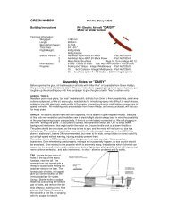
Spacewalker II 40 Manual - Horizon Hobby
Spacewalker II 40 Manual - Horizon Hobby
Spacewalker II 40 Manual - Horizon Hobby

You also want an ePaper? Increase the reach of your titles
YUMPU automatically turns print PDFs into web optimized ePapers that Google loves.
SPACE WALKER <strong>II</strong><br />
Instruction <strong>Manual</strong>.<br />
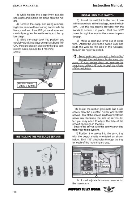
3) While holding the clasp firmly in place,<br />
use a pen and outline the clasp onto the rudder.<br />
4) Remove the clasp, and using a modeling<br />
knife, remove the covering from inside the<br />
lines you drew. Use 220 grit sandpaper and<br />
carefully roughen the inside surface of the nylon<br />
clasp.<br />
5) Slide the clasp back into position and<br />
carefully glue it into place using Kwik Bond Thin<br />
C/A. Hold the clasp in place until the glue completely<br />
cures. Secure by 1 machine<br />
screw.<br />
Control clasp.<br />
INSTALLING THE SWITCH.<br />
1) Install the switch into the precut hole<br />
in the servo tray, in the fuselage, from the bottom.<br />
Use the two screws provided with the<br />
switch to secure it in place. Drill two 3/32”<br />
holes through the tray for the screws to pass<br />
through.<br />
2) Make a push-pull lever out of scrap<br />
wire. Attach the wire to the switch lever and<br />
route the wire out the side of the fuselage,<br />
through the hole you drilled.<br />
Some switches come with a hole drilled<br />
through the switch tab for this very purpose.<br />
If your switch does not, remove the<br />
switch and drill a 3/32” hole through the middle<br />
of the switch tab.<br />
Machine Screw<br />
2 MM x 12 MM.<br />
INSTALLING THE FUSELAGE SERVOS.<br />
3) Install the rubber grommets and brass<br />
collets onto the elevator, rudder and throttle<br />
servos. Test fit the servos into the preinstalled<br />
servo tray. Because the size of servos differ,<br />
you may need to adjust the size of the<br />
precut openings in the tray.<br />
Secure the servos with the screws provided<br />
from your radio system.<br />
4) Position the servos into the servo tray<br />
with the output shafts orientated as shown<br />
below. Drill 1/16” pilot holes through the tray<br />
for each of the mounting screws.<br />
Throttle.<br />
Rudder.<br />
Switch.<br />
Elevator.<br />
5) Install adjustable servo connector in<br />
the servo arm.<br />
16