Spacewalker II 40 Manual - Horizon Hobby
Spacewalker II 40 Manual - Horizon Hobby
Spacewalker II 40 Manual - Horizon Hobby

Create successful ePaper yourself
Turn your PDF publications into a flip-book with our unique Google optimized e-Paper software.
SPACE WALKER <strong>II</strong><br />
Instruction <strong>Manual</strong>.<br />
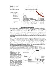
Wire keeper.<br />
FUEL TANK.<br />
Servo arm.<br />
9) Connect the linkage as shown and secure<br />
the control wire with a wire keeper.<br />
Repeat the procedure for the other aileron<br />
servo.<br />
Important: When the stopper assembly is<br />
installed in the tank, the top of the vent tube<br />
should rest just below the top surface of the<br />
tank. It should not touch the top of the tank.<br />
4) Test fit the stopper assembly into the<br />
tank. It may be necessary to remove some of<br />
the flashing around the tank opening using a<br />
modeling knife. If flashing is present, make<br />
sure none falls into the tank.<br />
5) With the stopper assembly in place,<br />
the weighted pickup should rest away from<br />
the rear of the tank and move freely inside the<br />
tank. The top of the vent tube should rest just<br />
below the top of the tank. It should not touch<br />
the top of the tank.<br />
6) When satisfied with the alignment of<br />
the stopper assembly tighten the 3mm x 20mm<br />
machine screw until the rubber stopper expands<br />
and seals the tank opening. Do not<br />
overtighten the assembly as this could cause<br />
the tank to split.<br />
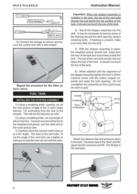
INSTALLING THE STOPPER ASSEMBLY.<br />
1) Using a modeling knife, carefully cut off<br />
the rear portion of one of the 3 nylon tubes<br />
leaving 1/2” protruding from the rear of the<br />
stopper. This will be the fuel pick up tube.<br />
2) Using a modeling knife, cut one length of<br />
silicon fuel line. Connect one end of the line to<br />
the weighted fuel pickup and the other end to<br />
the nylon pickup tube.<br />
3) Carefully bend the second nylon tube up<br />
at a 45º angle. This tube is the vent tube. To<br />
set the angle of the vent tube use a lighter or<br />
heat gun to heat the tube (do not melt the tube).<br />
Attach the silicone fuel and pressure pipes<br />
to the tank. The lower pipe is the ‘feed’ and the<br />
upper two the ‘pressure and fill’. The fill pipe is<br />
the next pipe.<br />
Vent tube.<br />
Fuel pickup tube.<br />
Fuel fill tube.<br />
8