Building instructions Pober Pixie - aero-naut Modellbau
Building instructions Pober Pixie - aero-naut Modellbau
Building instructions Pober Pixie - aero-naut Modellbau

Create successful ePaper yourself
Turn your PDF publications into a flip-book with our unique Google optimized e-Paper software.
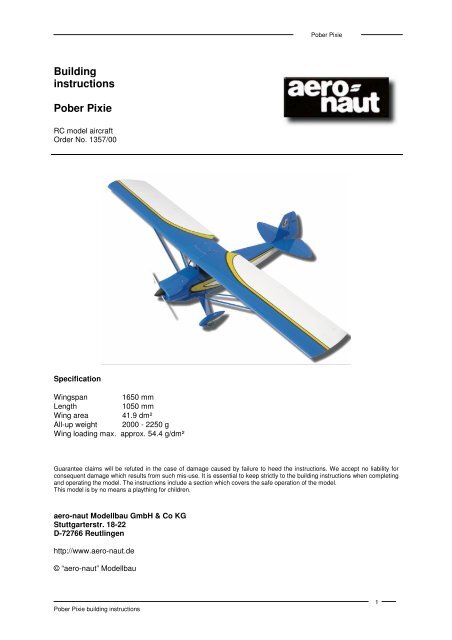
<strong>Pober</strong> <strong>Pixie</strong><br />
<strong>Building</strong><br />
<strong>instructions</strong><br />
<strong>Pober</strong> <strong>Pixie</strong><br />
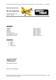
RC model aircraft<br />
Order No. 1357/00<br />
Specification<br />
Wingspan 1650 mm<br />
Length<br />
1050 mm<br />
Wing area 41.9 dm²<br />
All-up weight 2000 - 2250 g<br />
Wing loading max. approx. 54.4 g/dm²<br />
Guarantee claims will be refuted in the case of damage caused by failure to heed the <strong>instructions</strong>. We accept no liability for<br />
consequent damage which results from such mis-use. It is essential to keep strictly to the building <strong>instructions</strong> when completing<br />
and operating the model. The <strong>instructions</strong> include a section which covers the safe operation of the model.<br />
This model is by no means a plaything for children.<br />
<strong>aero</strong>-<strong>naut</strong> <strong>Modellbau</strong> GmbH & Co KG<br />
Stuttgarterstr. 18-22<br />
D-72766 Reutlingen<br />
http://www.<strong>aero</strong>-<strong>naut</strong>.de<br />
© “<strong>aero</strong>-<strong>naut</strong>” <strong>Modellbau</strong><br />
<strong>Pober</strong> <strong>Pixie</strong> building <strong>instructions</strong><br />
1
<strong>Pober</strong> <strong>Pixie</strong><br />
Contents<br />
Accessories required to build the model: ................................................................................................ 2<br />
Introductory notes.................................................................................................................................... 2<br />
Fuselage.................................................................................................................................................. 3<br />
Wing strut supports.................................................................................................................................. 3<br />
Undercarriage.......................................................................................................................................... 3<br />
Tailplane and fin ...................................................................................................................................... 4<br />
Installing the servos and “snakes”........................................................................................................... 5<br />
Wings....................................................................................................................................................... 5<br />
Wing struts............................................................................................................................................... 6<br />
Wing centre section ................................................................................................................................. 6<br />
Covering the wings .................................................................................................................................. 7<br />
Cowl......................................................................................................................................................... 7<br />
Installing the motor .................................................................................................................................. 7<br />
Recommended power set:....................................................................................................................... 8<br />
RC installation, finishing .......................................................................................................................... 9<br />
Recommended control surface travels.................................................................................................... 9<br />
Balancing................................................................................................................................................. 9<br />
Test-flying ................................................................................................................................................ 9<br />
Dangers and hazards ............................................................................................................................ 10<br />
Parts List................................................................................................................................................ 10<br />
Our model of the <strong>Pober</strong> <strong>Pixie</strong> represents a semi-scale version of the amateur design which was drawn<br />
up by Paul <strong>Pober</strong>ezny (founder and president of the EAA - Experimental Aircraft Association). The fullsize<br />
<strong>Pober</strong> <strong>Pixie</strong> is intended for anyone who wishes to own a low-priced machine which is simple to<br />
handle. The design emphasises good flying characteristics as well as low costs.<br />
The full-size machine is powered by engines rated at around 60 BHP (Continental A-64, fuel<br />
consumption approximately three gallons per hour).<br />
Today these aircraft are built and flown in the USA and other countries; every year the members of the<br />
“<strong>Pober</strong> <strong>Pixie</strong> Association” meet up at the flying event at Oshkosh, USA.<br />
Our model retains all the good qualities of the full-size machine, and its large wing area and powerful<br />
ailerons offer good manoeuvrability and excellent flying characteristics even at low airspeeds. The<br />
<strong>Pober</strong> <strong>Pixie</strong> represents an excellent choice for the beginner to flying.<br />
The kit contains a GRP fuselage and ready-built, uncovered wing panels, tailplane and fin. The model<br />
can therefore be completed ready for flying in a very short time, or alternatively can be fitted out to<br />
good “scale” standards if the builder prefers.<br />
The model was designed from the outset for electric power - the building <strong>instructions</strong> include<br />
suggestions for recommended power systems.<br />
Accessories required to build the model:<br />
Balsa knife, steel straight edge, ruler, white glue, screwdriver, 5-minute epoxy, thixotropic filler for<br />
thickening epoxy (optional), cyano-acrylate glue (“cyano”), abrasive paper, modelling pins, covering<br />
material (Oracover, Solarfilm), general modelling tools.<br />
Items required to fly the model:<br />
Motor, propeller, propeller driver, speed controller, connecting leads, connector system, RC<br />
equipment, four servos (special high-power or digital servos are not required).<br />
Introductory notes<br />
Please handle all the balsa components with care.<br />
The fuselage structure is adequately strong and resistant to vibration. Nevertheless it is important to<br />
install the individual components in the fuselage in approximately the positions shown.<br />
<strong>Pober</strong> <strong>Pixie</strong> building <strong>instructions</strong><br />
2
<strong>Pober</strong> <strong>Pixie</strong><br />
Sand the internal surfaces of the GRP fuselage moulding with abrasive paper (150-grit to 180-grit) to<br />
provide a “key” for the adhesive before gluing any component to it.<br />
Trial-fit and trim all parts carefully before reaching for the glue bottle.<br />
Epoxy is heavy; when using this adhesive for glued joints take care to use the absolute minimum. It is<br />
sometimes advisable to thicken the resin with micro-balloons. Read the <strong>instructions</strong> supplied by the<br />
adhesive manufacturer.<br />
Avoid sharp corners and edges when cutting out the openings in the fuselage. Reinforce cut edges by<br />
gluing glass rovings or pieces of plywood on the inside.<br />
Save weight wherever possible, especially at the tail end (tailplane and fin).<br />
As an alternative to epoxy you can use PU (polyurethane) adhesive such as ISOLEMFI 3300 (made<br />
by EMFI) or Sikaflex 252 to glue components to the GRP parts. PU glues are very simple to use<br />
because they are thixotropic (do not run) and harden without problem. PU foaming adhesives can also<br />
be used.<br />
Before painting the fuselage it is essential to de-grease the surfaces and carefully rub down the joint<br />
lines using 400-grit wet-and-dry paper, used wet.<br />
Fuselage<br />
Wing strut supports<br />
• Prepare the openings for the laminated wing strut supports as shown in the fuselage drawing.<br />
A recess is moulded into the fuselage at the support location - drill through the fuselage at the<br />
support position and cut the opening to final size using a milling cutter or a file. Check that the<br />
openings are the same size and in the same position on both sides.<br />
• The laminated strut supports are supplied with accurate holes for clevis-type strut ends. All<br />
you need to do is clean up the edges and round off the ends.<br />
• Centre the strut supports relative to the fuselage centreline, and tack them in place lightly<br />
using cyano. They are eventually glued in place permanently using epoxy, but not until the<br />
undercarriage mounting has been installed.<br />
Tip: apply the cyano glue in the centre of the fuselage to avoid the adhesive running onto the outside<br />
surface of the fuselage and spoiling its appearance. If this should happen, wipe off the excess using<br />
cyano cleaner.<br />
Undercarriage<br />
Main undercarriage<br />
• The main undercarriage unit is made of dural and features pre-drilled mounting holes. Section A-A<br />
shows the method of attaching the undercarriage - it is held in place by two M5 screws fitted from<br />
the outside.<br />
• Trim the plywood undercarriage support #1 to fit snugly in the fuselage. Cut lightening holes in the<br />
support, but take care to avoid the area of the holes for the retaining nuts. Glue the plywood<br />
support in place.<br />
• Place the undercarriage unit on the fuselage, align it carefully relative to the fuselage centreline<br />
and drill the 5 mm Ø holes through the fuselage. Remove the undercarriage again.<br />
• Glue the reinforcing plates #3 (3 mm plywood, 15 x 15 mm) to the undercarriage support over the<br />
screw holes.<br />
• Allow the glue to harden, then drill 8 mm Ø holes in the plates and epoxy the plastic nuts in the<br />
holes.<br />
Tip: screw the undercarriage to the fuselage while the epoxy is still soft, so that the screws hold<br />
the plastic nuts in the correct position.<br />
• De-grease the undercarriage unit and sand the central area. Place the balsa block #10 on the<br />
undercarriage, mark the position of the holes and drill them. Note: the balsa block is tapered so<br />
that it fits accurately in the prepared channel; it will only fit one way round.<br />
• Enlarge the holes in the balsa in-fill piece so that the heads of the M5 retaining screws rest on the<br />
metal itself.<br />
• Glue the balsa block #10 to the central part of the cleaned and sanded undercarriage unit.<br />
• Place this assembly on the fuselage. Apply masking tape to the fuselage to prevent it picking up<br />
scratches, then sand the balsa block so that it follows the lines of the fuselage.<br />
Tip: apply sanding sealer and primer to the balsa parts before painting the model.<br />
<strong>Pober</strong> <strong>Pixie</strong> building <strong>instructions</strong><br />
3
<strong>Pober</strong> <strong>Pixie</strong><br />
Wheel spats<br />
The wheel spats are supplied as vacuum-moulded ABS parts; see drawing (DET. 5).<br />
• Cut out the spat components along the marked lines, sand the cut edges carefully and trim the<br />
parts to fit together accurately - you will find the material is easy to cut and sand.<br />
• Cut out the opening for the wheel in each wheel spat and check that the wheel spigots fit.<br />
• Assemble the wheels and spigots as shown in the drawing (DET. 5), place them in the spats and<br />
glue the trimmed outer spat shell in place with cyano.<br />
• The method of attaching the wheel spats is shown in the drawing (DET. 5).<br />
• The spat assemblies can easily be fitted and screwed to the undercarriage unit after they have<br />
been filled and painted.<br />
Tailwheel unit<br />
• Sand the tailwheel support #4 (channeled part) to follow the shape of the fuselage as shown in the<br />
drawing, and glue it in place.<br />
• Cut through the fuselage using a razor blade to expose the channel, and fit the tailwheel unit in the<br />
slot.<br />
• Drill two 2 mm Ø holes at the marked points in the tailwheel unit to accept the 2.5 x 12 mm<br />
woodscrews.<br />
• The tailwheel unit can be glued and screwed in place permanently once the final finish has been<br />
applied.<br />
• We recommend that you install a steerable tailwheel as shown in the drawing (DET. 1): make up<br />
the guide (wire loop) and install it in the rudder after it has been covered.<br />
• Cut the steerable tailwheel “snake” to length and run it through the prepared guide (loop).<br />
Tailplane and fin<br />
Horizontal stabiliser - tailplane and elevators<br />
The tailplane is made of balsa and can now be prepared for installation. The same applies to the<br />
elevators, which are attached using film hinges.<br />
• Assemble the tailplane and elevators on a flat surface and place the joiner in position.<br />
• Drill holes for the elevator joiner in the elevators, taking care to space the holes to match the exact<br />
length of the joiner - see drawing (DET. 2).<br />
• Sand the tailplane / elevator panels lightly overall, wipe off all dust and cover them with iron-on<br />
film.<br />
• If you wish to use the covering film as the elevator hinge (see DET. 3), this is the procedure:<br />
o Prepare a strip of film slightly longer than the tailplane and elevators.<br />
o Cover the top surface of the tailplane and elevators.<br />
o Lay the tailplane on the workbench and fold the elevators up and over onto the tailplane.<br />
o Iron the strip of film to the underside of the elevators (position the elevators carefully<br />
beforehand - align them with the outside edge of the tailplane).<br />
o Cut off the film at the ends using a very sharp knife (use a steel straight edge).<br />
o<br />
o<br />
Turn the tailplane and elevators over and cover the underside.<br />
Again cut off the film accurately at the ends, leaving it overhanging by about 5 mm. Carefully<br />
iron down the edges.<br />
• Carefully pierce the film at the joiner hole positions and glue the steel joiner in both elevators.<br />
• Alternative elevator control linkage: prepare two steel rods with a 90° bend (see DET. 4) and fit<br />
them in the elevators with the angled rods located inside the fuselage. Solder the rods together<br />
and attach a linkage ball to accept the elevator ball-link.<br />
• This option is rather tricky, and should only be attempted if you are a competent, accurate builder.<br />
• Place the tailplane on the fuselage and position it accurately, i.e. “square” to the fuselage centreline<br />
and lateral axis, as shown in the drawing.<br />
Tip: use a length of thread to check that it is square relative to the fuselage centreline - attach one<br />
end to the centre of the cabane; the distance to both tailplane tips should be identical.<br />
• Use a soft pencil to draw a light mark on the underside of the tailplane where it meets the<br />
fuselage. Remove the tailplane, slit the film with a sharp knife and peel it away about 5 mm from<br />
the edge of the fuselage, so that the joint surface is bare wood; the film should overhang the joint<br />
area by about 5 mm. This ensures a strong, resilient glued joint.<br />
<strong>Pober</strong> <strong>Pixie</strong> building <strong>instructions</strong><br />
4
<strong>Pober</strong> <strong>Pixie</strong><br />
• Slit and peel off a strip of film about 10 - 15 mm wide in the centre of the top surface in the same<br />
manner (for attaching the fin and strake).<br />
• Cyano glue can also be applied directly to the film. In this case it is important to sand the joint line<br />
carefully and to apply the glue very accurately, because cyano behaves differently to epoxy, and<br />
the glued joint may fail after a shock.<br />
• Carefully replace the tailplane on the fuselage and epoxy the parts together.<br />
Vertical stabiliser - fin and rudder<br />
• The fin and strake are made of balsa and sanded. They are prepared for installation, including<br />
two slots for hinges. The strake consists of two parts.<br />
• Offer up the strake to the tailplane (attached to the fuselage) and sand it to fit accurately. Glue the<br />
strake to the fin. Sand this assembly smooth, taking care to shape the leading edge as shown.<br />
• Check that the assembly fits neatly on the fuselage, then cover the fin and strake with film.<br />
• Be sure to leave a strip of bare wood about 5 mm wide at the bottom of the fin on both sides.<br />
• Glue the covered fin assembly in place, taking care to set it exactly vertical relative to the<br />
tailplane, and in line with the fuselage centreline.<br />
• Cut the 8 x 8 mm triangular bracing strips to length (DET. 6) and trim them to fit. Cover the<br />
outside surface of the strips, and glue them in the joints between the tailplane and the fin.<br />
• Attach the hinges to the fin and tailplane and prepare the recess for the steerable tailwheel<br />
control rod.<br />
Installing the servos and “snakes”<br />
• Cut out the openings in the servo plate (plywood part #6) to match the actual size of your servos.<br />
• Prepare the servo plate for installation in the fuselage as shown in the drawing (DET. 7).<br />
• Sand the servo plate and trim it to fit in the fuselage. Glue the spruce strips on the underside and<br />
trim this assembly to fit in the fuselage. Apply epoxy to the hardwood strips and glue the servo<br />
plate in the fuselage.<br />
• Preparing the linkages: these are based on the 8 x 8 mm balsa pushrods supplied. Attach an M2<br />
metal clevis to one end - see drawing (DET. 8): bend the final 5 mm of the metal rod at 90°, push<br />
the angled end into the balsa pushrod, wrap thread round it and secure the joint with cyano or<br />
white glue. Cut the pushrod to the required length to suit the exact position of the servo and the<br />
control surface hinge line, then attach a metal clevis to the other end.<br />
• Cut the pushrod exit slots in the tail end of the fuselage - to avoid unnecessary slop in the control<br />
system, the run of the pushrod should be as straight as possible, and the metal rod should be<br />
bent as little as possible. We recommend that you provide support for the pushrod across the<br />
fuselage as shown in the drawing. This is necessary because the exit slots in the fuselage for the<br />
elevator and rudder pushrods must be at different levels to avoid the pushrods fouling each other.<br />
Tip: this task is much easier if you cut an access opening in the tailplane support surface.<br />
• The pushrods must be installed in such a way that lost motion (play) in the control system is<br />
minimised, that the fore-and-aft travel of the pushrod is unrestricted, that the pushrods cannot<br />
touch each other, and that the end-pieces are well secured, e.g. using a locknut and cyano.<br />
• The aileron pushrods should be cut to correct length after they are installed. Each pushrod<br />
consists of an M2-threaded steel rod.<br />
• Prepare the servos and control surface horns.<br />
• Screw a metal M2 clevis to one end; at the other end the clevis should be soldered to the rod.<br />
Wings<br />
The wings are supplied as bare, ready-made, built-up structures. The leading edge section is a strong<br />
torsion box, and all reinforcing and joiner components are factory-fitted (see plan).<br />
This construction has clear benefits when you are flying the model, but it also offers the advantage<br />
that the panels are straightforward to cover. The wing consists of three panels: a permanently<br />
mounted centre section and two removable outboard panels.<br />
The centre section features pre-drilled and prepared mounting holes, plus holes for the retaining<br />
screws.<br />
<strong>Pober</strong> <strong>Pixie</strong> building <strong>instructions</strong><br />
5
<strong>Pober</strong> <strong>Pixie</strong><br />
• Centre section - (DET. 9): slide the 5/4 mm Ø brass tubes into the prepared holes (wing joiner rod<br />
sleeves - see drawing).<br />
• Slide the 4 mm Ø steel rods into the pre-drilled holes in the root ribs and assemble the outboard<br />
wing panels with the centre section on a flat workbench.<br />
• The centre section ribs are angled at the correct dihedral (1°) - pack up both wingtips by about 15<br />
mm so that the ribs meet accurately.<br />
• When the wing panels are prepared as described, remove the outboard panels and centre<br />
section and remove the steel joiner rods and brass tubes. Apply glue to the holes, fit the joiner<br />
rods and brass tubes again, and set up the wings as previously described (correct dihedral!).<br />
Tip: place PVC film under the joiner rods to prevent them becoming glued in place. Apply a little PVC<br />
adhesive tape to the wing root rib (pierce and cut the holes for the steel joiner rods) to prevent the<br />
outboard panels sticking to the centre section. The “loose” ends of the rods which are fitted in the<br />
brass tube should be waxed to prevent them becoming stuck permanently.<br />
Use epoxy resin for these joints.<br />
• Prepare the servo plate #2 for the left and right wings to suit the servos you intend to fit. This<br />
assembly is shown in Section B-B.<br />
• The suggested installation method provides easy access to the servos for installation and<br />
subsequent removal even after the wings have been covered.<br />
• Cut the machined ailerons free from the wings, and sand the cut edges smooth.<br />
• Cut a slot in each aileron for the GRP horns exactly in line with the aileron servo pushrod (see<br />
Section B-B for the location and orientation of the horns).<br />
• The horns should be epoxied in their slots, but not until the wing has been film-covered.<br />
• Epoxy the hooks in the root ribs for the wing joiner spring, as shown in the drawing.<br />
Wing struts<br />
The struts are fully functional and are essential; it is therefore important to adhere strictly to the<br />
building <strong>instructions</strong>. Note that the front and rear struts are different lengths.<br />
• Glue the pre-shaped balsa block (strut support reinforcement) to the rear spar as shown in the<br />
drawing.<br />
• The support blocks which are fitted to the front of the mainspar are supplied factory-prepared.<br />
• The GRP strut supports should be epoxied in the prepared slots, but only after the wings have<br />
been film-covered.<br />
• The profiled wing struts are supplied pre-cut to the correct length.<br />
• Drill 2.2 mm Ø holes to a depth of about 25 mm in both ends of the struts, and epoxy an M2<br />
threaded rod in each as shown in the drawing (DET. 12). The overall length of this assembly<br />
should be 455 mm for the front struts, and 465 mm for the rear ones. Secure the steel M2 clevis<br />
with a locknut. This construction provides excellent strength and makes it simple to assemble and<br />
disassemble the model.<br />
• Take care to make the front and rear struts the correct length - they are not the same!<br />
• We recommend that you cover the struts with film before painting them.<br />
Wing centre section<br />
All you have to do to complete the centre section is to glue in the brass tubes for fixing it to the<br />
cabane, which is already in place.<br />
• Position the centre section carefully on the cabane (see drawing), locating the pre-drilled holes in<br />
the centre of the glued-in strip, and mark the position of the front hole on the cabane using a soft<br />
pencil or pin, working through the pre-cut holes.<br />
• Drill the front hole 3 mm Ø.<br />
• Glue the M3 captive nut in the prepared hole (DET. 13).<br />
Tip: the wing centre section must be positioned accurately on the cabane: attach the outboard wing<br />
panels to the centre section and place the assembly on the cabane. Pack up the wingtips, set the<br />
fuselage horizontal and check using the thread method that the distance between fin and wingtips is<br />
the same on both sides.<br />
• Working from the underside, glue the M3 captive nut in the front hole of the cabane, together with<br />
the brass spacer tube; the sleeve must end flush with the bottom surface of the film covering<br />
(DET. 13).<br />
<strong>Pober</strong> <strong>Pixie</strong> building <strong>instructions</strong><br />
6
<strong>Pober</strong> <strong>Pixie</strong><br />
• Screw the centre section to the cabane, align it carefully and drill the rear holes 3 mm Ø.<br />
• Glue M3 captive nuts in the rear holes in the cabane, and screw the centre section to the cabane<br />
while the epoxy is still soft - this pulls the nuts into place and secures them. Fit the screws with<br />
integral washers from the underside. Access to these screws is a little awkward, but they only<br />
have to be fitted once. Once the model has been assembled, the wing centre section stays<br />
attached to the cabane permanently.<br />
Note: be sure to glue the captive nuts in place securely, using plenty of epoxy.<br />
• Allow the glue to set hard, then remove the wing centre section and prepare it for covering.<br />
• Prepare the hatch over the centre section access opening by rounding off the corners etc.<br />
• The front of the hatch is secured using two woodscrews. Glue an obechi reinforcement in place at<br />
the screw position (cut the wood to the required length - the rest of the material is used for the<br />
cowl reinforcements).<br />
• The rear part of the hatch is retained using the profiled strip supplied - cut it to length and glue it<br />
in place as shown in the drawing.<br />
Covering the wings<br />
• Sand the balsa surfaces and remove all sanding dust; the panels are now ready for covering.<br />
• Cover the wing panels using Oracover or tissue, following the <strong>instructions</strong> and recommendations<br />
provided by the manufacturer.<br />
• The wing structure is adequately rigid and no special measures are required to prevent wing<br />
warps, provided that you use standard covering materials such as Oracover, Solarfilm or Modelspan<br />
tissue.<br />
• Using the covering film as aileron hinges is perfectly adequate. The fuselage can be painted<br />
directly using most types of colour paint.<br />
• If you are installing a glow motor it is essential to apply a coat of fuel-proof lacquer to protect the<br />
whole model from the effects of fuel. We recommend <strong>aero</strong>-<strong>naut</strong> polycarbonate spray paint for<br />
this, as it is highly resistant to methanol, nitro-methane, and fuels containing these substances.<br />
Cowl<br />
The cowl is a vacuum-moulded ABS item, and is fixed to the fuselage using four woodscrews with<br />
integral washers.<br />
• Cut out the cowl along the marked lines and carefully trim it to final size - you will find the material<br />
easy to sand.<br />
• Install the motor bracket, motor mount and propeller driver (recommended spinner diameter 42<br />
mm - <strong>aero</strong>-<strong>naut</strong> Order No. 7252/15), and cut a central hole in the front of the cowl for the propeller<br />
shaft.<br />
• Place the cowl on the fuselage and drill 2 mm Ø holes through both parts in the positions shown<br />
in the drawing.<br />
• Cut hardwood reinforcements from the tapered obechi strip supplied and glue them on the inside<br />
of the fuselage at the cowl screw positions.<br />
• Prepare the battery supports as shown in the drawing (electric version) and glue them in the<br />
fuselage. Cut holes in the front face of the cowl to provide an adequate flow of cooling air to the<br />
power system.<br />
Installing the motor<br />
Electric version<br />
• Glue together the side and front motor mount parts - see drawing (DET. 14).<br />
• Check that all parts are square. Use the balsa spacer block supplied when gluing the inner<br />
spacer piece in place.<br />
• If you are installing a high-performance motor we recommend that you glue an extra piece of<br />
plywood over the top, as this considerably increases the torsional rigidity of the assembly.<br />
• Allow the glue to set hard, then attach the motor mount assembly to the front face of the fuselage<br />
(see drawing for exact position) and mark the position of the slots for the motor mount side<br />
pieces. Important: the motor mount must be fitted centrally relative to the cowl opening.<br />
• This is the procedure: mark a line on the front face of the fuselage at the position stated in the<br />
drawing - lay a straight edge in position and draw a vertical line using a soft pencil or felt-tip pen.<br />
<strong>Pober</strong> <strong>Pixie</strong> building <strong>instructions</strong><br />
7
<strong>Pober</strong> <strong>Pixie</strong><br />
Measure off and mark the centre of the channels, and mark the width of the channels to match<br />
the motor mount sides which you have already prepared.<br />
• Cut slots in the GRP moulding to accept the motor mount side pieces.<br />
• Fit the motor mount into the slots and glue the joints securely, inside and outside. Take care to<br />
keep the bulkhead square; the balsa spacer block is a useful aid for this.<br />
• Glue triangular strips to the inside and outside of the glued joints to reinforce them.<br />
• Prepare the battery holder as shown in the drawing and glue it in place.<br />
• Refer to the drawing before cutting the holes in the bulkhead for the motor mount - spacer<br />
washers can easily be fitted later to adjust the thrust-line of the motor if test-flying shows a need<br />
for adjustment.<br />
Glow motor version<br />
• We recommend a glowplug motor in the range 5.5 - 7.5 cc (.32 - .46 cu. in.).<br />
• Sand the motor bulkhead to suit the length of the motor and trial-fit it in the fuselage.<br />
• Cut holes for the throttle linkage to suit the motor you are using.<br />
• Glue the motor bulkhead in the fuselage using epoxy. Glue the motor bracket in place to suit the<br />
motor you have selected (note the length of the cowl!).<br />
• Glue the fueltank support to the motor bulkhead as shown.<br />
• Install the fueltank (recommended capacity approx. 200 - 350 cc, according to motor type).<br />
• The tank must be fixed securely in the fuselage - fill the space round the tank with polystyrene<br />
foam or a small quantity of PU foam.<br />
• Seal the motor compartment thoroughly with fuel-proof lacquer to prevent fuel and oil absorption.<br />
We recommend <strong>aero</strong>-<strong>naut</strong> polycarbonate spray paint for this, as it is highly resistant to methanol,<br />
nitro-methane, and fuels containing these substances.<br />
• Install the motor mount.<br />
Recommended power set:<br />
Motor Prop Cells Description<br />
Race 650 + 2.85:1 gearbox 12 x 8” CAMcarbon 10 / 2400 mAh Standard<br />
Order No. 7120/13<br />
Order No. 7234/50<br />
SPEED 700 / 9.6 V<br />
and 2.7:1 gearbox<br />
14 x 9.5” 10 / 2400 m Ah Standard<br />
actro C8<br />
Order No. 7002/38<br />
actro CL6<br />
Order No. 7001/06<br />
Phasor 30-3<br />
Phasor 30-3<br />
Ultra 930/7<br />
13 x 8” CAMcarbon<br />
Order No. 7234/57<br />
13 x 8” CAMcarbon<br />
Order No. 7234/57<br />
12 x 8” CAMcarbon<br />
Order No. 7234/50<br />
10.5 x 7” E-Prop<br />
Order No. 7228/56<br />
10 x 6” E-Prop<br />
Order No. 7228/48<br />
8 / 2400 m Ah Sport<br />
10 / 2400 mAh Sport - <strong>aero</strong>batics<br />
8 / 2400 mAh Aerobatics<br />
10 / 2400 mAh Aerobatics<br />
10 / 2400 mAh Aerobatics<br />
Ultra 300/3/2 12 x 8” rigid 12 / 2400 mAh High-speed flight<br />
<strong>Pober</strong> <strong>Pixie</strong> building <strong>instructions</strong><br />
8
<strong>Pober</strong> <strong>Pixie</strong><br />
RC installation, finishing<br />
Control surfaces<br />
• Glue the hinges and horns in the prepared slots.<br />
Struts<br />
• Assemble the struts as described earlier, referring to the drawing, and attach them to the model.<br />
The struts absorb flight loads, so they must be assembled and fitted without slop, and be securely<br />
mounted.<br />
• Screw the wing centre section to the cabane (it is installed permanently), fit the outboard wings<br />
on the joiner rods, and install the wing struts. Caution: check that the wing dihedral is the same<br />
on both sides! Fit the retaining spring between the wing panels in the channel in the centre<br />
section. Fit the hatch over the access opening to complete assembly of the model.<br />
RC equipment<br />
• Place the batteries and speed controller in the fuselage and connect them to the receiver.<br />
• Switch on the RC system and set all control surfaces to neutral (centre). Check the control<br />
surface travels, and carry out any adjustments required to the clevises and horns; alternatively<br />
make corrections using the trims on the transmitter.<br />
Cockpit<br />
• Cut out the cockpit along the marked lines. Cut out the decals (instrument panel, joystick) and<br />
apply them as shown.<br />
• Fix the cockpit in the fuselage using the hooks and a rubber band (glue a balsa block in place for<br />
the hook).<br />
Recommended control surface travels<br />
Rudder +35 / -35 mm Ailerons +12 / -8 mm<br />
Elevator +15 / -8 mm Aileron - rudder mixer 50%<br />
(the mixer is optional)<br />
Balancing<br />
• You should be able to balance the model correctly by adjusting the position of the flight battery. If<br />
lead ballast is required, be sure to glue it in place securely to prevent it shifting in flight. Don’t<br />
forget to balance the model laterally (tip to tip). The CG is marked in the drawing; it should be in<br />
the range 70 - 74 mm aft of the wing root leading edge.<br />
• The optimum CG position can only be determined during test-flying.<br />
• Test each function of the radio control system in turn, and check in particular that the controls<br />
work in the correct “sense” (direction). The model is now ready for test-flying.<br />
Test-flying<br />
• The model’s handling and flight performance are heavily influenced by the Centre of Gravity,<br />
which must be set correctly.<br />
• The model’s balance point must therefore be checked with great care.<br />
• Support the model on both index fingers at the stated CG position. Adjust the position of the<br />
batteries (and/or add lead ballast) until the model balances level, with the nose inclined slightly<br />
down, i.e. a normal gliding attitude.<br />
• If you are not satisfied with the model’s performance during test-flying, the CG can be moved<br />
forward in small increments (more lift, higher drag, lower basic airspeed, better thermalling<br />
characteristics) or back (lower drag, less lift, better glide angle and higher basic airspeed). The<br />
characteristics can be selected to suit the pilot’s personal preference, or the way in which the<br />
model is most likely to be flown.<br />
• Test-flying should be carried out on a completely calm day after checking all the control functions<br />
(rudder, elevator, ailerons) one last time, including direction of travel.<br />
• If problems arise during the first flight (incorrect CG, unwanted turning tendency etc.) land the<br />
model immediately and sort out the problem.<br />
• Always adjust the mechanical linkages to correct a problem permanently; don’t just adjust the<br />
transmitter trims.<br />
• It is important that the model should fly straight and level with the control surfaces at neutral<br />
(centre).<br />
<strong>Pober</strong> <strong>Pixie</strong> building <strong>instructions</strong><br />
9
<strong>Pober</strong> <strong>Pixie</strong><br />
Dangers and hazards<br />
Model flying, especially under radio control, is a fascinating pastime.<br />
When you are operating your model we recommend that you make a point of observing the<br />
following basic rules, to avoid annoying or injuring other model flyers and anybody else.<br />
When you are operating a model aircraft you bear sole responsibility for your behaviour and for<br />
any consequences of your behaviour. For this reason it is essential that you take out a private<br />
third-party insurance policy or a special model flying policy. Ask your local model shop for details,<br />
or contact your regional or national model flying association (BMFA in U.K.). You may need to<br />
register your radio control system (varies from country to country) before using it. Once again, your<br />
local model shop will gladly give you information on this.<br />
Build your model carefully, checking every procedure, and be sure that everything is safely<br />
secured. Check that the entire model is safe to fly before each flight.<br />
Only fly your model at an approved location, e.g. a model flying site, at which your activity will not<br />
cause a nuisance or hazard to other modellers or anybody else in the vicinity. Gliders and electricpowered<br />
models are far less critical in these respects.<br />
Glow motors should only be operated with the recommended silencer fitted. Read the safety<br />
recommendations supplied by the motor manufacturer.<br />
Never fly directly towards or over spectators, and don’t be tempted to carry out flashy, high-risk<br />
manoeuvres.<br />
Don’t switch on your transmitter until you have ensured that no other radio control system in the<br />
vicinity is operating on the same frequency.<br />
We hope you have many hours of fun and pleasure with your <strong>Pober</strong> <strong>Pixie</strong>. Happy landings!<br />
<strong>aero</strong>-<strong>naut</strong> <strong>Modellbau</strong><br />
Parts List<br />
No. Part Description No.<br />
off<br />
1 GRP fuselage White GRP fuselage, factory-fitted cabane 1<br />
2 Cowl Ready made, vac. moulded ABS 1<br />
3 Port outboard wing panel Built-up balsa structure, ready made 1<br />
4 Starboard outboard wing panel Built-up balsa structure, ready made 1<br />
5 Wing centre section Built-up balsa structure, ready made 1<br />
6 Tailplane Balsa, ready made 1<br />
7 Left elevator Balsa, ready made 1<br />
8 Right elevator Balsa, ready made 1<br />
9 Fin Balsa, ready made 1<br />
10 Fin strake (front fairing) Balsa, ready made 1<br />
11 Rudder Balsa, ready made 1<br />
12 Balsa block for undercarriage Balsa, ready made, 20 x 122 x 50 mm 1<br />
13 Strut support Profiled hardwood strip, ready made 1<br />
14 Undercarriage support Plywood, 3 x 49.5 x 118 1<br />
15 Undercarriage retaining nut support Plywood, 3 x 15 x 15 2<br />
16 Battery support Plywood, 3 x 45 x 220 1<br />
17 Servo plate – wing Plywood, 3 x 68 x 68 2<br />
18 Servo plate – fuselage Plywood, 3 x 80 x 135 1<br />
19 Servo plate support – wing Spruce, 4 x 12 x 68 4<br />
20 Servo plate support – fuselage Spruce, 5 x 5 x 80 4<br />
21 Slotted tailwheel support Obechi, 10 x 17 x 30, ready made 1<br />
22 Upper hatch latch Profiled balsa strip 2<br />
23 Strut support, fuselage GRP, ready made, 2 x 10 x 140 2<br />
24 Strut support GRP, ready made, 2 x 10 x 35 + 22 4<br />
<strong>Pober</strong> <strong>Pixie</strong> building <strong>instructions</strong><br />
10
<strong>Pober</strong> <strong>Pixie</strong><br />
25 Access hatch ABS 1<br />
27 Reinforcing strip – tailplane / fin Balsa triangular strip, 8 x 8 x 120 2<br />
28 Reinforcement Obechi, 10 x 10 x 150, overlength 1<br />
29 Cockpit reinforcement Balsa, 19 x 19 x 30 1<br />
30 Motor mount – side panel Plywood, ready made 2<br />
31 Motor mount – front part Plywood, ready made 1<br />
32 Motor mount reinforcement – front part Spruce triangular strip, ready made 1<br />
33 Motor mount – fuselage reinforcement Balsa triangular strip, ready made 1<br />
34 Motor mount top reinforcement Plywood 2<br />
35 Balsa block For motor mount installation 1<br />
36 Screw-hook – for cockpit Metal - ready made 2<br />
37 M2 ball-link Ready made 1<br />
38 M2 ball-link ball Ready made 1<br />
39 Tension spring Ready made 1<br />
40 Threaded rod Ready made, M2 x 330, overlength 1<br />
41 Elevator joiner Ready made, steel 2 mm 1<br />
42 Metal M2 clevis Ready made 16<br />
43 M2 threaded rod, 200 long Ready made 7<br />
44 M2 nut Ready made 18<br />
45 Rudder / elevator horn, 18 mm Ready made 2<br />
46 GRP aileron horn Ready made 2<br />
47 Self-tapping screw, 2.5 x 13 Ready made 12<br />
48 Nylon M5 screw for undercarriage Ready made 2<br />
49 M3 captive nut Ready made 3<br />
50 Steel screw with integral washer, M3 x 12 Ready made 2<br />
51 Steel screw with integral washer, M3 x 25 Ready made 1<br />
52 Brass tube Ready made, 5/4 x 108 mm 2<br />
53 Steel rod Ready made, 4 x 40 mm 4<br />
54 Self-tapping screw with integral washer Ready made 7<br />
55 Brass tube Ready made, 4/3 x 17 mm 1<br />
56 Nylon M5 nut for undercarriage Ready made 2<br />
57 Rudder hinge Ready made 2<br />
58 Wing joiner hook Steel - ready made 2<br />
59 Main undercarriage unit Ready made 1<br />
60 Profiled strip – wing strut Ready made, obechi, 480 mm 4<br />
61 Wheel spat Vac. moulded ABS 1<br />
62 Pushrod Balsa, 8 x 8 x 700 mm 2<br />
63 Wheel Ready made, 60/19 mm 2<br />
64 M4 nut Undercarriage 4<br />
65 Steel screw, M4 x 35 Undercarriage - wheel axle 2<br />
66 M4 self-locking nut Undercarriage - wheel nut 2<br />
67 Tailwheel unit Complete set 1<br />
68 Cockpit Ready made 1<br />
69 <strong>Building</strong> <strong>instructions</strong> 1<br />
70 Plan 1<br />
71 Decal sheet Ready made 2<br />
<strong>Pober</strong> <strong>Pixie</strong> building <strong>instructions</strong><br />
11