Building instructions Pober Pixie - aero-naut Modellbau
Building instructions Pober Pixie - aero-naut Modellbau
Building instructions Pober Pixie - aero-naut Modellbau

You also want an ePaper? Increase the reach of your titles
YUMPU automatically turns print PDFs into web optimized ePapers that Google loves.
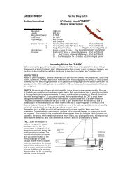
<strong>Pober</strong> <strong>Pixie</strong><br />
• Centre section - (DET. 9): slide the 5/4 mm Ø brass tubes into the prepared holes (wing joiner rod<br />
sleeves - see drawing).<br />
• Slide the 4 mm Ø steel rods into the pre-drilled holes in the root ribs and assemble the outboard<br />
wing panels with the centre section on a flat workbench.<br />
• The centre section ribs are angled at the correct dihedral (1°) - pack up both wingtips by about 15<br />
mm so that the ribs meet accurately.<br />
• When the wing panels are prepared as described, remove the outboard panels and centre<br />
section and remove the steel joiner rods and brass tubes. Apply glue to the holes, fit the joiner<br />
rods and brass tubes again, and set up the wings as previously described (correct dihedral!).<br />
Tip: place PVC film under the joiner rods to prevent them becoming glued in place. Apply a little PVC<br />
adhesive tape to the wing root rib (pierce and cut the holes for the steel joiner rods) to prevent the<br />
outboard panels sticking to the centre section. The “loose” ends of the rods which are fitted in the<br />
brass tube should be waxed to prevent them becoming stuck permanently.<br />
Use epoxy resin for these joints.<br />
• Prepare the servo plate #2 for the left and right wings to suit the servos you intend to fit. This<br />
assembly is shown in Section B-B.<br />
• The suggested installation method provides easy access to the servos for installation and<br />
subsequent removal even after the wings have been covered.<br />
• Cut the machined ailerons free from the wings, and sand the cut edges smooth.<br />
• Cut a slot in each aileron for the GRP horns exactly in line with the aileron servo pushrod (see<br />
Section B-B for the location and orientation of the horns).<br />
• The horns should be epoxied in their slots, but not until the wing has been film-covered.<br />
• Epoxy the hooks in the root ribs for the wing joiner spring, as shown in the drawing.<br />
Wing struts<br />
The struts are fully functional and are essential; it is therefore important to adhere strictly to the<br />
building <strong>instructions</strong>. Note that the front and rear struts are different lengths.<br />
• Glue the pre-shaped balsa block (strut support reinforcement) to the rear spar as shown in the<br />
drawing.<br />
• The support blocks which are fitted to the front of the mainspar are supplied factory-prepared.<br />
• The GRP strut supports should be epoxied in the prepared slots, but only after the wings have<br />
been film-covered.<br />
• The profiled wing struts are supplied pre-cut to the correct length.<br />
• Drill 2.2 mm Ø holes to a depth of about 25 mm in both ends of the struts, and epoxy an M2<br />
threaded rod in each as shown in the drawing (DET. 12). The overall length of this assembly<br />
should be 455 mm for the front struts, and 465 mm for the rear ones. Secure the steel M2 clevis<br />
with a locknut. This construction provides excellent strength and makes it simple to assemble and<br />
disassemble the model.<br />
• Take care to make the front and rear struts the correct length - they are not the same!<br />
• We recommend that you cover the struts with film before painting them.<br />
Wing centre section<br />
All you have to do to complete the centre section is to glue in the brass tubes for fixing it to the<br />
cabane, which is already in place.<br />
• Position the centre section carefully on the cabane (see drawing), locating the pre-drilled holes in<br />
the centre of the glued-in strip, and mark the position of the front hole on the cabane using a soft<br />
pencil or pin, working through the pre-cut holes.<br />
• Drill the front hole 3 mm Ø.<br />
• Glue the M3 captive nut in the prepared hole (DET. 13).<br />
Tip: the wing centre section must be positioned accurately on the cabane: attach the outboard wing<br />
panels to the centre section and place the assembly on the cabane. Pack up the wingtips, set the<br />
fuselage horizontal and check using the thread method that the distance between fin and wingtips is<br />
the same on both sides.<br />
• Working from the underside, glue the M3 captive nut in the front hole of the cabane, together with<br />
the brass spacer tube; the sleeve must end flush with the bottom surface of the film covering<br />
(DET. 13).<br />
<strong>Pober</strong> <strong>Pixie</strong> building <strong>instructions</strong><br />
6