Download Manual for Aero-naut Buecker Jungmeister 133
Download Manual for Aero-naut Buecker Jungmeister 133
Download Manual for Aero-naut Buecker Jungmeister 133
- No tags were found...

You also want an ePaper? Increase the reach of your titles
YUMPU automatically turns print PDFs into web optimized ePapers that Google loves.
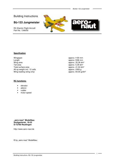
Bücker <strong>133</strong> <strong>Jungmeister</strong>Building InstructionsBü-<strong>133</strong> <strong>Jungmeister</strong>RC-Electric Flight AircraftPart No. 1348/00SpecificationWingspanLengthWing areaTail areaTotal surface areaAll-up weight incl. 12 cellsWing loading (wing only)approx.1100 mmapprox.1008 mmapprox. 35,36 dm²approx. 5,39 dm²approx. 41,04 dm²approx. 2300 gapprox. 64,55 g/dm²RC functions:• elevator• aileron• rudder• motor speed„aero-<strong>naut</strong>“ ModellbauStuttgarterstr. 18-22D-72766 Reutlingenhttp://www.aero-<strong>naut</strong>.de© by „aero-<strong>naut</strong>“ ModellbauBuilding Instructions Bü-<strong>133</strong> <strong>Jungmeister</strong>1
Bücker <strong>133</strong> <strong>Jungmeister</strong>The most appropriate power plant <strong>for</strong> our Bücker <strong>133</strong> is the actro 12-5, which provides plenty of powerwhilst allowing the model to fly at a slow scale speed. The full-size Bücker <strong>133</strong> is not a high-speedaircraft, so the model is best suited to a geared motor and 10 - 12 standard-size cells (1700 - 2400mAh capacity).An alternative and extremely useful power’ plant is the Speed 600 Race 8.4 V with 3.54:1 gearbox and12 cells. This motor has to be converted to left-hand rotation <strong>for</strong> use with our gearbox, but this is noproblem with a little skill and the right tools.The first step is to release the backplate, which is held on the motor can by two pressed-in lugs. Cutthrough the motor jacket on either side of the lugs using a small, high-speed grinder (e.g. Proxxon)and a miniature disc cutter, then make a third cut across the lugs to remove them. This action releasesthe backplate, and should be rotated to the right (opposite to the new direction of rotation) by about 12- 13 mm. This dimension is measured at the periphery of the motor can.To fix the backplate in its new position, cut new slits in the motor jacket using the same disc cutter, inline with the recesses in the backplate, and about 2 - 3 mm apart. This creates two new lugs whichcan be pressed carefully into the recesses using a vice.We recommend fitting a soft steel flux ring to this motor; ensure that the gap in the ring is locatedcentrally over one of the magnets! The flux ring improves the motor’s efficiency and reduces currentdrain.You will require an 13/11 mm Ø aluminium spacer ring to mate the motor to the gearbox. If you don’twish to convert the motor in this way, you will need to obtain a different type of gearbox which doesnot reverse the direction of rotation of the motor. The Reisenauer Micro-Edition 3.5:1 planetarygearbox is an excellent choice; be sure to order a mounting flange with an 11 mm Ø bore.Another very good choice would probably be one of the Ultra 920 motor series, mated with a gearboxsuch as the Kruse Intro Gear 400 (internal-tooth gear) or Syncrogear 800 (toothed belt reducer). Thiscombination should provide plenty of power even with only 10 cells.Nowadays the cream of the crop is the brushless motor. These power plants offer tremendouspotential per<strong>for</strong>mance, very high efficiency and very low weight. Companies such as Kruse, Kontronikand Reisenauer will be glad to advise you by telephone, and help with in<strong>for</strong>mation on drive systemcomponents.12-cell power system:Speed 600 Race 8.4 V (+ flux ring Order No. 7124/27)Gearbox, consisting of:Motor mount “M” with gearbox housing Order No. 7120/95 + 7120/99Aluminium spacer ring, 11 Ø x 13 Ø x 3.5 mm3.54:1 gear set Order No. 7120/74Front ballrace, 1 off Order No. 7821/51Rear ballrace, 1 off Order No. 7822/5010.5 x 7” E-propeller Order No. 7228/56 or 7229/56Caution: the motor bulkhead has no sidethrust or downthrust, and the motor mount must be installedwith 3º downthrust and 3º sidethrust. This is achieved by fitting 2.3 mm packing (three washers (87))under the top and lower left mounting points (all directions as seen from the tail, looking <strong>for</strong>ward).actro 12-5 Order No. 7002/05actronic 40-18 Order No. 7002/5212 x 7” propelleractro GRP bulkhead with stand-off pillars Order No. 7002/88Caution: the motor bulkhead has no sidethrust or downthrust, and the actro motor must be installedwith 3º downthrust and 3º sidethrust. This is achieved by fitting 2.3 mm packing (three washers (87))under the top left stand-off pillar (all directions as seen from the tail, looking <strong>for</strong>ward).10-cell power system:actro 12-4 Order No. 7002/04actronic 40-18 Order No. 7002/5210.5 x 7” propeller Order No. 7229/56actro GRP bulkhead with stand-off pillars Order No. 7002/88Building Instructions Bü-<strong>133</strong> <strong>Jungmeister</strong>2
Bücker <strong>133</strong> <strong>Jungmeister</strong>Caution: the motor bulkhead has no sidethrust or downthrust, and the actro motor must be installedwith 3º downthrust and 3º sidethrust. This is achieved by fitting 2.3 mm packing (three washers (87))under the top left stand-off pillar (all directions as seen from the tail, looking <strong>for</strong>ward).Kontronik SUN 480.33 with 4.2:1 gearbox11 x 6“ propellerKontronik SUN 520-27 with 3.71:1 gearbox12 x 8” propellerIt is also possible to install a power system based on a glowplug motor; details are left to the builder’sdiscretion. A two-stroke of around 4.5 to 5 cc or a four-stroke of 5 to 6.5 cc would be a good choice.The ideal power plant would be our Saito FA 30, Order No. 7100/01 or 7100/02 with a 10 x 6”propeller, Order No. 7244/64 or 7241/60.Caution: the motor bulkhead has no sidethrust or downthrust, and the motor must be installed with 3ºdownthrust and 3º sidethrust.Preparations <strong>for</strong> construction:The building instructions include a reduced-scale drawing of the die-cut plywood sheets. Use thisdrawing to identify the components, and write the part numbers on them using a soft pencil. It is bestto use a balsa knife to remove the components from the sheets. Trim all parts be<strong>for</strong>e fitting; many areslightly oversize to allow <strong>for</strong> this. You can deviate from the sequence of operations described in thebuilding instructions if you wish, but do consider carefully, otherwise you might encounter problemslater. During the construction process use the building instructions, parts list, motor and gearbox,servos, receiver and your selected battery as aids and reference points.Adhesives: the wooden sub-assemblies are supplied factory-built and almost finished, but pleasenote the following points regarding the use of laminating resin as an adhesive, which we stronglyrecommend. This material is fairly slow-setting, but it penetrates into the smallest gaps, and producesreally strong joints. Remember that glued joints involving GRP parts will only be really sound if thesurface is roughened be<strong>for</strong>ehand by rubbing with abrasive paper. You will need to add a thixotropicfiller to the resin <strong>for</strong> some joints, as this allows you to apply it in exactly the right place, without itrunning away from the joint! Laminating resin and fillers are available in any good model shop.The kit is highly pre-fabricated, but some building experience and manual skill are required tocomplete the model successfully.Please note:Revised Centre of Gravity: 43-51 mm aft of the root leading edge of the bottom wing.Centre of Gravity 43-51 mmBuilding Instructions Bü-<strong>133</strong> <strong>Jungmeister</strong>3
Bücker <strong>133</strong> <strong>Jungmeister</strong>Wings and tail surfaces:The wing panels are supplied with their basic structure complete. Each wing consists of a left and rightpanel and a centre section. The joints are arranged in such a way that the root ribs of all the outboardpanels are set at the same angle, which means that the top and bottom outer wing panels areinterchangeable. The ribs feature pre-cut openings <strong>for</strong> the servo leads.The ailerons have to be separated from all four outboard wing panels, as shown on the plan. Werecommend the use of a fine fretsaw to cut the ailerons out. Shorten the ailerons by about 2 mm atboth ends to allow <strong>for</strong> the thickness of the half-ribs (42). The end-gap between ailerons and wingsshould be about 1 mm wide.Trim the wingtip components to fit neatly, fix them in place with a little cyano, and apply Ponal-Expressalong all the joints to rein<strong>for</strong>ce them. When the glue has set hard, sand the wingtips smooth and flushusing a sanding block. Cut the servo mounting plates from the 1 mm plywood (84) supplied, and installthem as shown in the wing plan view and Section B-B. Glue 2 mm balsa sheet to the plates to stiffenthem, and line the servo compartment with the same material. The plan view of the wing shows asuggested method of retaining the servos: cut two blocks from hardwood strip and glue them to themounting plate; the servo is held in place by a strip of sheet aluminium, plywood or similar materialabout 8 mm wide, fixed with two screws.Section B-B shows the servo / aileron linkage (bottom wing!). Drill a 3 mm Ø hole in the ailerons toaccept the horns (72), and run a few drops of thin cyano into them to harden the material. Run the 3mm Ø drill through the hole again when the glue has cured. The horns are fitted permanently at a laterstage, when the model has been covered.The top ailerons are actuated by means of the link pushrods (58), as shown in Section A-A. At thisstage all you have to do is cut the slots in the ailerons to take the glue-fitting GRP horns (56). Thehorns (56) should be tacked in the slots with a drop of thin cyano, then the joints rein<strong>for</strong>ced withlaminating resin. Sand off the excess horn material on the top surface when the glue has cured.Drill 3 mm Ø holes in the wings <strong>for</strong> the interplane struts as shown in the wing plan view. Push shortpieces of plastic sleeve (30) through the bottom wing and glue them in place with thin cyano. SeeSection A-A here, which shows the wing strut guides. The threaded sleeves (30.1) are fitted later.The next step is to join the wing panels, but be<strong>for</strong>e you do this the servo extension leads must befitted. Be sure to use servo leads with integral suppressors, or twisted cables!Cut two 12 mm Ø servo lead exit holes in the top sheeting of the bottom wing centre section. Tip: cutpieces of suitable cable duct material (e.g. drinking straws) about 200 mm long, and fit them in thecentre section from both sides, to <strong>for</strong>m a guide <strong>for</strong> the leads through the sheeted portion of the wing(including the outboard wing panels). Leave part of the cable ducts projecting; they are pushed intothe outboard wing panels when the wings are joined. The servo leads can then be pulled through fromthe centre with the connectors already soldered on, and the servo leads can easily be soldered to theextension leads.Join the wing panels using thickened laminating resin, and be sure to carry out this important stageover a perfectly flat building board! Apply strips of adhesive tape either side of all joints be<strong>for</strong>e applyingthe adhesive. The tape can be removed when the joint has cured, keeping the wood surfacesunsullied, and making any cleaning up much easier. Protect the building board with plastic film overthe joint area be<strong>for</strong>e gluing the parts together. Prepare two strips of wood 10 mm and 24 mm wide,and around 100 - 120 mm long. These set the correct dihedral.Apply an even coating of thickened resin to the mating surfaces, slip the cable duct into the outboardpanel, and press the parts together. Fit the appropriate packing pieces under the wingtips, and pinthem down. Remove excess resin, and carefully fix the outboard panels to the building board and thecentre section to ensure that the glued joints are 100% sound. Clean up the joints carefully withthinners on a piece of kitchen paper.When the resin has cured completely, sand both wings smooth overall, taking particular care over thejoint areas. Cut the curved opening in the top wing with the help of the template S2, which is shown onthe plan, and round off the trailing edge as shown in Section C-C. Cut strips of tissue about 15-20 mmwide and glue them over all four wing joints using laminating resin as adhesive. Sand the tissue lightlywhen the glue is hard.FuselageCarefully remove any rough edges from the GRP fuselage (1) and motor cowl (2), and sand all jointareas thoroughly with abrasive paper to provide a “key” <strong>for</strong> the adhesive, i.e. at all points where theBuilding Instructions Bü-<strong>133</strong> <strong>Jungmeister</strong>4
Bücker <strong>133</strong> <strong>Jungmeister</strong>die-cut parts are to be installed. Remove rough edges from the fin and tailplane slots, the bowdencable exit slots and the cockpit opening using a high-speed diamond cutter. Rub down the wholefuselage and cowl using 400-grit wet-and-dry paper, used wet, to ensure that the final painted finishadheres really well.Glue together the tailskid mount (21), the motor bulkhead (4+5), the tail post (3) and the wing retainerplates (19) in pairs, using laminating resin to produce really strong joints. When the resin has cured,glue the tailskid mount (21) in the fuselage using thickened laminating resin. When the glue has sethard, apply thickened laminating resin all round the tailskid mount (21) to rein<strong>for</strong>ce the joint. Mix upsome extremely thick resin and apply it between the tailskid mount (21) and the fuselage sides to <strong>for</strong>mfillets. When the resin has cured completely, drill a 2 mm Ø hole through the mount at right-angles tothe fuselage bottom. Assemble the servo mounts, fit the rails (46), and install the servos in the mounts.Drill out the servo output arms to 2 mm Ø to accept the pushrod connectors (74), and install theconnectors. You can now drill the 2 mm Ø hole in parts (44) to accept the bowden cables (28); don’tdo this earlier, as the holes must line up with the pushrod holes in the connectors (74).You will find marked points on the half-<strong>for</strong>mers (26) and (27); these are guide-holes <strong>for</strong> the bowdencables and should be drilled 2 mm Ø. Mark the position of parts (26) and (27) on the fuselage and tackthem in place using cyano, then rein<strong>for</strong>ce the joints with thickened resin. It is best to install the bowdencables (28) and (30) through the fuselage from the rear, threading them through parts (26), (27) and(44). Tack the bowden cables to the fuselage using thin cyano where they project at the tail end, thenapply a fillet of thickened resin on the inside of the fuselage. Tack the receiver aerial tube (30) to thefuselage side using thin cyano, then apply resin at several points to hold it in place. When the resinhas cured, carefully slice off the excess bowden cable outers using a sharp chisel, leaving them flushwith the surface. Glue the already joined wing retainer plates (19) in the fuselage as shown on theplan; use thickened resin and take care to produce strong joints at this important location.Mark the position of the holes <strong>for</strong> the wing dowels (63) on the fuselage as shown on the plan, and drillthem 3 mm Ø. File out the holes to 4 mm Ø, and check that the dowels are an easy, sliding fit, withoutbeing sloppy.Place the bottom wing on the fuselage, align it carefully and tape it in position, so that you can markthe position of the dowels (63) on the wing leading edge working through the holes you have just cut.Cut slots about 8-10 mm wide in the top wing skin at the dowel positions; the correct length is shownon the plan. Cut semi-circular channels in the top of the channeled rail (undercarriage support rail) toaccept the wing dowels - see plan. With the fuselage seated on the wing, check that the dowels arecorrectly located. If everything looks right, apply a little thickened resin to the recesses in thechanneled rail, press the dowels into place from above, position the wing carefully on the fuselage andsecure it again. When the resin has set hard, remove the wing, apply more resin round the dowels intheir seating, and fill the slots with scrap balsa.Fit the wing on the fuselage, align it as accurately as possible, and mark the position of the two holesin the bottom wing centre section (49) on the fuselage, ideally using a 5 mm Ø drill bit. Drill the holesat the marked points using a 4 mm Ø drill, then cut the thread <strong>for</strong> the wing retainer screws using an M5tap. Run a little thin cyano into the tapped holes, allow it to cure completely, then run the tap throughthe holes again to clean up the threads.Drill 4 mm Ø holes in the cabane plates (6), and glue them in the fuselage using thickened resin; theholes in parts (6) must line up with the pilot-drilled holes in the fuselage. When the resin has set hard,file out the holes neatly so that the brass sleeves (7) can be slid easily into place, without requiring<strong>for</strong>ce. Cut two pieces 122 mm long from the brass tube (7). The next step is to roughen the surface ofthe tubes prior to gluing: place the tube on a hard surface, press a sharp, flat file on top and roll it toand fro. De-grease the tubes, tack them in place with a little thin cyano, then apply thickened resin onthe inside of the joints on both sides.Assemble the flight pack cradle and glue the joints with thin cyano be<strong>for</strong>e rein<strong>for</strong>cing them withlaminating resin. Check that the lugs of the battery cradle engage neatly in the slots in the motorbulkhead.The instrument panel (22) should be fixed to the fuselage using Velcro (hook-and-loop) tape so that itcan be removed easily <strong>for</strong> battery replacement.Sand the periphery of the motor bulkhead to match the taper of the fuselage, and drill the holesrequired <strong>for</strong> your selected motor mount. Place the bulkhead in the fuselage, position it as accurately aspossible, and tack it in place with thin cyano. Apply laminating resin all round the periphery to <strong>for</strong>m areally strong joint. We recommend that you rein<strong>for</strong>ce the joint all round with a strip of glass tape about15 - 20 mm wide.Building Instructions Bü-<strong>133</strong> <strong>Jungmeister</strong>5
Bücker <strong>133</strong> <strong>Jungmeister</strong>Adjusting the top wing:The kit includes two die-cut jigs S1. Carefully cut out these parts and the triangular gussets using abalsa knife. It is important that the jigs should be flat; if they are not, glue scrap pieces of spruce stripto them to stiffen them.Position the jigs S1 on the building board as shown on the plan. We recommend that you glue them inplace temporarily with cyano, using the gussets to set them exactly at right-angles to the buildingboard. Glue a scrap piece of 5 mm thick balsa or similar material centrally between them as shown -this <strong>for</strong>ms the support <strong>for</strong> the bottom wing.Place the model between the jigs, with the wing fitted inside them, and the wing trailing edges restingagainst the jigs S1. Pin the parts together. Check that the bottom wing rests squarely on the 5 mmsupport under the fuselage!Sand the joint areas of the cabane struts (9), (10) and (11) with abrasive paper prior to soldering. Takecare! Parts (9) and (10) are supplied in the kit as handed pairs, i.e. one left, one right: see fuselageplan view. This means that you must select the correct part (11) <strong>for</strong> each side of the cabane assembly,as the angled ends of parts (11) are not identical. Locate the end with the tighter bend, and bind ittightly to the rear cabane strut (10) using soft wire. Solder the joints carefully, noting that part (11)must be at right-angles to the angled bottom end of part (10) when viewed from above or below.Cut down the wing retainer screws (61) to a length of about 10 mm, and screw the cabane struts (9)and (10+11) to the right wing panel as shown on the plan (note position of screw loops). Now fit parts(9) and (10+11) in the brass tubes (7) which are already installed in the fuselage, align the top wingwith the jigs S1, and pin it in place with the trailing edge resting against the jigs. The left-hand parts (9)and (10+11) can now be fitted. Adjust the cabane struts (11) if necessary, bind the joints tightly withsoft wire, and solder them securely. The top wing should now be set at an angle of incidence of -0.5ºto -1.0º relative to the building board (= underside of bottom wing). If corrections are required at a laterstage, this can be done by placing packing washers on the cabane screw loops. Be<strong>for</strong>e gluing thecabane assembly permanently to the fuselage, attach the strut fairings (13) to the wire parts, cover thesurfaces with tissue and apply sanding sealer. Remove the top wing, file notches in those parts of thecabane which project into the fuselage, then roughen and de-grease the parts, including the inside ofthe brass tubes. Glue the cabane to parts (7) using laminating resin; fit the top wing, fix the model inthe jigs S1 as be<strong>for</strong>e, and leave it there until the resin has cured.The wing struts (54) consist of steel rods with an M2 thread at both ends. The length of the straightsection, i.e. between the top and bottom angles, is best found by taking direct measurements while themodel is still set up in the jigs S1. Fit two washers (55) on each wire strut and insert the struts in thewings. Position the washers resting against the wing surface and solder them to the wires, afterprotecting the wood with scrap paper or similar. Secure the bottom end of the struts with the washers(55) and M2 self-locking nuts (86). We recommend that you glue at least one half of the strut fairings(13) to the struts with cyano at this point.Mark the struts be<strong>for</strong>e removing them, to avoid mixing themup later.Undo and remove the top wing from the cabane, roughen the outside of the threaded sleeves (30.1),and screw them on the top end of the struts as far as the soldered-on washers. Run a little laminatingresin into the 3 mm Ø holes in the top wing and fit the model in the jigs S1 again. Place the top wingon the threaded sleeves, and screw the wing to the cabane assembly.Temporarily attach the ailerons to the wings. Assemble the link pushrods <strong>for</strong> the top ailerons usingparts (57-60), as shown in Section A-A.The top wing is removed as follows: first undo the four M2 nuts; of course, the top end of the struts isnow screwed to the wing. Unscrew the struts, glue the second half of the fairings to them, and sandthem to the correct profile. We recommend that you tissue-cover the strut fairings and seal thesurfaces.Place the undercarriage legs (31) and (32) in the fuselage channels as shown on the plan, and fit thestraps (17) to secure them. Attach the undercarriage cross-piece (15) to the legs, bind the joints tightlywith soft wire, and solder the joints. It is important that the wheels should have around 2º toe-in perside, as this improves the straight-running characteristics of the model considerably. Place thefuselage on the building board without the wheels, and hold a straight edge (steel rod or similar)against the front of the wheel axles. The outside end of the axles should touch the straight edge, and<strong>for</strong>m a curved gap towards the fuselage centreline. If necessary, adjust the angle of the axles until thisis the case. Remove the undercarriage and solder the top brace (14) to the assembly as shown on theplan. Carefully trim the undercarriage fairings (38) to fit and glue them to the legs using Stabilit-Express. Any gaps can be made good using polyester filler paste. The wheels (33) are designed <strong>for</strong> 4mm Ø axles, so <strong>for</strong> this model a 4/3 mm Ø brass reducer sleeve (34) must be pushed into each wheel.Building Instructions Bü-<strong>133</strong> <strong>Jungmeister</strong>6
Bücker <strong>133</strong> <strong>Jungmeister</strong>Check that the wheels are absolutely free to spin, with very little axial play. A drop of thin oil willlubricate the wheels effectively.Roughen up the top section of the tailskid (66), file notches in it, and de-grease the surface. Solder thetop washer (55) in place be<strong>for</strong>e gluing the unit in the hole in the fuselage (using laminating resin).Open up the hole in the tailwheel (64) to 3 mm Ø, and press the 3/2 mm Ø brass sleeve (65) into it.Secure the wheel by soldering two washers (55) to the axle.The basic structure of the tail panels is completed at the factory. All you need to do is round off the tipsand sand the surfaces smooth. Drill 3 mm Ø holes <strong>for</strong> the horns (72) in the elevators and rudder, andapply thin cyano to the holes to strengthen the material.With the bottom wing attached to the fuselage, slide the tailplane into its slot. Check alignment with thewing, and measure the tail incidence and longitudinal dihedral. When you are confident that everythingis positioned correctly, glue the tailplane to the fuselage using laminating resin. Glue the fuselage tailpost (3) in place, followed by the fin.The motor cowl is attached to the fuselage as shown on the plan. Tip: tack a piece of plywood to themotor bulkhead on the motor cowl axis and mark the centrepoint. From this starting point it is easy tomeasure off the correct distance to the end of the three cowl support rails (8); this ensures that thecowl is truly central.The kit includes a number of optional scale fittings, and the plan clearly shows how these parts areinstalled. Just one tip here: the wire bars (36) which support the mudguards should be soldered intothe collets (37). Drill the collets to accept the wires using a 1.2 mm Ø bit.Preparing and covering the flying surfaces:Be<strong>for</strong>e covering we recommend that you give all the wooden parts a coat or two of thinned sandingsealer. When the sealer has set hard, rub down to a completely smooth surface using 400-gritabrasive paper, and blow away the sanding dust with compressed air. You have already sanded theGRP parts and ABS plastic mouldings, and they should now be de-greased using a detergent solution,and then allowed to dry really thoroughly be<strong>for</strong>e painting.The lightest covering material is probably iron-on film. However, as some parts of the model have tobe painted, you should ensure that the colours of the film and paint are a good match. We recommendOracover film and Orapaint colour paint, both in the colour CUB YELLOW. The paint adheres welleven on the film, i.e. you can safely spray the red areas onto the yellow Oracover. The dummy engine,exhaust pipe and instrument panel are best painted using enamels intended <strong>for</strong> plastic kits (e.g.Humbrol, Revell etc.).When the final finish has been applied, assemble the model completely, ready to fly, and balance it byadjusting the position of the flight battery (stated CG position refers to bottom wing). Fix the batterysecurely in its final position. You may find it necessary to use two packs, one above the other, in orderto balance the model correctly.Centre of Gravity 43-51Re-check the longitudinal dihedral, program the correct control surface travels and check that theundercarriage produces a straight ground-roll (check toe-in if not).As the model is relatively small and the power relatively high, the very large propeller produces quite amarked tendency to swing left on the take-off run. The best way of avoiding this problem is to increasemotor power gradually, initially accelerating with the tailwheel on the ground (i.e. with up-elevator heldin). Apply right rudder to maintain the correct heading, and when adequate speed has built up, returnthe elevator to neutral and continue to accelerate until the model lifts off by itself. The Bücker’shandling is extremely good-natured in the air. It is also capable of aerobatic manoeuvres, but its scopeBuilding Instructions Bü-<strong>133</strong> <strong>Jungmeister</strong>7
Bücker <strong>133</strong> <strong>Jungmeister</strong>depends on the power available.Initiate the landing approach with the motor still running, and flare out gently close to the ground; chopthe throttle, and it will settle neatly by itself.We hope you have many hours of pleasure flying your new model.Happy landings!“aero-<strong>naut</strong>” ModellbauBü-<strong>133</strong> <strong>Jungmeister</strong> parts listPart Description No. Material Dimensions in mmNo.off1 Fuselage 1 GRP Ready made2 Motor cowl 1 GRP Ready made3 Fuselage tail post 2 Plywood 3 mm, die-cut4 Motor bulkhead 1 Plywood 3 mm, die-cut5 Motor bulkhead 1 Plywood 3 mm, die-cut6 Cabane plate 4 Plywood 3 mm, die-cut7 Sleeve Brass 2.5 / 4 Ø8 Motor cowl rail Lime 8 x 8, as plan9 Cabane strut 2 Steel Ready made10 Cabane strut 2 Steel Ready made11 Cabane strut brace 2 Steel Ready made12 Triangular strip Balsa 5 x 25, as plan13 Profiled fairing Balsa Profiled /strip14 Undercarriage brace 1 Plated steel Ready made15 Undercarriage cross-piece 1 Plated steel Ready made16 Rubber band, undercarriage 1 Rubber Ready made17 Undercarriage retainer strap 4 Plastic Ready made18 Self-tapping screw 12 Steel 2.2 Ø x 9.519 Wing mount plate 4 Plywood 3, die-cut20 Wire “star”, motor Plated steel 1.2 Ø, as plan21 Tailwheel unit support 2 Plywood 3, die-cut22 Instrument panel 1 Plastic Ready made23 Pilot’s seat 1 Plastic Ready made24 Headrest 1 Plastic Ready made25 Velcro tape Plastic Ready made26 Half-<strong>for</strong>mer 1 Plywood 3, die-cut27 Half-<strong>for</strong>mer 1 Plywood 3, die-cut28 Bowden cable inner sleeve 3 Plastic 1 / 2 Ø, as plan29 Steel rod 3 Steel 0.8 Ø, as plan30 Bowden cable outer sleeve 1 Plastic 2 / 3 Ø, as plan30.1 Threaded sleeve 4 Metal 3 / 8 Ø, M231 Main undercarriage unit 1 Steel Ready made32 Rear undercarriage unit 1 Steel Ready made33 Balloon wheel 2 Plastic 72 Ø, ready made34 Wheel bush Brass 3 / 4 Ø35 Mudguard 2 Plastic Ready made36 Mudguard support bar Plated steel 1.2 Ø, as plan37 Collet 4 Brass Ready made38 Undercarriage fairing 2+2 Plastic Ready made39 Dummy engine 1 Plastic Ready made40 Exhaust collector ring 1 Plastic Ready made41 Exhaust 1+1 Plastic Ready made42 Half-rib 8 Plywood 3, die-cut43 Servo mount, side 2 Plywood 3, die-cut44 Servo mount, side 2 Plywood 3, die-cut45 Servo mount 2 Plywood 3, die-cutBuilding Instructions Bü-<strong>133</strong> <strong>Jungmeister</strong>8
Bücker <strong>133</strong> <strong>Jungmeister</strong>46 Servo mount rail Lime 6 x 6, as plan47 Top wing centre section 1 Balsa Ready made48 Top wing outboard panel 1+1 Balsa Ready made49 Bottom wing centre section 1 Balsa Ready made50 Bottom wing outboard panel 1+1 Balsa Ready made51 Wingtip 4 Plywood 3, die-cut52 Wingtip gusset 4 Plywood 3, die-cut53 Wingtip gusset 4 Plywood 3, die-cut54 Wing strut (threaded rod) 4 Plated steel 2 mm Ø, M2, as plan55 Washer 16 Brass 2 Ø, as plan56 Horn 4 GRP Ready made57 Clevis 4 Steel Ready made58 Threaded rod 2 Plated steel M2 / 2 Ø, as plan59 Threaded coupler 2 Steel Ready made60 Nut 4 Brass M2, ready made61 Wing retainer screw 4 Plastic M4, ready made62 Wing retainer screw 2 Plastic M5, ready made63 Wing locating dowel 1 Beech 4 Ø, as plan64 Tailwheel 1 Plastic 35 Ø, ready made65 Wheel bush 1 Brass 2 / 3 Ø, as plan66 Tailwheel unit 1 Steel Ready made67 Wingtip gusset 4 Plywood 3, die-cut68 Fin 1 Balsa Ready made69 Rudder 1 Balsa Ready made70 Tailplane 1 Balsa Ready made71 Elevator 1+1 Balsa Ready made72 Horn 5 Plated brass Ready made73 Horn screw 5 Brass M2 x 18, ready made74 Servo connector 2 Steel 4.5 / 2 Ø x 10, ready made75 Servo connector 2 Steel 6 / 2 Ø x 10, ready made76 Pilot’s seat base 1 Plywood 3, die-cut77 Washer 4 Brass 2.5 Ø, ready made78 Windscreen 1 Plastic Ready made79 Battery cradle side 2 Plywood 3, die-cut80 Battery cradle bulkhead 1 Plywood 3, die-cut81 Battery cradle cross-piece 1 Plywood 3, die-cut82 Battery cradle cross-piece 1 Plywood 3, die-cut83 Battery cradle cross-piece 1 Plywood 3, die-cut84 Wing servo plate Plywood 1, as drawing85 Wing plate Balsa 2, as drawing86 Self-locking nut 4 Metal M287 Washer, motor 6 Brass 3 ØBuilding Instructions Bü-<strong>133</strong> <strong>Jungmeister</strong>9
Bücker <strong>133</strong> <strong>Jungmeister</strong>Building Instructions Bü-<strong>133</strong> <strong>Jungmeister</strong>10
Bücker <strong>133</strong> <strong>Jungmeister</strong>Text from the plan:1 Glue the star, part 20, to the motor, part 39,using STABILIT-Express. Glue the motor tothe cowl, part 2, using thickened resin2 Wing incidence relative to tailplane +1º3 Spinner, Order No.4 Glue the exhaust, part 41, in the opening inthe cowl, part 2, using STABILIT-Express5 Wing incidence relative to tailplane +1.5º6 Suggested installation of ACTRO 12-5 motor,Order No. 7002/057 Rein<strong>for</strong>ce with woven glass tape8 Order No. 7002/88: GRP motor bulkhead andstand-off pillarsThree 0.8 mm thick washers <strong>for</strong> sidethrust anddownthrust; fit under this pillar only.9 Glue undercarriage leg fairings, parts 38L +38R, to completed undercarriage assemblyusing STABILIT-Express10 Solder part 36 into collet - see buildinginstructions11 Glue mudguard 35 to part 36 using STABILIT-Express12 Bind joint tightly with soft wire, solder jointcarefully13 Applying the hinge tape14 Hinge tape (short pieces)15 Hinge tape (full-length)16 Jig S117 Adjusting the top wing using the jigs S118 We reserve the right to modify any feature inorder to improve our products19 Top wing - dihedral20 Bottom wing - dihedral21 Plan view of bottom wing22 View B23 Position of jig S1 when adjusting the top wing24 Removable seat (23) <strong>for</strong> access to battery25 Fix receiver to fuselage side with Velcro(hook-and-loop) tape26 Bind tightly with soft wire, solder together27 Glue profiled cabane fairing strips, part 13, tocompleted cabane assembly using STABILIT-Express28 Black fuel tubing, 3 ØBlack fuel tubing, 2 Ø, not included29 Velcro (hook-and-loop) tape30 Receiver aerial guide tube31 Edge of decal32 Section B-B33 Shorten part 7234 Bend the “star”, part 20, to shape and solder thejoints35 Solder braces, parts 14, 15, to main undercarriagelegs, part 31; see building instructions36 Brass main wheel bush, part 3437 Hole <strong>for</strong> receiver aerial sleeve, part 3038 Aileron servo lead39 Relieve top of channeled rail - see buildinginstructions40 Cut slot - see building instructions41 Solder parts 9 and 10 to washers, part 7742 Glue cabane struts, parts 9 and 10, in brasssleeves, part 7, using laminating resin43 Slot (left-hand side) - rudder linkage44 Slots (both sides) - elevator linkage45 Fix sleeves, part 30, with thin cyano46 Fix aileron horn 56 with laminating resin47 Section A-A48 Solder washers, part 55, to interplane struts, part5449 View A50 Installation of elevator servo (right-hand fuselageside)51 Section C-C52 Template S253 Solder washer, part 55, to tailwheel unit, part 6654 Tailwheel - see building instructions55 Flight battery: 10 - 12 cells, 1.7 - 2.0 Ah capacity56 Centre of Gravity (C.G.) 43 - 51 mm57 30 mm - see building instructions58 Glue M3 nuts in place using STABILIT-Express59 Glue remainder of part 54 in the cowl and exhaustusing STABILIT-ExpressBuilding Instructions Bü-<strong>133</strong> <strong>Jungmeister</strong>11