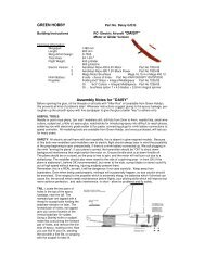
QUIRLI - Green Hobby & Model
QUIRLI - Green Hobby & Model
QUIRLI - Green Hobby & Model

Erfolgreiche ePaper selbst erstellen
Machen Sie aus Ihren PDF Publikationen ein blätterbares Flipbook mit unserer einzigartigen Google optimierten e-Paper Software.
Cut down the output arms supplied with the servos as shown in the photo. Set the<br />
servos to centre, and fit the output arms on the servo shafts at right-angles to the<br />
case sides.<br />
Insert the hinges exactly half-way into the ailerons and secure each with a drop of<br />
cyano.<br />
Allow the glue to set hard, then insert the protruding hinges into the slots in the wings<br />
and apply another drop of cyano to each hinge.<br />
The aileron servos can now be installed in the wings using the retaining screws<br />
supplied with them, as shown in the photo. Drill pilot-holes before fitting the screws.<br />
Run the servo leads out of the openings in the root ribs.<br />
Connect the pre-formed end of the aileron pushrods to the servo output levers.<br />
Position the horns on the ailerons in such a way that the pushrods are at right-angles<br />
to the aileron leading edge. Fix the horns to the ailerons after drilling 1.5 mm Ø pilotholes<br />
for the screws; note that the spreader plates are not used in this instance.<br />
Set the ailerons and servos to centre, and bend the plain end of the pushrods at<br />
right-angles using a pair of stout pliers. Shorten the projecting ends to the point<br />
where they project by about 1 mm when the retaining clips are fitted.<br />
If necessary, minor inaccuracies in bending the aileron pushrods can be corrected<br />
later using your transmitter’s centre offset facility.<br />
The fuselage<br />
Use your fingers to locate the openings in the fuselage for the rudder and elevator<br />
servos and the undercarriage slot, and remove the film over them using a hot<br />
soldering iron, as shown in the photos.<br />
Insert the tailplane and fin in the slots in the tail end of the fuselage, and align them<br />
carefully: the tailplane must project by an equal amount on each side, and must be at<br />
right-angles to the fuselage centreline when viewed from above.<br />
Run a felt-tip pen along the edges of the fuselage at the tailplane and fin to mark the<br />
excess film.<br />
Remove the tail panels and melt the film by running a hot soldering iron just inside<br />
the marked lines; peel away the unwanted film.<br />
GRAUPNER GmbH & Co. KG D-73230 KIRCHHEIM/TECK GERMANY<br />
Änderungen vorbehalten! Keine Haftung für Druckfehler 12/2006<br />
32