Building instructions Fournier RF-4D - Aero-naut
Building instructions Fournier RF-4D - Aero-naut
Building instructions Fournier RF-4D - Aero-naut
Create successful ePaper yourself
Turn your PDF publications into a flip-book with our unique Google optimized e-Paper software.
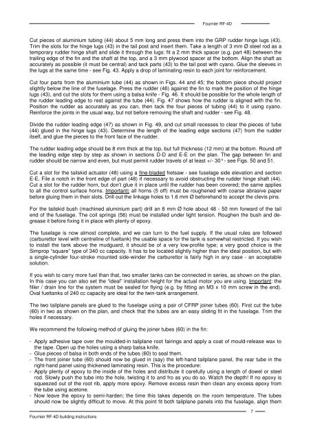
<strong>Fournier</strong> <strong>RF</strong>-<strong>4D</strong>Cut pieces of aluminium tubing (44) about 5 mm long and press them into the GRP rudder hinge lugs (43).Trim the slots for the hinge lugs (43) in the tail post and insert them. Take a length of 3 mm Ø steel rod as atemporary rudder hinge shaft and slide it through the lugs: fit a 2 mm thick spacer (e.g. part 48) between thetrailing edge of the fin and the shaft at the top, and a 3 mm plywood spacer at the bottom. Align the shaft asaccurately as possible (it must be central) and tack parts (43) to the tail post with cyano. Glue the sleeves inthe lugs at the same time - see Fig. 43. Apply a drop of laminating resin to each joint for reinforcement.Cut four parts from the aluminium tube (44) as shown in Figs. 44 and 45; the bottom piece should projectslightly below the line of the fuselage. Press the rudder (46) against the fin to mark the position of the hingelugs (43), and cut the slots for them using a balsa knife - Fig. 46. It should be possible for the whole length ofthe rudder leading edge to rest against the tube (44). Fig. 47 shows how the rudder is aligned with the fin.Position the rudder as accurately as you can, then tack the four pieces of tubing (44) to it using cyano.Reinforce the joints in the usual way, but not before removing the shaft and rudder - see Fig. 48.Divide the rudder leading edge (47) as shown in Fig. 49, and cut small recesses to clear the pieces of tube(44) glued in the hinge lugs (43). Determine the length of the leading edge sections (47) from the rudderitself, and glue the pieces to the front face of the rudder.The rudder leading edge should be 8 mm thick at the top, but full thickness (12 mm) at the bottom. Round offthe leading edge step by step as shown in sections D-D and E-E on the plan. The gap between fin andrudder should be narrow and even, but must permit rudder travels of at least +/- 30° - see Figs. 50 and 51.Cut a slot for the tailskid actuator (48) using a fine-bladed fretsaw - see fuselage side elevation and sectionE-E. File a notch in the front edge of part (48) if necessary to avoid obstructing the rudder hinge shaft (44).Cut a slot for the rudder horn, but don’t glue it in place until the rudder has been covered; the same appliesto all the control surface horns. Important: all horns (5 off) must be roughened with coarse abrasive paperbefore gluing them in their slots. Drill out the linkage holes to 1.6 mm Ø beforehand to accept the clevis pins.For the tailskid bush (machined aluminium part) drill an 8 mm Ø hole about 48 - 50 mm forward of the tailend of the fuselage. The coil springs (56) must be installed under light tension. Roughen the bush and degreaseit before fixing it in place with plenty of epoxy.The fuselage is now almost complete, and we can turn to the fuel supply. If the usual rules are followed(carburettor level with centreline of fueltank) the usable space for the tank is somewhat restricted. If you wishto install the tank above the mudguard, it should be of a very low-profile type; a very good choice is theSimprop “square” type of 340 cc capacity. It has to be located slightly higher than the ideal position, but witha single-cylinder four-stroke mounted side-winder the carburettor is fairly high in any case - an acceptablesolution.If you wish to carry more fuel than that, two smaller tanks can be connected in series, as shown on the plan.In this case you can also set the “ideal” installation height for the actual motor you are using. Important: thefiller / drain line for the system must be sealed for flying (e.g. by fitting an M3 x 10 mm screw in the end).Oval fueltanks of 240 cc capacity are ideal for the twin-tank arrangement.The two tailplane panels are glued to the fuselage using a pair of CFRP joiner tubes (60). First cut the tube(60) in two as shown on the plan, and check that the tubes are an easy sliding fit in the fuselage. Trim theholes if necessary.We recommend the following method of gluing the joiner tubes (60) in the fin:- Apply adhesive tape over the moulded-in tailplane root fairings and apply a coat of mould-release wax tothe tape. Open up the holes using a sharp balsa knife.- Glue pieces of balsa in both ends of the tubes (60) to seal them.- The front joiner tube (60) should now be glued in (say) the left-hand tailplane panel, the rear tube in theright-hand panel using thickened laminating resin. This is the procedure:- Apply plenty of epoxy to the inside of the holes and distribute it carefully using a length of dowel or steelrod. Slowly push the tube into the hole, twisting it to and fro as you do so. Watch the depth! If no epoxy issqueezed out of the root rib, apply more epoxy. Remove excess resin then clean any excess epoxy fromthe tube using acetone.- Now leave the epoxy to semi-harden; the time this takes depends on the room temperature. The tubesshould now be slightly difficult to move. At this point fit both tailplane panels into the fuselage, align them<strong>Fournier</strong> <strong>RF</strong>-<strong>4D</strong> building <strong>instructions</strong>7


