- Page 1 and 2: User’sManualHardware ManualIM 34M
- Page 4 and 5: iiImportant• About This Manual- T
- Page 6 and 7: - Yokogawa Electric assumes no liab
- Page 8 and 9: vi• Configure for CE Marking Conf
- Page 10 and 11: viii• Waste Electrical and Electr
- Page 12 and 13: xCopyrights and Trademarks• Copyr
- Page 14: TOC-2A2.5 I/O Modules .............
- Page 18 and 19: Blank Page
- Page 20 and 21: Blank Page
- Page 22 and 23: A1-2• Slot NumberA slot number id
- Page 24 and 25: A1-4TIP■ Example of increasing th
- Page 26: A1-6A1.2.2Restrictions on CPU Modul
- Page 29 and 30: A1-9A1.2.4Restrictions due to Curre
- Page 31 and 32: A2. Specifications and Configuratio
- Page 33 and 34: A2.2 FA-M3 Controller Configuration
- Page 35 and 36: A2-5• ROM PacksModule Description
- Page 37 and 38: A2-7• Analog I/O and Temperature
- Page 39 and 40: • Counter and Positioning Modules
- Page 41 and 42: For detailed cable specifications,
- Page 43 and 44: A2.3 Power Supply ModulesA2-13(1) F
- Page 45 and 46: A2-15(2) F3PU30-0N/F3PU30-0S Power
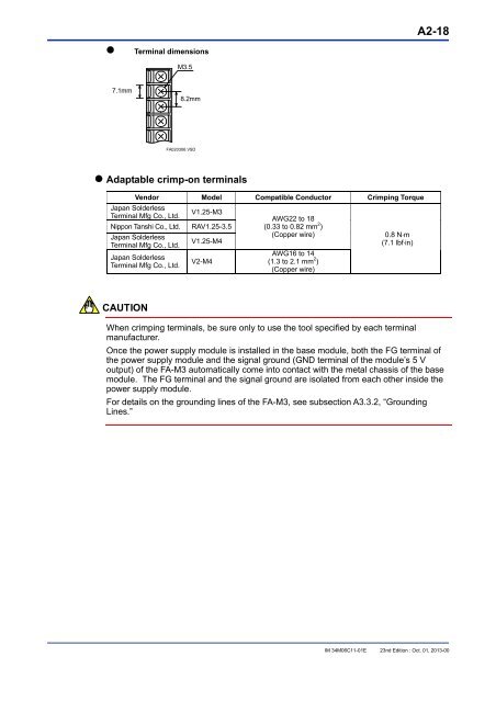
- Page 47: A2-17(3) F3PU16-0N and F3PU26-0N Po
- Page 51 and 52: A2.4 Base ModulesA2-21There are six
- Page 53 and 54: A2-23• Isolation MethodsThe inter
- Page 55 and 56: A2-25• Setting up the Pulse-captu
- Page 57 and 58: A2-27(4) Functional Description- Pu
- Page 59 and 60: A2-29(2) F3XA08-1N/F3XA08-2N AC Inp
- Page 61 and 62: A2-31(3) F3XA16-1N AC Input ModuleI
- Page 63 and 64: A2-33(5) F3XC08-0C No-voltage Conta
- Page 65 and 66: A2-35(7) F3XD16-3F/F3XD16-4F/F3XD16
- Page 67 and 68: A2-37(8) F3XD32-3F/F3XD32-4F/F3XD32
- Page 69 and 70: A2-39(9) F3XD64-3F/F3XD64-4F DC Inp
- Page 71 and 72: A2-41(10) F3XD08-6N DC Input Module
- Page 73 and 74: A2-43(11) F3XD16-3N/F3XD16-4N DC-In
- Page 75 and 76: A2-45(12) F3XD32-3N/F3XD32-4N/F3XD3
- Page 77 and 78: A2-47(13) F3XD64-3N/F3XD64-4N DC In
- Page 79 and 80: A2-49(14) F3XD64-6M DC Input Module
- Page 81 and 82: A2-51(16) F3YA08-2N Triac Output Mo
- Page 83 and 84: A2-53(17) F3YC08-0C/F3YC08-0N Relay
- Page 85 and 86: A2-55• Front View• Internal Cir
- Page 89 and 90: A2-59• Front ViewF3YD08-7A● Int
- Page 91 and 92: A2-61• Front View• Internal Cir
- Page 93 and 94: A2-63• Front View• Internal Cir
- Page 95 and 96: A2-65• Front View• Internal Cir
- Page 97 and 98: A2-67• Front View● Internal Cir
- Page 99 and 100:
A2-69IM 34M06C11-01E 23th Edition :
- Page 101 and 102:
A2-71CAUTIONOperation of the protec
- Page 103 and 104:
A2-73• Front View• Internal Cir
- Page 105 and 106:
A2-75• Front View• Internal Cir
- Page 107 and 108:
A2-77IM 34M06C11-01E 23th Edition :
- Page 109 and 110:
A2-79IM 34M06C11-01E 23th Edition :
- Page 111 and 112:
A2-81• Front View• Internal Cir
- Page 113 and 114:
A2-83*3: If an inductive load, such
- Page 115 and 116:
A2-85IM 34M06C11-01E 23th Edition :
- Page 117 and 118:
A2-87• Output BlockOutput typeIte
- Page 119 and 120:
A2-89IM 34M06C11-01E 23th Edition :
- Page 121 and 122:
A2-91• Output BlockOutput typeIte
- Page 123 and 124:
A2-93IM 34M06C11-01E 23th Edition :
- Page 125 and 126:
A2-95• Maximum Writing Operations
- Page 127 and 128:
A2-97• KM13-1S (USB-serial Conver
- Page 129 and 130:
(3) Cables for Connector Terminal B
- Page 131 and 132:
(5) Fiber-optic CablesA2-101KM61, K
- Page 133 and 134:
A2-103CAUTIONHandle the fiber-optic
- Page 135 and 136:
(7) Monitor Cables (for F3SP66-4S a
- Page 137 and 138:
A2-107A2.8 Terminal Block Unit and
- Page 139 and 140:
A2-109• External DimensionsUnit:
- Page 141 and 142:
A2-111•Operating Environment Spec
- Page 143 and 144:
A2-113(3) TA60-0NThe TA60-0N connec
- Page 145 and 146:
A2.9 Module Current Consumption Tab
- Page 147 and 148:
A2-117I/O moduleModule DescriptionM
- Page 149 and 150:
A2-119A2.10 External Power SupplyUs
- Page 151 and 152:
F3PU01, F3PU10, F3PU16• Power Sup
- Page 153 and 154:
A2-123Unit: mmF3XD32F3XD64-3N, F3XD
- Page 155 and 156:
A3-1A3. Installation and WiringA3.1
- Page 157 and 158:
A3.2 Methods for Mounting the FA-M3
- Page 159 and 160:
A3-5A3.2.3Mounting on and Removing
- Page 161 and 162:
A3-7• Removing the Rail Mount Kit
- Page 163 and 164:
A3-9• Attaching the Module in Int
- Page 165 and 166:
A3-11- In the case of Positioning m
- Page 167 and 168:
A3-13A3.3.2Grounding LinesWhen cons
- Page 169 and 170:
A3-15A3.3.5InterlockingAn interlock
- Page 171 and 172:
• Standard Mode (common to all po
- Page 173 and 174:
A3-19• Immediate Detection Mode(w
- Page 175 and 176:
A3-21• Protecting Special Modules
- Page 177 and 178:
A3-23A3.5.3Power Supply Wiring• A
- Page 179 and 180:
A3-25A3.5.4Grounding ProcedurePU 10
- Page 181 and 182:
A3.6.3Terminal Blocks and Connector
- Page 183 and 184:
A3-29A3.6.4Connecting Input Devices
- Page 185 and 186:
A3-31(4) Leakage Current Considerat
- Page 187 and 188:
A3-33• Inrush Current Countermeas
- Page 189 and 190:
A3.8 Calculating Power ConsumptionA
- Page 191 and 192:
A3-37A3.9.1EMC Directive(1) Require
- Page 193 and 194:
A3-39WARNINGThis product is classif
- Page 195 and 196:
A3-41Short the FG and LG terminalso
- Page 197 and 198:
TIPAdopt the following corrective a
- Page 199 and 200:
A3.9.2Low Voltage DirectiveA3-45(1)
- Page 201 and 202:
A3-47Pollution degree 4:The polluti
- Page 203 and 204:
A4-1A4. Test Runs and Troubleshooti
- Page 205 and 206:
A4-3A4.3 Self-diagnostic FunctionsA
- Page 207 and 208:
A4-5A4.3.2Fault IdentificationThe F
- Page 209 and 210:
PA4-7SeverityLevelMajorModerateMino
- Page 211 and 212:
A4.4 Troubleshooting ProcedureIf an
- Page 213 and 214:
A4-11(2) For the F3SP22, F3SP28, F3
- Page 215 and 216:
A5-1A5. Maintenance and InspectionA
- Page 217 and 218:
Appx. A1-1Appendix A1 System-wide R
- Page 219 and 220:
Appx. A1-3Appendix Table A1.2 Numbe
- Page 221 and 222:
Appendix A1.2Appx. A1-5Restrictions
- Page 223 and 224:
Appx. A1-7Example:If the system is
- Page 225 and 226:
Appendix A1.4.2For BASIC CPU Module
- Page 227 and 228:
TOC B-1FA-M3Hardware ManualPart B F
- Page 229 and 230:
B1-1B1. System ConfigurationB1.1 Sy
- Page 231 and 232:
B1.2 Restrictions on Module Install
- Page 233 and 234:
B2. Specifications and Configuratio
- Page 235 and 236:
B2.3 Sequence CPU ModuleB2.3.1 Over
- Page 237 and 238:
B2-5DANGERTo avoid electrical shock
- Page 239 and 240:
FA-M3Hardware ManualPart C FA-M3 Va
- Page 241 and 242:
C1. System ConfigurationC1.1 System
- Page 243 and 244:
C1.2 Restrictions on Module Install
- Page 245 and 246:
C2. Specifications and Configuratio
- Page 247 and 248:
C2.3 Sequence CPU ModuleC2.3.1 Over
- Page 249 and 250:
C2-5CAUTIONLG terminal has a half p
- Page 251 and 252:
C2-7• Output BlockOutput typeItem
- Page 253 and 254:
C2-9• Operating EnvironmentThis m
- Page 255 and 256:
Index-1FA-M3Hardware ManualIM 34M06
- Page 257 and 258:
Revision InformationiDocument Name: