1.0 - SATA-IO
1.0 - SATA-IO
1.0 - SATA-IO
- No tags were found...

Create successful ePaper yourself
Turn your PDF publications into a flip-book with our unique Google optimized e-Paper software.
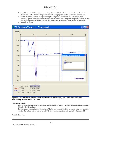
Tektronix, Inc.5. Use Z-line tool of IConnect to compute impedance profile. Set Zo equal to 100 Ohm and press the“Compute” Button. The resulting waveform will be displayed in the time domain viewer window.6. Enable IConnect’s cursors by right-clicking the computed Z-waveforms and selecting “CursorReadout” option. Using the cursors measure the impedance value at a point 2 ns past the bottom of thelast major capacitive excursion (i.e. dip) that is known to be inside the ASIC device (Figure 2.1).7. Record the results.Figure 2.1 Pair differential impedance measurements for transmitter (TX01). The impedance valuemeasured by the blue cursor is 87 Ohm.Observable Results:The Pair Differential Impedance minimum and maximum for the PUT TX port shall be between 85 and 115Ohms for Gen1i, products.The impedance measured at the time value of 2nSec past the bottom of the last major capacitive excursion(i.e. dip) that is known to be inside the ASIC device constitutes an informative result. See figure 2.1.Possible Problems:<strong>SATA</strong> Rx/Tx MOI Revision 1.1 ver <strong>1.0</strong>9