AASHTO Design Criteria Applied to Hydraulic Bascule Bridges
AASHTO Design Criteria Applied to Hydraulic Bascule Bridges
AASHTO Design Criteria Applied to Hydraulic Bascule Bridges
Create successful ePaper yourself
Turn your PDF publications into a flip-book with our unique Google optimized e-Paper software.
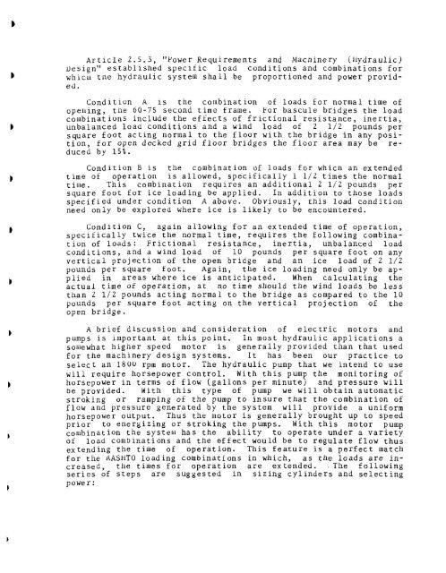
Article 2.5.3, "Power Requirements and Machinery (<strong>Hydraulic</strong>)uesign" established specific load conditions and combinations forwhicu tne hydraulic system shall be proportioned and power provided.Condition A is tne combination of loads for normal time ofopening, the 60-75 second time frame. For bascule bridges the loadcombinations include the effects of frictional resistance, inertia,unbalanced load conditions and a wind load of 2 1/2 pounds persquare foot acting normal <strong>to</strong> the floor with the bridge in any position,for open decked grid floor bridges the floor area may be reducedby 15%.Condition B is the combination of loads for whicn an extendedtime of operation is allowed, specifically 1 1/2 times the nornaltime. This combination requires an additional 2 1/2 pounds persquare foot for ice loading be applied. In addition <strong>to</strong> those loadsspecified under condition A above. Obviously, this load conditionneed only be explored where ice is likely <strong>to</strong> be encountered.Condition C, again allowing for an extended time of operation,specifically twice the normal time, requires the following combinationof loads: Frictional resistance, inertia, unbalanced loadconditions, and a wind load of 10 pounds per square foot on anyvertical projection of the open bridge and an ice load of 2 1/2pounds per square foot. Again, the ice loading need only be appliedin areas where ice is anticipated. When calculating theactual time of operation, at no time should the wind loads be lessthan 2 1/2 pounds acting normal <strong>to</strong> the bridge as compared <strong>to</strong> the 10pounds per square foot acting on the vertical projection of theopen bridge.A brief discussion and consideration of electric mo<strong>to</strong>rs andpumps is important at this point. In most hydraulic applications asomewhat higher speed mo<strong>to</strong>r is generally provided than that usedfor the machinery design systems. It has been our practice <strong>to</strong>select an 1800 rpm mo<strong>to</strong>r. The hydraulic pump that we intend <strong>to</strong> usewill require horsepower control. With this pump the moni<strong>to</strong>ring ofhorsepower in terms of flow (gallons per minute) and pressure willbe provided. With this type of pump we will obtain au<strong>to</strong>maticstroking or ramping of the pump <strong>to</strong> insure that the combination offlow and pressure generated by the system will provide a uniformhorsepower output. Thus the mo<strong>to</strong>r is generally brought up <strong>to</strong> speedprior <strong>to</strong> energizing or stroking the pumps. With this mo<strong>to</strong>r pumpcombination the system has the ability <strong>to</strong> operate under a varietyof load combinations and the effect would be <strong>to</strong> regulate flow thusextending the time of operation. This feature is a perfect matchfor the <strong>AASHTO</strong> loading combinations in which, as the loads are increased,the times for operation are extended. . The followingseries of steps are suggested in sizing cylinders and selectingpower:


