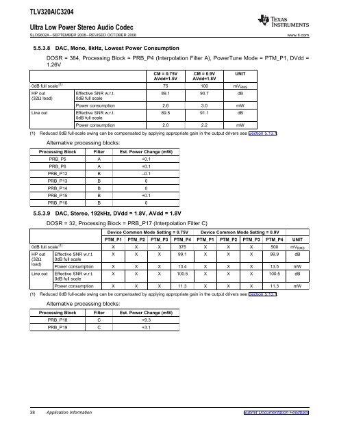
TLV320AIC3204<strong>Ultra</strong> <strong>Low</strong> <strong>Power</strong> <strong>Stereo</strong> <strong>Audio</strong> <strong>Codec</strong>SLOS602A–SEPTEMBER 2008–REVISED OCTOBER 2008www.ti.com5.5.3.8 DAC, Mono, 8kHz, <strong>Low</strong>est <strong>Power</strong> ConsumptionDOSR = 384, Processing Block = PRB_P4 (Interpolation Filter A), <strong>Power</strong>Tune Mode = PTM_P1, DVdd =1.26V5.5.3.9 DAC, <strong>Stereo</strong>, 192kHz, DVdd = 1.8V, AVdd = 1.8VCM = 0.75V CM = 0.9V UNITAVdd=1.5V AVdd=1.8V0dB full scale (1) 75 100 mV RMSHP out Effective SNR w.r.t. 89.1 90.7 dB(32Ω load) 0dB full scale<strong>Power</strong> consumption 2.6 3.0 mWLine out Effective SNR w.r.t. 89.5 91.1 dB0dB full scale<strong>Power</strong> consumption 2.0 2.2 mW(1) Reduced 0dB full-scale swing can be compensated by applying appropriate gain in the output drivers see Section 5.13.1.Alternative processing blocks:Processing Block Filter Est. <strong>Power</strong> Change (mW)PRB_P5 A +0.1PRB_P6 A +0.1PRB_P12 B –0.1PRB_P13 B 0PRB_P14 B 0PRB_P15 B +0.1PRB_P16 B 0DOSR = 32, Processing Block = PRB_P17 (Interpolation Filter C)Device Common Mode Setting = 0.75V Device Common Mode Setting = 0.9VPTM_P1 PTM_P2 PTM_P3 PTM_P4 PTM_P1 PTM_P2 PTM_P3 PTM_P4 UNIT0dB full scale (1) X X X 375 X X X 500 mV RMSHP out Effective SNR w.r.t. X X X 99.1 X X X 99.9 dB(32Ω 0dB full scaleload)<strong>Power</strong> consumption X X X 13.4 X X X 13.5 mWLine out Effective SNR w.r.t. X X X 100.5 X X X 100.5 dB0dB full scale<strong>Power</strong> consumption X X X 11.3 X X X 11.3 mW(1) Reduced 0dB full-scale swing can be compensated by applying appropriate gain in the output drivers see Section 5.13.1.Alternative processing blocks:Processing Block Filter Est. <strong>Power</strong> Change (mW)PRB_P18 C +9.3PRB_P19 C +3.138 Application InformationSubmit Documentation Feedback
5.5.3.10 DAC, <strong>Stereo</strong>, 192kHz, <strong>Low</strong>est <strong>Power</strong> ConsumptionTLV320AIC3204<strong>Ultra</strong> <strong>Low</strong> <strong>Power</strong> <strong>Stereo</strong> <strong>Audio</strong> <strong>Codec</strong>www.ti.com SLOS602A–SEPTEMBER 2008–REVISED OCTOBER 2008DOSR = 16, Processing Block = PRB_R17 (Interpolation Filter C), <strong>Power</strong>Tune Mode = PTM_P4, DVdd =1.26VCM = 0.75V CM = 0.9V UNITAVdd=1.5V AVdd=1.8V0dB full scale (1) 375 500 mV RMSHP out Effective SNR w.r.t. 99.4 100.3 dB(32Ω load) 0dB full scale<strong>Power</strong> consumption 7.7 8.9 mWLine out Effective SNR w.r.t. 100.4 100.4 dB0dB full scale<strong>Power</strong> consumption 6.1 6.7 mW(1) Reduced 0dB full-scale swing can be compensated by applying appropriate gain in the output drivers see Section 5.13.1.Alternative processing blocks:Processing Block Filter Est. <strong>Power</strong> Change (mW)PRB_P18 C +4.5PRB_P19 C +1.55.6 ADC5.6.1 ConceptThe TLV320AIC3204 includes a stereo audio ADC, which uses a delta-sigma modulator with aprogrammable oversampling ratio, followed by a digital decimation filter. The ADC supports sampling ratesfrom 8kHz to 192kHz. In order to provide optimal system power management, the stereo ADC can bepowered up one channel at a time, to support the case where only mono record capability is required. Inaddition, both channels can be fully powered or entirely powered down. Because of the oversamplingnature of the audio ADC and the integrated digital decimation filtering, requirements for analoganti-aliasing filtering are very relaxed. The TLV320AIC3204 integrates a second order analog anti-aliasingfilter with 28-dB attenuation at 6MHz. This filter, combined with the digital decimation filter, providessufficient anti-aliasing filtering without requiring additional external components.5.6.2 RoutingAs shown in Figure 5-2, the TLV320AIC3204 includes six analog inputs which can be configured as either3 stereo single-ended pairs or 3 fully-differential pairs. These pins connect through series resistors andswitches to the virtual ground terminals of two fully-differential amplifiers (one per ADC/PGA channel). Byturning on only one set of switches per amplifier at a time, the inputs can be effectively multiplexed toeach ADC PGA channel. By turning on multiple sets of switches per amplifier at a time, audio sources canbe mixed. The TLV320AIC3204 supports the ability to mix up to four single-ended analog inputs or up totwo fully-differential analog inputs into each ADC PGA channel.In most applications, high input impedance is desired for analog inputs. However when used inconjunction with high gain as in the case of microphone inputs, the higher input impedance results inhigher noise or lower dynamic range. The TLV320AIC3204 allows the user the flexibility of choosing theinput impedance from 10kΩ, 20kΩ and 40kΩ. When multiple inputs are mixed together, by choosingdifferent input impedances, level adjustment can be achieved. For example, if one input is selected with10kΩ input impedance and the second input is selected with 20kΩ input impedance, then the second inputis attenuated by half as compared to the first input. Note that this input level control is not intended to be avolume control, but instead used occasionally for level setting.Mixing of multiple inputs can easily lead to PGA outputs that exceed the range of the internal amplifiers,resulting in saturation and clipping of the mixed output signal. Whenever mixing is being implemented, thesystem designer is advised to take adequate precautions to avoid such a saturation from occurring. Ingeneral, the mixed signal should not exceed 0dB.Submit Documentation Feedback Application Information 39
- Page 1 and 2: LDO inLDO SelectAVddDVddIOVddAVssDV
- Page 3 and 4: LORLOLIN3_RIN3_LMICBIASREFTLV320AIC
- Page 5 and 6: TLV320AIC3204Ultra Low Power Stereo
- Page 7 and 8: 3.3 ELECTRICAL CHARACTERISTICSTLV32
- Page 9 and 10: TLV320AIC3204Ultra Low Power Stereo
- Page 11 and 12: TLV320AIC3204Ultra Low Power Stereo
- Page 13 and 14: All numbers are from characterizati
- Page 15 and 16: 3.4.3.2 TYPICAL TIMING CHARACTERIST
- Page 17 and 18: 4 TYPICAL CHARACTERISTICS4.1 TYPICA
- Page 19 and 20: 4.2 FFTTLV320AIC3204Ultra Low Power
- Page 21 and 22: 5 Application Information5.1 TYPICA
- Page 23 and 24: 5.2.6 Register Settings for Multifu
- Page 25 and 26: 5.3 ANALOG ROUTINGTLV320AIC3204Ultr
- Page 27 and 28: 5.5 POWERTUNE5.5.1 PowerTune Modes5
- Page 29 and 30: 5.5.2.4 ADC, Mono, 48kHz, Highest P
- Page 31 and 32: 5.5.2.9 ADC, Stereo, 8kHz, Lowest P
- Page 33 and 34: 5.5.2.14 ADC, Stereo, 192kHz, Lowes
- Page 35 and 36: 5.5.3.2 DAC, Stereo, 48kHz, Lowest
- Page 37: 5.5.3.6 DAC, Stereo, 8kHz, Lowest P
- Page 41 and 42: 5.7.2 Digital Volume Control5.7.3 F
- Page 43 and 44: NH(z) 2023 N D11z11zTLV320AIC3204Ul
- Page 45 and 46: 5.8 ADC Decimation Filtering and Si
- Page 47 and 48: 5.8.2.5 3 Biquads, 1 st order IIR,
- Page 49 and 50: 5.8.3.2 Biquad SectionNH(z) 2023 2
- Page 51 and 52: 5.8.4.1 Decimation Filter ATLV320AI
- Page 53 and 54: 5.8.4.3 Decimation Filter CTLV320AI
- Page 55 and 56: TLV320AIC3204Ultra Low Power Stereo
- Page 57 and 58: 5.9.7 Adaptive FilteringTLV320AIC32
- Page 59 and 60: TLV320AIC3204Ultra Low Power Stereo
- Page 61 and 62: 5.11.1 Processing BlocksTLV320AIC32
- Page 63 and 64: 5.11.2.6 4 Biquads, Filter BTLV320A
- Page 65 and 66: 5.11.3 User Programmable Filters5.1
- Page 67 and 68: TLV320AIC3204Ultra Low Power Stereo
- Page 69 and 70: TLV320AIC3204Ultra Low Power Stereo
- Page 71 and 72: 5.12.2 Headphone Amplifier Class-D
- Page 73 and 74: TLV320AIC3204Ultra Low Power Stereo
- Page 75 and 76: 5.13.3.1 DRC Threshold5.13.3.2 DRC
- Page 77 and 78: 5.14.2 DIGITAL AUTO MUTE5.14.3 Adap
- Page 79 and 80: 5.16 CLOCK GENERATION AND PLLTLV320
- Page 81 and 82: TLV320AIC3204Ultra Low Power Stereo
- Page 83 and 84: 5.16.1 PLLTLV320AIC3204Ultra Low Po
- Page 85 and 86: 5.17 INTERFACE5.17.1 AUDIO DIGITAL
- Page 87 and 88: TLV320AIC3204Ultra Low Power Stereo
- Page 89 and 90:
TLV320AIC3204Ultra Low Power Stereo
- Page 91 and 92:
5.17.2.1 I 2 C CONTROL MODETLV320AI
- Page 93 and 94:
TLV320AIC3204Ultra Low Power Stereo
- Page 95 and 96:
5.18.1.3 Other Supply Options5.19 R
- Page 97 and 98:
TLV320AIC3204Ultra Low Power Stereo
- Page 99 and 100:
5.22.3 DAC Playback Through Class-D
- Page 101 and 102:
5.22.5 Stereo ADC with 48ksps Sampl
- Page 103 and 104:
6 REGISTER MAP6.1 Register Map Summ
- Page 105 and 106:
6.2.9 Page 0 / Register 8: Clock Se
- Page 107 and 108:
6.2.19 Page 0 / Register 19: Clock
- Page 109 and 110:
6.2.29 Page 0 / Register 29: Audio
- Page 111 and 112:
6.2.36 Page 0 / Register 36: ADC Fl
- Page 113 and 114:
6.2.43 Page 0 / Register 45: Sticky
- Page 115 and 116:
TLV320AIC3204Ultra Low Power Stereo
- Page 117 and 118:
6.2.54 Page 0 / Register 57-59: Res
- Page 119 and 120:
6.2.61 Page 0 / Register 66: Right
- Page 121 and 122:
6.2.67 Page 0 / Register 72: Beep G
- Page 123 and 124:
6.2.79 Page 0 / Register 84: Right
- Page 125 and 126:
6.2.85 Page 0 / Register 90: Left C
- Page 127 and 128:
6.2.92 Page 0 / Register 97: Right
- Page 129 and 130:
6.2.98 Page 0 / Register 103: DC Me
- Page 131 and 132:
6.2.109 Page 1 / Register 3: Playba
- Page 133 and 134:
6.2.117 Page 1 / Register 14: LOL R
- Page 135 and 136:
TLV320AIC3204Ultra Low Power Stereo
- Page 137 and 138:
TLV320AIC3204Ultra Low Power Stereo
- Page 139 and 140:
TLV320AIC3204Ultra Low Power Stereo
- Page 141 and 142:
TLV320AIC3204Ultra Low Power Stereo
- Page 143 and 144:
6.2.134 Page 1 / Register 55: Right
- Page 145 and 146:
6.2.141 Page 1 / Register 62: ADC A
- Page 147 and 148:
6.2.152 Page 9-16 / Register 0: Pag
- Page 149 and 150:
6.2.167 Page 62-70 / Register 8-127
- Page 151 and 152:
TLV320AIC3204Ultra Low Power Stereo
- Page 153 and 154:
PACKAGE OPTION ADDENDUMwww.ti.com26
- Page 155:
PACKAGE MATERIALS INFORMATIONwww.ti