TMdrive®-30 Product Application Guide - Tmeic.com
TMdrive®-30 Product Application Guide - Tmeic.com
TMdrive®-30 Product Application Guide - Tmeic.com
- No tags were found...

Create successful ePaper yourself
Turn your PDF publications into a flip-book with our unique Google optimized e-Paper software.
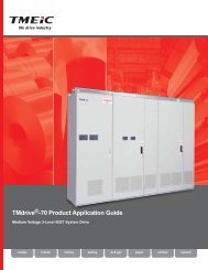
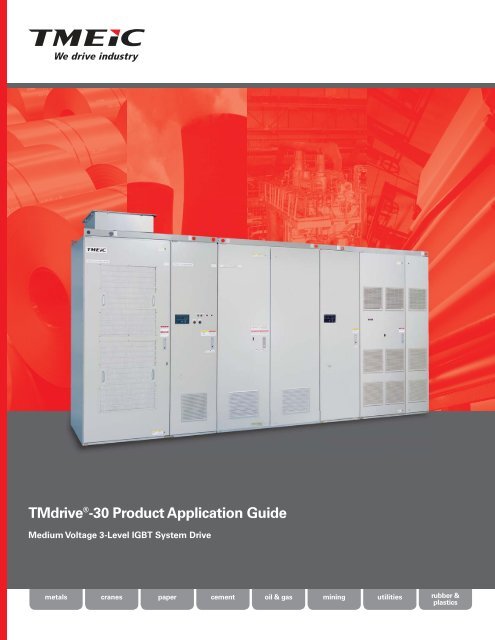
TMdrive ® -<strong>30</strong> <strong>Product</strong> <strong>Application</strong> <strong>Guide</strong>Medium Voltage 3-Level IGBT System Drivemetalscranespapercementoil & gasminingutilitiesrubber &plastics
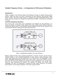
A Look InsideReliable medium voltagedc-fed system drive technologyfor high power applications:• Heat pipe coolingtechnology that reducesthe size of the power bridgeand audible noise generatedby the cooling fans• Modular phase-legassemblies mountedon heavy-duty slides thatreduce the time required formaintenanceI/O BoardThe I/O board supports an encoder, 24 V dc I/O, 115 V ac inputs, andanalog I/O, standard. In addition, a resolver interface option can beprovided. All I/O are terminated toa two-piece modular terminal blockfor ease of maintenance.3<strong>30</strong>0 FrameConverterTM-<strong>30</strong> Capacitor• Common controlhardware that lowers the costof spare parts inventoryThyristor BridgeA 12-pulse input sectionprovides good harmonicperformance for the thyristorconverter. Forward andreverse conducting devicesallow both motoring andregenerative operation. The converteralso provides smooth charging anddischarging of the dc bus to controlinrush and enhance safety.In<strong>com</strong>ing Power(Main and Control)The converter in each lineupis fed 6-phase ac power.Main power connections arelocated in the rear of the TMdrive-T<strong>30</strong>converter. Only bottom access entryis supported. In addition, 3-phase accontrol power is fed to each converterand inverter control cabinet. A controlpower disconnect is provided in eachcabinet.Capacitor and Bus Interface PanelThe TMdrive-<strong>30</strong> capacitor panel is usedto provide an electrical interface with theTMdrive-<strong>30</strong> inverter. Remotely mounteddc link reactors are wired betweenthese connections. In addition, each TMdrive-<strong>30</strong>inverter phase leg has a set of capacitors that arehoused in a modular draw-out unit for ease ofmaintenance.2
Control FunctionsEach inverter and regenerative convertershares a <strong>com</strong>mon set of control boards.The primary control board performsseveral functions:• Speed and torque regulation• Sequencing• I/O mapping• Diagnostic data gatheringA mounting bracket is provided for anoptional LAN interface board.Panel2000 Frame InverterIGBT Three-LevelPhase-leg AssemblyThe inverters and IGBTbasedsources havemodular three-level phaseleg assemblies. Each phaseleg includes:• IGBTs with flyback diodes• Heatpipe assembly• IGBT gate driver circuit board• Heavy-duty slides that allow easyaccess for maintenance activities• High-speed fusesNPCommon DC BusThe dc converter in each lineup generates dc power foreach of the inverters. The inverters then create variablefrequency ac power to control the induction motors. This dcpower for the lineup is conveyed on a copper bus bar systemlocated in the bottom of the cabinets. This design allowsmultiple inverters to be powered from a single converter.Motor Bus TabsEach phase leg has a motorbus tab located at the bottomof the modular phase leg.3
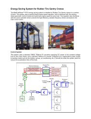
A Wide Variety of Power Bridgesfor Every <strong>Application</strong>TMdrive–D<strong>30</strong> Non-Regenerative Diode ConverterTMdrive–P<strong>30</strong> Regenerative IGBTTransientSuppressionMain CircuitFusesInternal dcLink Reactors3400 FrameCircuitBreaker670 V ac900 V dcNP2000 Frame670 V ac900 V dcCircuitBreaker1100 V acControlPowerControlTMdrive–T<strong>30</strong> Regenerative Thyristor ConverterDC Bus Charging CircuitControlControlPower+CircuitBreaker900 V ac900 V dc3<strong>30</strong>0 Frame900 V acNPControlCurrent andVoltage Sensors900 V dc4000 Frame-Optional acLink ReactorCapacitor panelintegral withinverter lineupExternal dcLink ReactorsCapacitor PanelIntegral withInverter Lineup1100 V ac6000 FrameCircuitBreaker900 V acInternal LoadSharing ReactorsFuses+900 V dcCircuitBreakerControlPower900 V acNP1100 V acControlCurrent andVoltage Sensors900 V dcOptional acLink Reactor-ControlOptional Reversing ThyristorStack On Second Bank4
ConverterTMdrive–<strong>30</strong> IGBT Inverter++1500 and2000 Frame900 V dcNP1250 V acM3NP900 V dc--Initial Charging Circuit+<strong>30</strong>00 and 4000 FrameNP1250 V ac+Dual WindingInduction Motor900 V dc-Optional MotorIsolation SwitchesM6NP900 V dc1250 V ac-CombiningOutput ReactorM3Optional Configuration usingThree-phase Induction Motor5
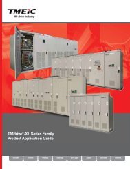
Converter Specifications2375 mm (94 in)2600 mm (103 in)2600 mm (103 in)2406 mm (95 in)2406 mm (95 in)Non-Regenerative Diode (TMdrive-D<strong>30</strong>)2200 mm (87 in)Regenerative Thyristor (TMdrive-T<strong>30</strong>)2<strong>30</strong>0 mm (91 in)1600 mm (63 in) 1200 mm (47 in)2600 mm (102 in) 1200 mm (47 in)Regenerative IGBT (TMdrive-P<strong>30</strong>)2200 mm (87 in)3400 mm (134 in)2<strong>30</strong>0 mm (91 in)FrameWeightkg (lbs)Full LoadLosses kWControlPowerva22003400 15 800(4840)<strong>30</strong>003<strong>30</strong>0 21 1500(6600)3<strong>30</strong>06000 41 2400(7260)16002000 25 1000(3520)26004000 50 2000(5720)ConverterOutput PowerkW (hp)3<strong>30</strong>0(4424)3<strong>30</strong>0(4424)6000(8043)1733(2323)3465(4645)CurrentA acCurrentA dcAllowableOverload %1496 1895 150-60s1316 1613 175-60s1182 1448 200-60s972 1191 250-60s807 989 <strong>30</strong>0-60s1496 1833 150-10s1426 1747 200-10s1253 1535 250-10s1110 1360 <strong>30</strong>0-10s1496 1833 150-60s1236 1515 200-60s1044 1280 250-60s898 1100 <strong>30</strong>0-60s2720 3333 150-10s2566 3144 200-10s2255 2763 250-10s2007 2460 <strong>30</strong>0-10s2720 3333 150-60s2225 2727 200-60s1877 2<strong>30</strong>0 250-60s1616 1980 <strong>30</strong>0-60s929 963 150-60s796 825 175-60s697 722 200-60s557 577 250-60s465 482 <strong>30</strong>0-60s1858 1925 150-60s1593 1650 175-60s1394 1444 200-60s1115 1155 250-60s929 963 <strong>30</strong>0-60sNon-Regenerative Converter (TMdrive–D<strong>30</strong>) ExampleWhen specifying a converter, start from the process requirements and work through the motor to the inverter, and then theassociated converter. The following example illustrates this process (continuation of inverter application example on page 9).6Compute the operating voltage1of the dc bus. It is assumed thatthe converter is dedicated tothe inverter specified in the applicationexample on page 9.V dc Bus= 1.35 x V Converter line-to-line=1.35 x 700= 900 V2Compute the continuous dc3current requirement of theconverter based on its powerrequirement.= 1500 kW x 10000.954 x 0.98 x 900 x 2= 891 ampsI dc Converter = kW Shaft x 1000Eff Mtr x Eff Inv x V dc Bus x 2Scan the specifications in the nonregenerativeconverter table above fora frame where the continuous currentrating exceeds 891 amps. The 3400 frame meetsthis criterion (1895amps), thus isthe appropriatenon-regenerativeconverter for thisapplication.Currentdc1895161314481191989Overload –Time150% – 60s175% – 60s200% – 60s250% – 60s<strong>30</strong>0% – 60s
Regenerative Converter (TMdrive–P<strong>30</strong>) ExampleWhen specifying a converter, start from the process requirements and work through the motor to the inverter, and then theassociated converter. The following example illustrates this process (continuation of inverter application example on page 9):1Compute kW requirementsinto the inverter. It isassumed that the converteris dedicated to the inverter specifiedin the application example onpage 9. It is also assumed that theconverter is controlled to unitypower factor.kW dc= kW ShaftEff Mtr2I ac ConverterCompute continuous ac current requirement of3the converter based on its power requirements.= kW dc x 10003 x V Converter line-to-line voltage x Eff Converter x Eff Inverter= 1580 kW x 10003 x 1100 V x 0.985 x 0.98 x 2= 4<strong>30</strong> amps= 1500 kWNote: For sizing systems with peak powers in regenerative mode,a different equation is used to <strong>com</strong>pute power requirements.0.954= 1580 kW kW dc = kW Shaft x (Eff Mtr x Eff Inverter )MiscellaneousScan the regenerativeconverter table for entries thatexceeds your overload (175%),time (60 sec) and continuous currentrequirements (4<strong>30</strong> amps). In this casethe 2000 frame TMdrive-P<strong>30</strong> meets therequirement and is appropriate for thisapplication.CurrentA ac1858159313941115929Overload –Time150% – 60s175% – 60s200% – 60s250% – 60s<strong>30</strong>0% – 60sMain Circuit Input Voltage Variation ± 10%Input Frequency 50/60 Hz ±20%TMdrive-P<strong>30</strong> Input Chopping1.5 kHzControl Power180-220 V ac, 50 Hz 3-phase198-242 V ac, 60 Hz 3-phaseDisplacement Power TMdrive-D<strong>30</strong> - 0.98Factor (at all loads) TMdrive-T<strong>30</strong> - 0.71 to 0.98depending on applicationTMdrive-P<strong>30</strong> - Unity power factorConverter Notes1. TMdrive-D<strong>30</strong> and TMdrive-P<strong>30</strong> converters and TMdrive-T<strong>30</strong>capacitor panels are 800mm (32in) in depth. TMdrive-T<strong>30</strong> thyristorpanels are 1000mm (40in) in depth.2. Allocate a minimum of 500mm (20 in) above the cabinet for anmaintenance. All equipment requires a steel support of at least 50mm(2 in) under the panel which is not included in these dimensions.3. The specified current ratings are continuous to which the referencedoverload can be applied. Refer to the application example.4. All TMdrive-<strong>30</strong> equipment supports bottom cable entry standard. Topcable entry is support with adjacent auxiliary cabinets.5. All TMdrive-<strong>30</strong> equipment requires 3-phase control power and thekVA requirements shown in the rating tables are continuous. Inaddition, TMdrive-D<strong>30</strong> and TMdrive-P<strong>30</strong> converters have additionaltransient bus charging requirements of <strong>30</strong> amps peak.6. All TMdrive-<strong>30</strong> converters require an external circuit breaker.7. TMdrive-T<strong>30</strong> converters require external dc link reactors.TMdrive-P<strong>30</strong> converters require external ac link reactors or highimpendence transformer.8. TMdrive-<strong>30</strong> converters pull air in the front and exhaust out the top ofcabinets.9. TMdrive-<strong>30</strong> dc <strong>com</strong>mon bus is limited to 1640 amps.10. TMdrive-P<strong>30</strong> and TMdrive-T<strong>30</strong> require ac-phase rotation to matchsystem elementaries.11. There are no restrictions on the total dc bus length or the minimumcapacitance connected to any of these converters. For maximumcapacitance consult the factory when the <strong>com</strong>bined capacity of allconnected inverters exceeds 1 times the rating of the TMdrive-P<strong>30</strong>converters or 2.5 times the rating of the TMdrive-D<strong>30</strong> converter.There are no maximum capacitance restrictions for the TMdrive-T<strong>30</strong>converter.12. TMdrive-D<strong>30</strong> and TMdrive-T<strong>30</strong> losses are proportional to loadcurrent. TMdrive-P<strong>30</strong> losses are 40% fixed with the remaining lossesproportional to current. Converter efficiency can be estimated at anyload by properly <strong>com</strong>bining static and load related losses.13. The maximum shipping split for TMdrive-<strong>30</strong> equipment is 3 m (118 in).14. TMdrive-P<strong>30</strong> converters require 1<strong>30</strong>0mm (51 in) minimum frontaccess and 50 mm (3 in) back clearance. Other converters require1050 mm (41 in) minimum access front and back.15. TMdrive-P<strong>30</strong> converters require isolation transformers with single ordual secondaries and optional ac reactor for total impedance of 12%.16. High temperature current derating: -2.5% per ˚C above 40 ˚C forTMdrive-T<strong>30</strong> and TMdrive-D<strong>30</strong> converters. No high temperaturederating for TMdrive-P<strong>30</strong> converters.17. Low temperature current derating: -1.75% per ˚C below 0 ˚Cfor TMdrive-P<strong>30</strong> converters. No derating for TMdrive-T<strong>30</strong> orTMdrive-D<strong>30</strong> converters.7
Inverter SpecificationsFrameWeightkg (lbs)Full LoadLosseskWControlPowervaInverterOutputKVAMotorOutput PowerkW (hp)MotorCurrentA acAllowableOverload%IGBT Inverter (TMdrive-<strong>30</strong>)2406 mm (95 in)1<strong>30</strong>02000 25 1000 2000(2860)1615(2165)924 150792 175693 200554 2501800 mm (71 in)462 <strong>30</strong>02406 mm (95 in)2<strong>30</strong>04000 50 2000 4000(5060)32<strong>30</strong>(43<strong>30</strong>)1848 1501584 1751386 2001109 250<strong>30</strong>00 mm (118 in)924 <strong>30</strong>0Inverter ExampleWhen specifying an inverter, start from the process requirements and work through the motor to the inverter.The following example illustrates this process.1Define processrequirements.kW Shaft = 1500 kW(2000 hp)The motor delivers constant torque fromzero to base speed of 900 rpm and 1500 kW(2000 hp).Duty cycle requires 175% for 10 sec. but hasrms duty cycle of 1500 kW (2000 hp).2Select motor based onprocess requirements and<strong>com</strong>pute required inverterkVA.• 1500 kW (2000 hp)• 900 rpm, 1200 V• Efficiency = 0.954• Power factor = 0.765• Service factor = 1.15Compute continuous3current requirementsfor the inverter basedon the selected motor.I ac Inverter = kW Shaft x 1000 x SF MtrEff Mtr x PF Mtr x 3 x V Motor rated voltageCurrent= 1500 x 1000 x 1.150.954 x 0.765 x 3 x 1200 VA ac13864Select inverter based oncontinuous current andoverload requirements.Scan the 175% entries in theinverter tables for a frame wherethe continuous current ratingexceeds 1138 amps.The <strong>30</strong>00 frame meets thiscriterion (1188 amps) and isappropriate for this application.11881040832693AllowableOverload %150175200250<strong>30</strong>08
Output VoltageOutput FrequencyOutput ChoppingFrequencyInverter TypeModulationInverter Power OutputPower SemiconductorTechnologyEnclosureCableEntranceWire ColorsShort Circuit RatingsAcoustic NoiseMean Time to RepairMTBFCode Conformance0-1250 V0-120 HzContinuous operation below0.4 Hz requires derate1.5 kHz3-level voltage converterPulse Width Modulation(PWM)Insulated Gate BipolarTransistor (IGBT)Mechanical (Inverters and Converters)NEMA 1 (IP20) IP32 or IP31 optionalBottom is standardTop with optional auxiliary cabinetPer CSA/UL and CE100 kA for ac and dc buswork10 kA for control power≤ 68 dB<strong>30</strong> minutes to replacepower bridge phase-leg> 41,000 hoursApplicable IEC, JIS, JEM, UL,CSA and NEMA standardsWith Speed Sensor (Resolver or Encoder)Speed regulator accuracy: +/- 0.01%Maximum speed response: 60 rad/secTorque linearity: +/- 3% with temperature sensor+/- 10% without temperature sensorMaximum Torque current response: 1000 rad/secTorque range: 0-400% of rated motor torqueMaximum flux control range: 20%-100%Without Speed SensorSpeed regulator accuracy: +/- 0.1% with temperature sensor+/- 0.2% without temperature sensor(Using 1% slip motor at rated flux)Maximum speed regulator response: 20 rad/secMinimum continuous speed: 3%Torque linearity: +/-10%Maximum Torque current response: 1000 rad/secTorque range: 0-150% of rated motor torqueMaximum flux control range: 75%-100%OperatingTemperatureStorageTemperatureHumidityAltitudeMotor ControlEnvironmental (Inverters and Converters)0 to 40°C (32 to 104°F) at rated load-20 to 50°C (-4 to 122°F) with derating-25 to 55°C (-13 to 131°F)5 to 95% relative humidityNon-condensing0 to 5000 m (16,400 ft) above sea levelDerate voltage 2.25% per 200 m (656 ft) above1800 m (5905 ft)Derate TMdrive-<strong>30</strong> and TMdrive-P<strong>30</strong> current1% per 200 m (656 ft) above 3500 m (11,480 ft)Derate TMdrive-T<strong>30</strong> and TMdrive-D<strong>30</strong> current1% per 200 m (656 ft) above 1000 m (3280 ft)Vibration 10-50 Hz,
Operator InterfacesStandard Display (Inverters and Regenerative Converters)Three-digit display alternates between speed and current whilerunning, or a fault code when there is an error.Three LEDs give aquick indication ofthe status ofthe unitOptional analog meters can besupplied in addition to either thestandard or enhanced display.For cabinet style equipment, fourmeters are provided.RJ-45 Ethernet port is used for localtoolbox connectionInterlock buttondisables the driveLED IndicationReady On when the unit isready to runRunning On when the unit isrunningAlarm/Fault Blinking LED indicatesalarm condition, whilesolid LED indicates afaultKeypad Option (Inverters and Regenerative Converters)High Function Display• LCD backlight givesgreat visibility andlong life• Bar graphs, icons,menus, and digitalvalues <strong>com</strong>bine toprovide concise statusinformation, ofteneliminating the needfor traditional analogmetersRJ-45 Ethernetport is used for the localtoolbox connectionInstrumentation Interface• Two analog outputs are dedicated to motorcurrent feedback• Five analog outputs can be mapped to variablesfor external data logging and analysisNon-Regenerative Converters (TMdrive–D<strong>30</strong>)Interlock buttondisables the driveEasy-to-understandnavigation buttonsallow quick accessto informationwithout resorting toa PC-based toolSwitch to localmode and operatethe equipment rightfrom the keypadBus Charged Indicator10Controls• Precharge circuit• ”On/Off” switch• ”Reset/Fault” switchIndicating Lamps• Green — ac breaker open• White — ac breaker closed• Yellow — precharging• Red — fault• Orange — alarm
A Common Control toReduce Cost of OwnershipFeedback And Status I/O Mapping Capture Buffer SequencingSpeedReferenceSpeedFeedbackConfigurationMeter OutputsDigital InputsDigital OutputsAnalog InputsAnalog Outputs(Optional)Speed FeedbackResolver InputSpeed FeedbackEncoder InputSpeed TachFollower OutputMotorTemperatureFeedbackControl FunctionsSpeed/TorqueInstrumentation InterfaceD/A+24 V dc24-110 V dc48-120 V ac10 V, 4-20 mAD/A+50 V dcSinCosSinCosAB+15-48 V+ - 10 VI/O InterfaceM10 VA/DFdbk ExcitnABZSupply ExcitnMotor ControlPWM• RJ-45 Ethernet interface• 10 Mbps maximum• Drive Navigator option ofTOSLINE -S20 to Ethernetconnection using V-Seriescontroller as gateway• Toolbox option of ISBus to Ethernet using InnovationSeries controller as gateway• Motor current A and B, ±10 V• Quantity 5 configurable, ±10 V,8-bit resolution• Opto-coupled 20 mA• Quantity 6 configurable mapping• Opto-coupled 10 mA• Quantity 1 configurable mapping• Quantity 1 dedicated mapping• Open collector 70 mA• Quantity 6 user defined• Quantity 2 ±10 V or 4-20 mA- Differential 8 kΩ input impedance- 12-bit resolution• Optional Quantity 2 ±10 V- 12 bit resolution(Optional forInverters only)• Quantity 3 ±10 V, 10 mA max• User defined• 8-bit resolution• Excitation frequency of 1 or 4 kHz• Source for resolvers is Tamagawa:www.tamagawa-seiki.co.jp• A quad B with marker• Maximum frequency of 100 kHz• Differential 5 or 15 V dc• 5 or 15 V dc at 200 mA supply• Maximum frequency of 10 kHz• External 15-24 V dc at100 mA max• High-resolution torque motortemperature feedback• 1 kΩ positive temperature coefficientRTD or other sensor using optionalsignal conditioning moduleTOSLINE-S20• Supports run-time control (6 words in and 10 words out) froman Innovation Series controller or V Series controller• Drives can directly exchange data between themselves (4words)• Fiber-optic bus in a star configuration• 2 Mbps peer-to-peer protocol; bus scan time based on thenumber of nodes:Quantity of Nodes Bus Scan Time2-3 1 ms4-5 2 ms6-8 4 ms9-64 25 msISBus• Supports both run-time control (10 words in and 10 words out)and Toolbox configuration/monitoring using the InnovationSeries controller as a gateway between the ISBus & Ethernet• RS-485 or optional fiber-optic bus in a synchronous ringconfiguration• 5 Mbps master/follower (drive is the follower) protocolusing copper or fiber; bus scan time based on the numberof nodes:Quantity of Nodes Bus Scan Time2-4 1 ms5-8 2 ms6 -16 4 ms17-32 8 msModbus• Supports run-time control (fixed 10 words in/out) from aModbus-RTU controller• RS-485 copper bus• 1.2 kbps to 57.6 kbps master/follower protocol; update ratesup to 20 ms/node possible at the highest baud rate• Number of notes: 127 max per LANMELPLAC Net• Supports run-time control (8 words in and out) fromMELPLAC Net master controller• Fiber-optic bus• 1 Mbps peer-to-peer protocol, cyclic transmission• Number of nodes: 128 local station maxProfibus-DP • Supports run-time control (6 words in and 10 out) from aProfibus-DP master controller• Copper bus in a daisy-chain configuration• 9.6 kbps to 12 Mbps master/follower protocol; bus scan timebased on the number of nodesDeviceNet LAN Interface Options• Supports run-time control (4 words in and 10 words out)froma DeviceNet master controller• Copper bus in a daisy-chain configuration• 125 kbps to 500 kbps master/follower protocol; bus scantime based on the number of nodesNote: 1 word = 16 bits11
TMdrive System DrivesOffer Complete CoverageGlobal Office Locations:TOSHIBA MITSUBISHI-ELECTRIC INDUSTRIALSYSTEMS CORPORATIONMita 43 MT Bldg.13-16 Mita 3 chome, Minato-ku Tokyo108-0073 JapanTel.: +81-3-5444-3828Fax: +81-3-5444-3820Web: www.tmeic.co.jpTMEIC CorporationOffice: 1325 Electric Road, Suite 200Roanoke, VA, United States 24018Mailing: 2060 Cook DriveSalem, VA, United States 24153Tel.: +1-540-283-2000Fax: +1-540-283-2001Web: www.tmeic.<strong>com</strong>TMEIC Europe LimitedAlbany House, 71-79 Station RoadWest Drayton, Middlesex, United KingdomUB7 7LTTel.: +44 870 950 7220Fax: +44 870 950 7221Email: info@tmeic.euWeb: www.tmeic.<strong>com</strong>TOSHIBA MITSUBISHI-ELECTRIC INDUSTRIALSYSTEMS (Beijing) CORPORATION21/F., Building B, In.do Mansion48 Zhichunlu A, Haidian District,Beijing 100098, PRCTEL: +86 10 5873-2277Fax: +86 10 5873-2208Email: sales@tmeic-cn.<strong>com</strong>TMdrive is a registered trademark of Toshiba Mitsubishi-ElectricIndustrial Systems Corporation.All other products mentioned are registered trademarks and/or trademarks oftheir respective <strong>com</strong>panies.All specifications in this document are subject to change without notice. Theabove brochure is provided free of charge and without obligation to the reader orto TMEIC Corporation, and is for informational purposes only. TMEIC Corporationdoes not accept, nor imply, the acceptance of any liability with regard to theuse of the information provided. TMEIC Corporation provides the informationincluded herein as is and without warranty of any kind, express or implied,including but not limited to any implied statutory warranty of merchantabilityor fitness for particular purposes. The brochure is not an implied or expresscontract. If you have any questions regarding your project requirements, pleasecontact TMEIC Corporation at 540-283-2000.TMEIC Industrial Systems India Private LimitedUnit # 03-04, Third Floor,Block 2, Cyber Pearl, HITEC City, Madhapur,Hyderabad, 500081, Andhra Pradesh, IndiaTel: +91-40-4434-0000Fax: +91-40-4434-0034Email: inquiry_india@tmeic.<strong>com</strong>Web: www.tmeic.in© 2011 TMEIC Corporation, USA. All Rights ReservedP-1115