EPR – Areva brochure
EPR – Areva brochure
EPR – Areva brochure

You also want an ePaper? Increase the reach of your titles
YUMPU automatically turns print PDFs into web optimized ePapers that Google loves.
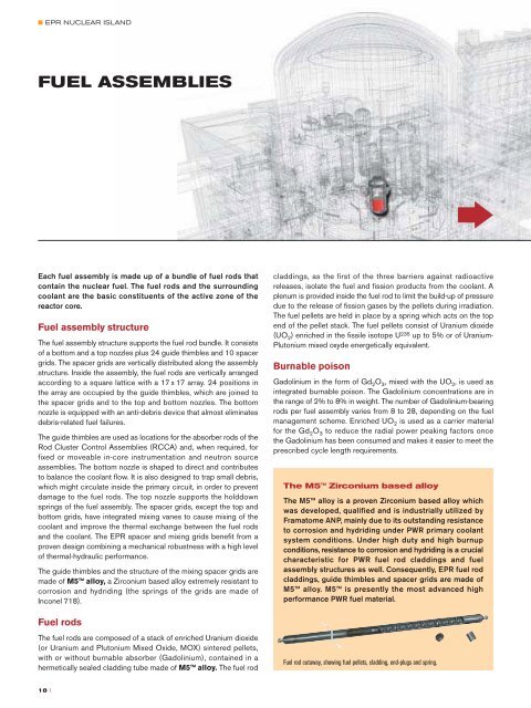
■ <strong>EPR</strong> NUCLEAR ISLAND17 x 17 fuel assemblyFUEL ASSEMBLIESEach fuel assembly is made up of a bundle of fuel rods thatcontain the nuclear fuel. The fuel rods and the surroundingcoolant are the basic constituents of the active zone of thereactor core.Fuel assembly structureThe fuel assembly structure supports the fuel rod bundle. It consistsof a bottom and a top nozzles plus 24 guide thimbles and 10 spacergrids. The spacer grids are vertically distributed along the assemblystructure. Inside the assembly, the fuel rods are vertically arrangedaccording to a square lattice with a 17 x 17 array. 24 positions inthe array are occupied by the guide thimbles, which are joined tothe spacer grids and to the top and bottom nozzles. The bottomnozzle is equipped with an anti-debris device that almost eliminatesdebris-related fuel failures.The guide thimbles are used as locations for the absorber rods of theRod Cluster Control Assemblies (RCCA) and, when required, forfixed or moveable in-core instrumentation and neutron sourceassemblies. The bottom nozzle is shaped to direct and contributesto balance the coolant flow. It is also designed to trap small debris,which might circulate inside the primary circuit, in order to preventdamage to the fuel rods. The top nozzle supports the holddownsprings of the fuel assembly. The spacer grids, except the top andbottom grids, have integrated mixing vanes to cause mixing of thecoolant and improve the thermal exchange between the fuel rodsand the coolant. The <strong>EPR</strong> spacer and mixing grids benefit from aproven design combining a mechanical robustness with a high levelof thermal-hydraulic performance.The guide thimbles and the structure of the mixing spacer grids aremade of M5 alloy, a Zirconium based alloy extremely resistant tocorrosion and hydriding (the springs of the grids are made ofInconel 718).Fuel rodsThe fuel rods are composed of a stack of enriched Uranium dioxide(or Uranium and Plutonium Mixed Oxide, MOX) sintered pellets,with or without burnable absorber (Gadolinium), contained in ahermetically sealed cladding tube made of M5 alloy. The fuel rodcladdings, as the first of the three barriers against radioactivereleases, isolate the fuel and fission products from the coolant. Aplenum is provided inside the fuel rod to limit the build-up of pressuredue to the release of fission gases by the pellets during irradiation.The fuel pellets are held in place by a spring which acts on the topend of the pellet stack. The fuel pellets consist of Uranium dioxide(UO 2 ) enriched in the fissile isotope U 235 up to 5% or of Uranium-Plutonium mixed oxyde energetically equivalent.Burnable poisonGadolinium in the form of Gd 2 O 3 , mixed with the UO 2 , is used asintegrated burnable poison. The Gadolinium concentrations are inthe range of 2% to 8% in weight. The number of Gadolinium-bearingrods per fuel assembly varies from 8 to 28, depending on the fuelmanagement scheme. Enriched UO 2 is used as a carrier materialfor the Gd 2 O 3 to reduce the radial power peaking factors oncethe Gadolinium has been consumed and makes it easier to meet theprescribed cycle length requirements.The M5 Zirconium based alloyThe M5 alloy is a proven Zirconium based alloy whichwas developed, qualified and is industrially utilized byFramatome ANP, mainly due to its outstanding resistanceto corrosion and hydriding under PWR primary coolantsystem conditions. Under high duty and high burnupconditions, resistance to corrosion and hydriding is a crucialcharacteristic for PWR fuel rod claddings and fuelassembly structures as well. Consequently, <strong>EPR</strong> fuel rodcladdings, guide thimbles and spacer grids are made ofM5 alloy. M5 is presently the most advanced highperformance PWR fuel material.Fuel rod cutaway, showing fuel pellets, cladding, end-plugs and spring.†CHARACTERISTICSDATAFuel assembliesFuel rod array 17 x 17Lattice pitch12.6 mmNumber of fuel rods per assembly 265Number of guide thimbles per assembly 24Fuel assembly discharge burnup (maximum) > 70,000 MWd/tMaterials<strong>–</strong> Mixing spacer grids• structureM5• springs Inconel 718<strong>–</strong> Top & bottom spacer grids Inconel 718<strong>–</strong> Guides thimbles M5<strong>–</strong> Nozzles Stainless steel<strong>–</strong> Holddown springs Inconel 718Fuel rodsOutside diameter9.50 mmActive length4,200 mmCladding thickness0.57 mmCladding materialM5† The U 235 enrichment level up to 5%allows high fuel assembly burnups.† The choice of M5 for cladding andstructural material results in outstandingresistance to corrosion and hydriding andexcellent dimensional behavior at highburnup.† The spacer grids design offers a lowflow resistance and a high thermalperformance.† The use of an efficient anti-debrisdevice almost eliminates debris-relatedfuel failures.Fuel manufacturing workshop, Lynchburg (Virginia, USA).18 II 19